User Manual
Page 10
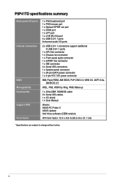
P5P41TD specifications summary Back panel I/O ports Internal connectors BIOS Manageability Accessories Support DVD... Out connector 1 x IDE connector 4 x Serial ATA connectors 1 x System panel connector 1 x 24-pin EATX power connector 1 x 4-pin ATX 12V power connector 8Mb Flash ROM, AMI BIOS, PnP, DMI 2.0, WfM 2.0, ACPI 2.0a, SM BIOS 2.5 WOL, PXE, WOR by Ring...Ultra DMA 100/66/33 cable 2 x Serial ATA cables 1 x I/O shield 1 x User Manual Drivers ASUS PC Probe II ASUS Update Anti-Virus software (OEM version) ATX form factor: 12 in x 8.3 in (30.5 cm x 21.1 cm) * Specifications are subject to change...
P5P41TD specifications summary Back panel I/O ports Internal connectors BIOS Manageability Accessories Support DVD... Out connector 1 x IDE connector 4 x Serial ATA connectors 1 x System panel connector 1 x 24-pin EATX power connector 1 x 4-pin ATX 12V power connector 8Mb Flash ROM, AMI BIOS, PnP, DMI 2.0, WfM 2.0, ACPI 2.0a, SM BIOS 2.5 WOL, PXE, WOR by Ring...Ultra DMA 100/66/33 cable 2 x Serial ATA cables 1 x I/O shield 1 x User Manual Drivers ASUS PC Probe II ASUS Update Anti-Virus software (OEM version) ATX form factor: 12 in x 8.3 in (30.5 cm x 21.1 cm) * Specifications are subject to change...

User Manual
Page 14
... is ON, in sleep mode, or in the bag that came with a standby power LED that lights up to the motherboard, peripherals, or components. P5P41TD SB_PWR P5P41TD Onboard LED ON OFF Standby Power Powered Off 1-4 Chapter 1: Product introduction Onboard LED The motherboard comes with the component. • Before you must shut down... that you install or remove any motherboard component. Failure to do so may cause severe damage to indicate that the system is a reminder that the ATX power supply is switched off mode.
... is ON, in sleep mode, or in the bag that came with a standby power LED that lights up to the motherboard, peripherals, or components. P5P41TD SB_PWR P5P41TD Onboard LED ON OFF Standby Power Powered Off 1-4 Chapter 1: Product introduction Onboard LED The motherboard comes with the component. • Before you must shut down... that you install or remove any motherboard component. Failure to do so may cause severe damage to indicate that the system is a reminder that the ATX power supply is switched off mode.
User Manual
Page 32
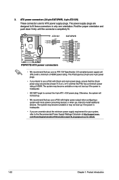
...+3 Volts +3 Volts PIN 1 GND +5 Volts +5 Volts +5 Volts -5 Volts GND GND GND PSON# GND -12 Volts +3 Volts P5P41TD ATX power connectors • We recommend that you intend to install additional devices. The system may become unstable or may not boot up if ...devices or when you use a PSU with a minimum of 400W. com/PowerSupplyCalculator/PSCalculator.aspx?SLanguage=en-us for ATX power supply plugs. The power supply plugs are uncertain about the minimum power supply requirement for your system, refer to...+12 V and that the 20-pin power plug can provide at http://support.asus. 3.
...+3 Volts +3 Volts PIN 1 GND +5 Volts +5 Volts +5 Volts -5 Volts GND GND GND PSON# GND -12 Volts +3 Volts P5P41TD ATX power connectors • We recommend that you intend to install additional devices. The system may become unstable or may not boot up if ...devices or when you use a PSU with a minimum of 400W. com/PowerSupplyCalculator/PSCalculator.aspx?SLanguage=en-us for ATX power supply plugs. The power supply plugs are uncertain about the minimum power supply requirement for your system, refer to...+12 V and that the 20-pin power plug can provide at http://support.asus. 3.

User Manual
Page 35
...or flashes when data is read from or written to this connector. PWR Ground Reset Ground IDE_LED PWRSW RESET * Requires an ATX power supply P5P41TD System panel connector • System power LED (2-pin PLED) This 2-pin connector is for the system power LED. Connect ...-mounted system warning speaker. System panel connector (20-8 pin PANEL) This connector supports several chassis-mounted functions. ASUS P5P41TD 1-25 PLED SPEAKER PLED+ PLED+5V Ground Ground Speaker P5P41TD PANEL PIN 1 IDE_LED+ IDE_LED- 8. The speaker allows you turn on the system power, and blinks when ...
...or flashes when data is read from or written to this connector. PWR Ground Reset Ground IDE_LED PWRSW RESET * Requires an ATX power supply P5P41TD System panel connector • System power LED (2-pin PLED) This 2-pin connector is for the system power LED. Connect ...-mounted system warning speaker. System panel connector (20-8 pin PANEL) This connector supports several chassis-mounted functions. ASUS P5P41TD 1-25 PLED SPEAKER PLED+ PLED+5V Ground Ground Speaker P5P41TD PANEL PIN 1 IDE_LED+ IDE_LED- 8. The speaker allows you turn on the system power, and blinks when ...

User Manual
Page 52
...On By PCI (E) Device [Disabled] When set to [Enabled], this parameter allows you do not wish to display the detected temperatures. This feature requires an ATX power supply that provides at least 1A on the +5VSB lead. Select Ignored if you to enable or disable the CPU Q-Fan function. 2.5.4 APM Configuration...a wake event. When this parameter allows you to enable or disable RTC to [Last State], the system goes into off mode. This feature requires an ATX power supply that provides at least 1A on the +5VSB lead. CPU Q-Fan Control [Enabled] Allows you do not wish to [Power On], the ...
...On By PCI (E) Device [Disabled] When set to [Enabled], this parameter allows you do not wish to display the detected temperatures. This feature requires an ATX power supply that provides at least 1A on the +5VSB lead. Select Ignored if you to enable or disable the CPU Q-Fan function. 2.5.4 APM Configuration...a wake event. When this parameter allows you to enable or disable RTC to [Last State], the system goes into off mode. This feature requires an ATX power supply that provides at least 1A on the +5VSB lead. CPU Q-Fan Control [Enabled] Allows you do not wish to [Power On], the ...

