
P5N-E SLI English Edition User's Manual
Page 12
...voltage: Adjustable CPU voltage at 1MHz increment; - Profile ASUS PC Probe2 ASUS Update 4 MB Flash ROM, Award BIOS, PnP, DMI2.0, SM BIOS 2.3, WfM2.0, ASUS EZ Flash 2, ASUS CrashFree BIOS2 ATX power supply (with 24-pin and 4-pin 12V plugs) ATX 12V 2.0 compliant 1 x Parallel port 1 x ...200MHz to 131MHz at 1MHz increment; - ASUS C.P.R. (CPU Parameter Recall) ASUS Q-Fan2 ASUS Q-Connector ASUS Fanless Design ASUS MyLogo2 ASUS O.C. P5N-E SLI specifications summary USB Overclocking features Special features BIOS features Power Requirement Rear panel Supports up to 1200MHz...
...voltage: Adjustable CPU voltage at 1MHz increment; - Profile ASUS PC Probe2 ASUS Update 4 MB Flash ROM, Award BIOS, PnP, DMI2.0, SM BIOS 2.3, WfM2.0, ASUS EZ Flash 2, ASUS CrashFree BIOS2 ATX power supply (with 24-pin and 4-pin 12V plugs) ATX 12V 2.0 compliant 1 x Parallel port 1 x ...200MHz to 131MHz at 1MHz increment; - ASUS C.P.R. (CPU Parameter Recall) ASUS Q-Fan2 ASUS Q-Connector ASUS Fanless Design ASUS MyLogo2 ASUS O.C. P5N-E SLI specifications summary USB Overclocking features Special features BIOS features Power Requirement Rear panel Supports up to 1200MHz...
P5N-E SLI English Edition User's Manual
Page 13
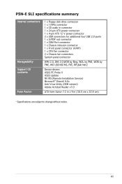
P5N-E SLI specifications summary Internal connectors Manageability Support CD contents Form Factor 1 x Floppy disk drive connector 1 x 1394a connector 1 x CD audio in connector 1 x 24-pin ATX power connector 1 x 4-pin ATX 12 V power connector 2 x USB connectors for additional four USB 2.0 ports 1 x S/PDIF out connector 1 x COM Port connector 1 x Chassis ...USB/KB/MS, PXE, RPL&AI Net2 Device drivers ASUS PC Probe II ASUS Update NV RIS (Remote Installation Service) Microsoft® DirectX 9.0c Anti-Virus Utility (OEM version) Adobe Acrobat Reader v7.0 ATX form factor: 12 in x 9 in (30.5 ...
P5N-E SLI specifications summary Internal connectors Manageability Support CD contents Form Factor 1 x Floppy disk drive connector 1 x 1394a connector 1 x CD audio in connector 1 x 24-pin ATX power connector 1 x 4-pin ATX 12 V power connector 2 x USB connectors for additional four USB 2.0 ports 1 x S/PDIF out connector 1 x COM Port connector 1 x Chassis ...USB/KB/MS, PXE, RPL&AI Net2 Device drivers ASUS PC Probe II ASUS Update NV RIS (Remote Installation Service) Microsoft® DirectX 9.0c Anti-Virus Utility (OEM version) Adobe Acrobat Reader v7.0 ATX form factor: 12 in x 9 in (30.5 ...

P5N-E SLI English Edition User's Manual
Page 40
... and unplug the power cord. 2. Except when clearing the RTC RAM, never remove the cap on pins 2-3 for about 5~10 seconds, then move the cap back to re-enter data. Shut down the key during the boot process and enter BIOS setup to pins 1-2. 4. Re-install the battery. 5. P5N-E SLI R P5N-E SLI Clear RTC RAM ...clear the Real Time Clock (RTC) RAM in CMOS, which include system setup information such as system •words. The onboard button cell battery powers the RAM data in CMOS. Keep the cap on CLRTC jumper default position. To erase the RTC RAM: 1. Move the jumper cap from...
... and unplug the power cord. 2. Except when clearing the RTC RAM, never remove the cap on pins 2-3 for about 5~10 seconds, then move the cap back to re-enter data. Shut down the key during the boot process and enter BIOS setup to pins 1-2. 4. Re-install the battery. 5. P5N-E SLI R P5N-E SLI Clear RTC RAM ...clear the Real Time Clock (RTC) RAM in CMOS, which include system setup information such as system •words. The onboard button cell battery powers the RAM data in CMOS. Keep the cap on CLRTC jumper default position. To erase the RTC RAM: 1. Move the jumper cap from...

P5N-E SLI English Edition User's Manual
Page 41
... (no power to enable or disable the keyboard wake-up the computer when you to CPU, DRAM in slow refresh, power supply in the BIOS. This feature requires an ATX power supply that can supply at least 1A on the +5VSB lead, and a corresponding setting in reduced power mode). KBPWR 3 2 2 1 P5N-E SLI +5V (Default) +5VSB R P5N-E SLI Keyboard Power Setting ASUS P5N-E SLI...
... (no power to enable or disable the keyboard wake-up the computer when you to CPU, DRAM in slow refresh, power supply in the BIOS. This feature requires an ATX power supply that can supply at least 1A on the +5VSB lead, and a corresponding setting in reduced power mode). KBPWR 3 2 2 1 P5N-E SLI +5V (Default) +5VSB R P5N-E SLI Keyboard Power Setting ASUS P5N-E SLI...

P5N-E SLI English Edition User's Manual
Page 45
... RSATA_TXN3 GND RSATA_RXP3 RSATA_RXN3 GND GND RSATA_TXP4 RSATA_TXN4 GND RSATA_RXP4 RSATA_RXN4 GND P5N-E SLI SATA Connectors These connectors support Native Command Queuing (NCQ), Power Management (PM) Implementation Algorithm, Hot Swap and smart setup. 4. Serial ATA connectors (7-pin SATA1 [red], SATA2 [black], SATA3 [red], SATA4 [black]) ..., Third or Fourth SATA Master RAID items in Advanced > Onboard Devices Configuration > NVRAID Configuration of the BIOS. P5N-E SLI R CD (black) Right Audio Channel Ground Ground Left Audio Channel P5N-E SLI Internal Audio Connector ASUS P5N-E SLI 1-31
... RSATA_TXN3 GND RSATA_RXP3 RSATA_RXN3 GND GND RSATA_TXP4 RSATA_TXN4 GND RSATA_RXP4 RSATA_RXN4 GND P5N-E SLI SATA Connectors These connectors support Native Command Queuing (NCQ), Power Management (PM) Implementation Algorithm, Hot Swap and smart setup. 4. Serial ATA connectors (7-pin SATA1 [red], SATA2 [black], SATA3 [red], SATA4 [black]) ..., Third or Fourth SATA Master RAID items in Advanced > Onboard Devices Configuration > NVRAID Configuration of the BIOS. P5N-E SLI R CD (black) Right Audio Channel Ground Ground Left Audio Channel P5N-E SLI Internal Audio Connector ASUS P5N-E SLI 1-31

P5N-E SLI English Edition User's Manual
Page 48
... "Chassis Signal" and "Ground" are for a chassis-mounted intrusion detection sensor or switch. CHASSIS R P5N-E SLI +5VSB_MB Chassis Signal GND P5N-E SLI Intrusion Connector (Default) 10. Chassis intrusion connector (4-1 pin CHASSIS) This connector is for ATX power supply plugs. The chassis intrusion sensor or switch sends a high-level signal to this connector. Find the proper orientation and...
... "Chassis Signal" and "Ground" are for a chassis-mounted intrusion detection sensor or switch. CHASSIS R P5N-E SLI +5VSB_MB Chassis Signal GND P5N-E SLI Intrusion Connector (Default) 10. Chassis intrusion connector (4-1 pin CHASSIS) This connector is for ATX power supply plugs. The chassis intrusion sensor or switch sends a high-level signal to this connector. Find the proper orientation and...

P5N-E SLI English Edition User's Manual
Page 49
... 6600GT x2 2 2 2 2 2 1 0 0 2 1 4 3 > 20A > 17A >= 400W >= 350W 11. ASUS P5N-E SLI 1-35 Connect the S/PDIF Out module cable to this connector, then install the module to a slot opening at the back of 400 W. • Do not forget to connect the 4-pin ATX +12 V power plug; P5N-E SLI R GND SPDIFOUT +5V SPDIF_OUT P5N-E SLI Digital Audio Connector The S/PDIF module is for...
... 6600GT x2 2 2 2 2 2 1 0 0 2 1 4 3 > 20A > 17A >= 400W >= 350W 11. ASUS P5N-E SLI 1-35 Connect the S/PDIF Out module cable to this connector, then install the module to a slot opening at the back of 400 W. • Do not forget to connect the 4-pin ATX +12 V power plug; P5N-E SLI R GND SPDIFOUT +5V SPDIF_OUT P5N-E SLI Digital Audio Connector The S/PDIF module is for...

P5N-E SLI English Edition User's Manual
Page 50
... puts the system in sleep mode. • Hard disk drive activity LED (2-pin IDE_LED) This 2-pin connector is for system reboot without turning off the system power. 1-36 Chapter 1: Product introduction PANEL PLED SPEAKER R IDE_LED RESET PWRSW *Requires an ATX power supply P5N-E SLI System Panel Connector The sytem panel connector is for the chassis-mounted reset...
... puts the system in sleep mode. • Hard disk drive activity LED (2-pin IDE_LED) This 2-pin connector is for system reboot without turning off the system power. 1-36 Chapter 1: Product introduction PANEL PLED SPEAKER R IDE_LED RESET PWRSW *Requires an ATX power supply P5N-E SLI System Panel Connector The sytem panel connector is for the chassis-mounted reset...


