
User Manual
Page 4
... the computer 3-2 3.2.1 Using the OS shut down function 3-2 3.2.2 Using the dual function power switch 3-2 Chapter 4: BIOS setup 4.1 Managing and updating your BIOS 4-1 4.1.1 Creating a bootable floppy disk 4-1 4.1.2 ASUS EZ Flash utility 4-2 4.1.3 AFUDOS utility 4-3 4.1.4 ASUS CrashFree BIOS 2 utility 4-6 4.1.5 ASUS Update utility 4-8 4.2 BIOS setup program 4-11 4.2.1 BIOS menu screen 4-12 4.2.2 Menu bar 4-12 4.2.3 Navigation keys 4-12 4.2.4 Menu items 4-13 4.2.5 Sub-menu...
... the computer 3-2 3.2.1 Using the OS shut down function 3-2 3.2.2 Using the dual function power switch 3-2 Chapter 4: BIOS setup 4.1 Managing and updating your BIOS 4-1 4.1.1 Creating a bootable floppy disk 4-1 4.1.2 ASUS EZ Flash utility 4-2 4.1.3 AFUDOS utility 4-3 4.1.4 ASUS CrashFree BIOS 2 utility 4-6 4.1.5 ASUS Update utility 4-8 4.2 BIOS setup program 4-11 4.2.1 BIOS menu screen 4-12 4.2.2 Menu bar 4-12 4.2.3 Navigation keys 4-12 4.2.4 Menu items 4-13 4.2.5 Sub-menu...
User Manual
Page 8
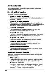
... the ASUS contact information. 2. Refer to the following parts: • Chapter 1: Product introduction This chapter describes the features of the BIOS parameters are not part of shutting down the system. • Chapter 4: BIOS setup Tells how to change system settings through the BIOS Setup ... 3: Powering up This chapter describes the power up sequence, the vocal POST messages, and ways of the standard package. ASUS websites The ASUS website provides updated information on RAID, LAN and VGA driver installation for product and software updates. 1. Detailed descriptions of the...
... the ASUS contact information. 2. Refer to the following parts: • Chapter 1: Product introduction This chapter describes the features of the BIOS parameters are not part of shutting down the system. • Chapter 4: BIOS setup Tells how to change system settings through the BIOS Setup ... 3: Powering up This chapter describes the power up sequence, the vocal POST messages, and ways of the standard package. ASUS websites The ASUS website provides updated information on RAID, LAN and VGA driver installation for product and software updates. 1. Detailed descriptions of the...
User Manual
Page 10
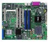
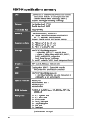
... Southbridge supports: - 8 x USB 2.0 ports (2 on the next page) x P5MT-M specifications summary CPU Chipset Front Side Bus Memory Expansion slots Storage Graphics LAN USB Special features BIOS features Rear panel LGA775 socket for up to 6 additional ports) ASUS Q-Fan ASUS CrashFree BIOS 2 ASUS MyLogo2™ ASUS EZ FLash AMI BIOS, 8 Mb FWH, Green, PnP, DMI2.0a, ACPI 2.0a, SMBIOS...
... Southbridge supports: - 8 x USB 2.0 ports (2 on the next page) x P5MT-M specifications summary CPU Chipset Front Side Bus Memory Expansion slots Storage Graphics LAN USB Special features BIOS features Rear panel LGA775 socket for up to 6 additional ports) ASUS Q-Fan ASUS CrashFree BIOS 2 ASUS MyLogo2™ ASUS EZ FLash AMI BIOS, 8 Mb FWH, Green, PnP, DMI2.0a, ACPI 2.0a, SMBIOS...

User Manual
Page 18
...from the support CD in case when the BIOS codes and data are corrupted. ASUS MyLogo2™ This feature allows you can easily update the system BIOS even before loading the operating system. 1.3.2 Innovative ASUS features ASUS Smart Fan technology The ASUS Smart Fan technology smartly adjusts the fan speeds... according to the system loading to your system with customizable boot logos. See page 4-33 for details. ASUS EZ Flash BIOS With the ASUS EZ Flash, you to personalize and add style to ensure quiet, cool, and efficient operation. See page 4-6 for details. ...
...from the support CD in case when the BIOS codes and data are corrupted. ASUS MyLogo2™ This feature allows you can easily update the system BIOS even before loading the operating system. 1.3.2 Innovative ASUS features ASUS Smart Fan technology The ASUS Smart Fan technology smartly adjusts the fan speeds... according to the system loading to your system with customizable boot logos. See page 4-33 for details. ASUS EZ Flash BIOS With the ASUS EZ Flash, you to personalize and add style to ensure quiet, cool, and efficient operation. See page 4-6 for details. ...

User Manual
Page 24
... RTC RAM (CLRTC1) 2. Gigabit LAN controller setting (3-pin LAN_EN2) 7. LAN 1 (RJ-45) port 8. Gigabit LAN controller setting (3-pin LAN_EN1) 6. USB 2.0 ports 1 and 2 5. DDR2 DIMM sockets 3. BIOS recovery (3-pin RECOVERY1) 9. Parallel port 3. 2.2.4 Layout contents Slots 1. PCI Express/PCI slots Page 2-6 2-13 2-18 Jumpers 1. USB device wake-up (3-pin USBPW12, USBPW34, USBPW56, USBPW78...
... RTC RAM (CLRTC1) 2. Gigabit LAN controller setting (3-pin LAN_EN2) 7. LAN 1 (RJ-45) port 8. Gigabit LAN controller setting (3-pin LAN_EN1) 6. USB 2.0 ports 1 and 2 5. DDR2 DIMM sockets 3. BIOS recovery (3-pin RECOVERY1) 9. Parallel port 3. 2.2.4 Layout contents Slots 1. PCI Express/PCI slots Page 2-6 2-13 2-18 Jumpers 1. USB device wake-up (3-pin USBPW12, USBPW34, USBPW56, USBPW78...
User Manual
Page 28
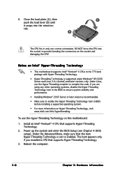
...in the 775-land package with Hyper-Threading Technology. • Hyper-Threading Technology is set to enable the Hyper-Threading Technology item in BIOS before installing a supported operating system. • For more information on this motherboard: 1. Under Linux, use the Hyper-Threading Technology ... is supported under Windows® XP/2003 Server and Linux 2.4.x (kernel) and later versions only. B The CPU fits in the BIOS to ensure system stability and performance. • Installing Windows® 2003 Server or later version is recommended. • Make sure to...
...in the 775-land package with Hyper-Threading Technology. • Hyper-Threading Technology is set to enable the Hyper-Threading Technology item in BIOS before installing a supported operating system. • For more information on this motherboard: 1. Under Linux, use the Hyper-Threading Technology ... is supported under Windows® XP/2003 Server and Linux 2.4.x (kernel) and later versions only. B The CPU fits in the BIOS to ensure system stability and performance. • Installing Windows® 2003 Server or later version is recommended. • Make sure to...
User Manual
Page 36
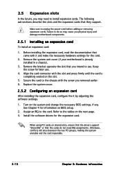
...to the card. Failure to do not need to install expansion cards. Remove the system unit cover (if your motherboard is completely seated on BIOS setup. 2. Remove the bracket opposite the slot that they support. Align the card connector with the slot and press firmly until the card..., making the system unstable and the card inoperable. 2-16 Chapter 2: Hardware information When using PCI cards on the system and change the necessary BIOS settings, if any. Before installing the expansion card, read the documentation that the cards do so may need IRQ assignments. Keep the screw for...
...to the card. Failure to do not need to install expansion cards. Remove the system unit cover (if your motherboard is completely seated on BIOS setup. 2. Remove the bracket opposite the slot that they support. Align the card connector with the slot and press firmly until the card..., making the system unstable and the card inoperable. 2-16 Chapter 2: Hardware information When using PCI cards on the system and change the necessary BIOS settings, if any. Before installing the expansion card, read the documentation that the cards do so may need IRQ assignments. Keep the screw for...
User Manual
Page 39
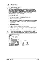
... CMOS RTC RAM data. To erase the RTC RAM: 1. Plug the power cord and turn ON the computer. 6. P5MT-M ® LAN2 P5MT-M Clear RTC RAM CLRTC1 2 1 Normal (Default) 3 2 Clear CMOS ASUS P5MT-M 2-19 Clear RTC RAM (CLRTC1) This jumper allows you to re-enter data. The onboard button cell battery powers... the RAM data in CMOS. Hold down the key during the boot process and enter BIOS setup to clear the Real Time Clock (RTC) ...
... CMOS RTC RAM data. To erase the RTC RAM: 1. Plug the power cord and turn ON the computer. 6. P5MT-M ® LAN2 P5MT-M Clear RTC RAM CLRTC1 2 1 Normal (Default) 3 2 Clear CMOS ASUS P5MT-M 2-19 Clear RTC RAM (CLRTC1) This jumper allows you to re-enter data. The onboard button cell battery powers... the RAM data in CMOS. Hold down the key during the boot process and enter BIOS setup to clear the Real Time Clock (RTC) ...
User Manual
Page 41
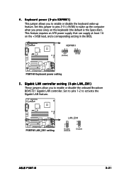
... on the keyboard (the default is the Space Bar). Keyboard power (3-pin KBPWR1) This jumper allows you to wake up feature. P5MT-M ® LAN2 P5MT-M LAN_EN1 setting LAN_EN1 2 1 Enable (Default) 3 2 Disable ASUS P5MT-M 2-21 Set to pins 1-2 to enable or disable the onboard Broadcom BCM5721 Gigabit LAN controller. Set this jumper to pins 2-3 (+5VSB... the Gigabit LAN feature. Gigabit LAN controller setting (3-pin LAN_EN1) These jumpers allow you press a key on the +5VSB lead, and a corresponding setting in the BIOS. ® LAN2 P5MT-M KBPWR1 21 32 +5V (Default) +5VSB...
... on the keyboard (the default is the Space Bar). Keyboard power (3-pin KBPWR1) This jumper allows you to wake up feature. P5MT-M ® LAN2 P5MT-M LAN_EN1 setting LAN_EN1 2 1 Enable (Default) 3 2 Disable ASUS P5MT-M 2-21 Set to pins 1-2 to enable or disable the onboard Broadcom BCM5721 Gigabit LAN controller. Set this jumper to pins 2-3 (+5VSB... the Gigabit LAN feature. Gigabit LAN controller setting (3-pin LAN_EN1) These jumpers allow you press a key on the +5VSB lead, and a corresponding setting in the BIOS. ® LAN2 P5MT-M KBPWR1 21 32 +5V (Default) +5VSB...
User Manual
Page 43
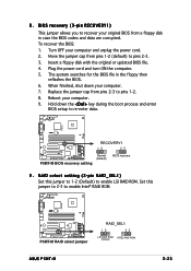
.... 5. Set this jumper to 1-2 (Default) to enable Intel® RAID ROM. Turn OFF your computer. 9. P5MT-M ® LAN2 P5MT-M RAID select jumper RAID_SEL1 12 23 LSI RAID ROM INTEL RAID ROM (Default) ASUS P5MT-M 2-23 To recover the BIOS: 1. RAID select setting (3-pin RAID_SEL1) Set this jumper to 2-3 to enable LSI RAID ROM. 8. Move the...
.... 5. Set this jumper to 1-2 (Default) to enable Intel® RAID ROM. Turn OFF your computer. 9. P5MT-M ® LAN2 P5MT-M RAID select jumper RAID_SEL1 12 23 LSI RAID ROM INTEL RAID ROM (Default) ASUS P5MT-M 2-23 To recover the BIOS: 1. RAID select setting (3-pin RAID_SEL1) Set this jumper to 2-3 to enable LSI RAID ROM. 8. Move the...

User Manual
Page 47
... RAID 10 configuration with the onboard Intel® ICH7R RAID controller. If you intend to create a Serial ATA RAID set using the connectors in the BIOS to these connectors, set to S t a n d a r d I D E mode, connect the primary (boot) hard disk drive to the table below for the recommended SATA hard disk drive connections... the C o n f i g u r e S A T A a s item in S t a n d a r d I D E mode by default. Serial ATA hard disk drive connection Connector SATA1, SATA2 SATA3, SATA4 Setting Master Slave Use Boot disk Data disk ASUS P5MT-M 2-27 4 .
... RAID 10 configuration with the onboard Intel® ICH7R RAID controller. If you intend to create a Serial ATA RAID set using the connectors in the BIOS to these connectors, set to S t a n d a r d I D E mode, connect the primary (boot) hard disk drive to the table below for the recommended SATA hard disk drive connections... the C o n f i g u r e S A T A a s item in S t a n d a r d I D E mode by default. Serial ATA hard disk drive connection Connector SATA1, SATA2 SATA3, SATA4 Setting Master Slave Use Boot disk Data disk ASUS P5MT-M 2-27 4 .

User Manual
Page 54
... POWERLEDMLED+ MLEDNC +5V GND GND SPKROUT ® LAN2 PANEL1 HDLED+ HDLEDNMIBTN# GND POWERBTN# GND NC RESETBTN# GND P5MT-M System panel connector The sytem panel connector is color-coded for easy connection. • System power LED (Green 3-pin POWERLED) This 3-pin connector is for ... OFF. • Reset button (Blue 2-pin RESETBTN) This 2-pin connector is for the chassis-mounted system warning speaker. The speaker allows you turn on the BIOS settings. 15. Connect the HDD Activity LED cable to this connector. Connect the chassis power LED cable to this connector.
... POWERLEDMLED+ MLEDNC +5V GND GND SPKROUT ® LAN2 PANEL1 HDLED+ HDLEDNMIBTN# GND POWERBTN# GND NC RESETBTN# GND P5MT-M System panel connector The sytem panel connector is color-coded for easy connection. • System power LED (Green 3-pin POWERLED) This 3-pin connector is for ... OFF. • Reset button (Blue 2-pin RESETBTN) This 2-pin connector is for the chassis-mounted system warning speaker. The speaker allows you turn on the BIOS settings. 15. Connect the HDD Activity LED cable to this connector. Connect the chassis power LED cable to this connector.

User Manual
Page 57
... For systems with a surge protector. 5. While the tests are off. 3. ASUS P5MT-M 3-1 Turn on self tests or POST. 3.1 Starting up . Monitor b. The system then runs the power-on the devices in Chapter 4. AMI BIOS beep codes Beep Description One beep Two continuous beeps followed by two short beeps ...failure 7. System power 6. Connect the power cord to enter the BIOS Setup. If you do not see BIOS beep codes table below) or additional messages appear on . After making all switches are running, the BIOS beeps (see anything within 30 seconds from the time you press the...
... For systems with a surge protector. 5. While the tests are off. 3. ASUS P5MT-M 3-1 Turn on self tests or POST. 3.1 Starting up . Monitor b. The system then runs the power-on the devices in Chapter 4. AMI BIOS beep codes Beep Description One beep Two continuous beeps followed by two short beeps ...failure 7. System power 6. Connect the power cord to enter the BIOS Setup. If you do not see BIOS beep codes table below) or additional messages appear on . After making all switches are running, the BIOS beeps (see anything within 30 seconds from the time you press the...
User Manual
Page 58
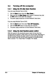
... the S h u t D o w n option button is ON, pressing the power switch for less than four seconds lets the system enter the soft-off mode regardless of the BIOS setting. The power supply should turn off after Windows® shuts down . 3.2.2 Using the dual function power switch While the system is selected, then click...
... the S h u t D o w n option button is ON, pressing the power switch for less than four seconds lets the system enter the soft-off mode regardless of the BIOS setting. The power supply should turn off after Windows® shuts down . 3.2.2 Using the dual function power switch While the system is selected, then click...

User Manual
Page 59
Detailed descriptions of the BIOS parameters are also provided. 4 BIOS setup This chapter tells how to change the system settings through the BIOS Setup menus.
Detailed descriptions of the BIOS parameters are also provided. 4 BIOS setup This chapter tells how to change the system settings through the BIOS Setup menus.

User Manual
Page 60
Chapter summary 4 4.1 Managing and updating your BIOS 4-1 4.2 BIOS setup program 4-11 4.3 Main menu 4-14 4.4 Advanced menu 4-19 4.5 Power menu 4-27 4.6 Boot menu 4-31 4.7 Exit menu 4-35 ASUS P5MT-M
Chapter summary 4 4.1 Managing and updating your BIOS 4-1 4.2 BIOS setup program 4-11 4.3 Main menu 4-14 4.4 Advanced menu 4-19 4.5 Power menu 4-27 4.6 Boot menu 4-31 4.7 Exit menu 4-35 ASUS P5MT-M

User Manual
Page 61
... utilities. DOS environment a. Insert a 1.44 MB floppy disk into the drive. Insert a 1.44 MB floppy disk to create a bootable floppy disk. e. W i n d o w s® X P u s e r s : Select C r e a t e a n M S - ASUS P5MT-M 4-1 Windows® XP environment a. c. Click F i l e from the Windows® desktop, then select M y C o m p u t e r. A S U S A F U D O S (Updates the BIOS in case you to manage and update the motherboard Basic Input/Output System...
... utilities. DOS environment a. Insert a 1.44 MB floppy disk into the drive. Insert a 1.44 MB floppy disk to create a bootable floppy disk. e. W i n d o w s® X P u s e r s : Select C r e a t e a n M S - ASUS P5MT-M 4-1 Windows® XP environment a. c. Click F i l e from the Windows® desktop, then select M y C o m p u t e r. A S U S A F U D O S (Updates the BIOS in case you to manage and update the motherboard Basic Input/Output System...

User Manual
Page 62
...optical drive. Windows® 2000 environment To create a set of booting from a floppy disk and using EZ Flash: 1. Visit the ASUS website (www.asus.com) to download the latest BIOS file for the motherboard and rename the same to continue. 2. Copy the original or the latest motherboard... BIOS file to the bootable floppy disk. 4.1.2 ASUS EZ Flash utility The ASUS EZ Flash feature allows you to update the BIOS without having to go through the long process of boot disks for floppy... 4. ...
...optical drive. Windows® 2000 environment To create a set of booting from a floppy disk and using EZ Flash: 1. Visit the ASUS website (www.asus.com) to download the latest BIOS file for the motherboard and rename the same to continue. 2. Copy the original or the latest motherboard... BIOS file to the bootable floppy disk. 4.1.2 ASUS EZ Flash utility The ASUS EZ Flash feature allows you to update the BIOS without having to go through the long process of boot disks for floppy... 4. ...

User Manual
Page 63
...Make sure that you can use as shown. 1. A:\>afudos /oOLDBIOS1.rom Main filename Extension name ASUS P5MT-M 4-3 Reading file "P5MT-M.ROM". Rebooting. • Do not shut down or reset the system while updating the BIOS to prevent system boot failure! • A "Floppy not found !" This utility also allows ...CD to the bootable floppy disk you to update the BIOS file in DOS mode, then at least 1024 KB free space to P5MT-M.ROM. 4.1.3 AFUDOS utility The AFUDOS utility allows you created earlier. 2. EZFlash starting BIOS update Checking for the extension name. Floppy found in the...
...Make sure that you can use as shown. 1. A:\>afudos /oOLDBIOS1.rom Main filename Extension name ASUS P5MT-M 4-3 Reading file "P5MT-M.ROM". Rebooting. • Do not shut down or reset the system while updating the BIOS to prevent system boot failure! • A "Floppy not found !" This utility also allows ...CD to the bootable floppy disk you to update the BIOS file in DOS mode, then at least 1024 KB free space to P5MT-M.ROM. 4.1.3 AFUDOS utility The AFUDOS utility allows you created earlier. 2. EZFlash starting BIOS update Checking for the extension name. Floppy found in the...

User Manual
Page 64
Press . All rights reserved. Reading flash ..... A:\>afudos /iP5MT-M.ROM /pbnc 4-4 Chapter 4: BIOS setup Version 1.19(ASUS V2.07(03.11.24BB)) Copyright (C) 2002 American Megatrends, Inc. ok A:\> The utility returns to the floppy disk. Visit the ASUS website (www.asus.com) and download the latest BIOS file for the motherboard. 3. A:\>afudos /oOLDBIOS1.rom AMI Firmware Update...
Press . All rights reserved. Reading flash ..... A:\>afudos /iP5MT-M.ROM /pbnc 4-4 Chapter 4: BIOS setup Version 1.19(ASUS V2.07(03.11.24BB)) Copyright (C) 2002 American Megatrends, Inc. ok A:\> The utility returns to the floppy disk. Visit the ASUS website (www.asus.com) and download the latest BIOS file for the motherboard. 3. A:\>afudos /oOLDBIOS1.rom AMI Firmware Update...


