
User Guide
Page 3
Contents Notices vi Safety information vii About this guide viii P5MT Series specifications summary x Chapter 1: Product introduction 1.1 Welcome 1-1 1.2 Package contents 1-1 1.3 Special features 1-2 1.3.1 Product highlights 1-2 1.3.2 Innovative ASUS features 1-4 Chapter 2: Hardware information 2.1 Before you proceed 2-1 2.2 Motherboard overview 2-2 2.2.1 Placement direction 2-2 2.2.2 Screw holes 2-2 2.2.3 Motherboard layouts 2-3 2.2.4 Layout contents 2-5 2.3 Central Processing Unit (CPU 2-7 2.3.1 Installing the CPU 2-7 2.3.2 Installing ...
Contents Notices vi Safety information vii About this guide viii P5MT Series specifications summary x Chapter 1: Product introduction 1.1 Welcome 1-1 1.2 Package contents 1-1 1.3 Special features 1-2 1.3.1 Product highlights 1-2 1.3.2 Innovative ASUS features 1-4 Chapter 2: Hardware information 2.1 Before you proceed 2-1 2.2 Motherboard overview 2-2 2.2.1 Placement direction 2-2 2.2.2 Screw holes 2-2 2.2.3 Motherboard layouts 2-3 2.2.4 Layout contents 2-5 2.3 Central Processing Unit (CPU 2-7 2.3.1 Installing the CPU 2-7 2.3.2 Installing ...

User Guide
Page 11
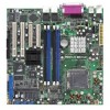
... summary CPU Chipset Front Side Bus Memory Expansion slots* Storage P5MT P5MT/SCSI LGA775 socket for ASUS® Server Management Board Intel® ICH7R Southbridge supports: - 2 x Ultra ATA 100/66/33 hard disk drives - 4 x SATA-300 hard disk drives with RAID functionality ... 4 x 240-pin DIMM sockets support unbuffered ECC/non-ECC DDR2-533/667 memory modules Supports 256 MB up to the PCI Express x16 slot may run only at x1 speed (Intel spec). • For P5MT model: When one PCI-X slot is occupied, the PCI-X frequency is 100 MHz. When two PCI-X slots...
... summary CPU Chipset Front Side Bus Memory Expansion slots* Storage P5MT P5MT/SCSI LGA775 socket for ASUS® Server Management Board Intel® ICH7R Southbridge supports: - 2 x Ultra ATA 100/66/33 hard disk drives - 4 x SATA-300 hard disk drives with RAID functionality ... 4 x 240-pin DIMM sockets support unbuffered ECC/non-ECC DDR2-533/667 memory modules Supports 256 MB up to the PCI Express x16 slot may run only at x1 speed (Intel spec). • For P5MT model: When one PCI-X slot is occupied, the PCI-X frequency is 100 MHz. When two PCI-X slots...

User Guide
Page 16
...to 10.7 GB/s. This high speed interface is software compatible with the Intel® EM64T (Extended Memory 64 Technology). The MCH provides the processor, dual-channel DDR2-533/667 memory, and PCI Express interfaces. See the Appendix for details. 1-2 Chapter 1: Product introduction PCI Express...® 4 processor with a 775-pin surface mount Land Grid Array (LGA) socket designed for details. The dual-channel memory architecture doubles the bandwidth of system memory for PCI 2.3, USB 2.0, and SATA among others. See page 4-21 and the Appendix for the Intel® Pentium®...
...to 10.7 GB/s. This high speed interface is software compatible with the Intel® EM64T (Extended Memory 64 Technology). The MCH provides the processor, dual-channel DDR2-533/667 memory, and PCI Express interfaces. See the Appendix for details. 1-2 Chapter 1: Product introduction PCI Express...® 4 processor with a 775-pin surface mount Land Grid Array (LGA) socket designed for details. The dual-channel memory architecture doubles the bandwidth of system memory for PCI 2.3, USB 2.0, and SATA among others. See page 4-21 and the Appendix for the Intel® Pentium®...
User Guide
Page 20
Chapter summary 2 2.1 Before you proceed 2-1 2.2 Motherboard overview 2-2 2.3 Central Processing Unit (CPU 2-7 2.4 System memory 2-13 2.5 Expansion slots 2-15 2.6 Jumpers 2-18 2.7 Connectors 2-23 ASUS P5MT Series
Chapter summary 2 2.1 Before you proceed 2-1 2.2 Motherboard overview 2-2 2.3 Central Processing Unit (CPU 2-7 2.4 System memory 2-13 2.5 Expansion slots 2-15 2.6 Jumpers 2-18 2.7 Connectors 2-23 ASUS P5MT Series
User Guide
Page 29
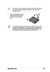
The CPU fits in only one correct orientation. Close the load plate (A), then A push the load lever (B) until it snaps into the socket to the Appendix for more information on the socket and damaging the CPU! 6. ASUS P5MT Series 2-9 Refer to prevent bending the connectors on these CPU features. DO NOT force the CPU into the retention tab. B The motherboard supports Intel® Pentium® 4 LGA775 processors with the Intel® Enhanced Memory 64 Technology (EM64T), Enhanced Intel SpeedStep® Technology (EIST), and Hyper-Threading Technology.
The CPU fits in only one correct orientation. Close the load plate (A), then A push the load lever (B) until it snaps into the socket to the Appendix for more information on the socket and damaging the CPU! 6. ASUS P5MT Series 2-9 Refer to prevent bending the connectors on these CPU features. DO NOT force the CPU into the retention tab. B The motherboard supports Intel® Pentium® 4 LGA775 processors with the Intel® Enhanced Memory 64 Technology (EM64T), Enhanced Intel SpeedStep® Technology (EIST), and Hyper-Threading Technology.
User Guide
Page 33
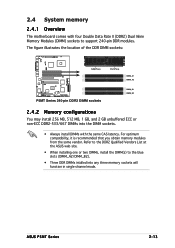
2.4 System memory 2.4.1 Overview The motherboard comes with the same CAS latency. ASUS P5MT Series 2-13 Refer to the DDR2 Qualified Vendors List at the ASUS web site. • When installing one or two DIMMs, install the DIMM(s) to the blue slots (DIMM_A2/DIMM_B2). • Three DDR DIMMs ... same vendor. The figure illustrates the location of the DDR DIMM sockets: ® 128 Pins 112 Pins LAN2 DIMM_A1 DIMM_A2 P5MT Series 240-pin DDR2 DIMM sockets DIMM_B1 DIMM_B2 2.4.2 Memory configurations You may install 256 MB, 512 MB, 1 GB, and 2 GB unbuffered ECC or non-ECC DDR2-533/667...
2.4 System memory 2.4.1 Overview The motherboard comes with the same CAS latency. ASUS P5MT Series 2-13 Refer to the DDR2 Qualified Vendors List at the ASUS web site. • When installing one or two DIMMs, install the DIMM(s) to the blue slots (DIMM_A2/DIMM_B2). • Three DDR DIMMs ... same vendor. The figure illustrates the location of the DDR DIMM sockets: ® 128 Pins 112 Pins LAN2 DIMM_A1 DIMM_A2 P5MT Series 240-pin DDR2 DIMM sockets DIMM_B1 DIMM_B2 2.4.2 Memory configurations You may install 256 MB, 512 MB, 1 GB, and 2 GB unbuffered ECC or non-ECC DDR2-533/667...

User Guide
Page 38
Removing the cap will cause system boot failure! ® LAN2 CLRTC1 12 23 Normal (Default) P5MT Series Clear RTC RAM Clear CMOS 2-18 Chapter 2: Hardware information Re-install the battery. 5. Move the jumper cap from pins 1-2 (default) to re-enter data. 2.6 ... the computer. 6. Hold down the key during the boot process and enter BIOS setup to pins 2-3. Remove the onboard battery. 3. You can clear the CMOS memory of date, time, and system setup parameters by erasing the CMOS RTC RAM data. The onboard button cell battery powers the RAM data in certain...
Removing the cap will cause system boot failure! ® LAN2 CLRTC1 12 23 Normal (Default) P5MT Series Clear RTC RAM Clear CMOS 2-18 Chapter 2: Hardware information Re-install the battery. 5. Move the jumper cap from pins 1-2 (default) to re-enter data. 2.6 ... the computer. 6. Hold down the key during the boot process and enter BIOS setup to pins 2-3. Remove the onboard battery. 3. You can clear the CMOS memory of date, time, and system setup parameters by erasing the CMOS RTC RAM data. The onboard button cell battery powers the RAM data in certain...

User Guide
Page 75
... UTILITY Processor Type Speed Count : Genuine Intel(R) CPU 3.20GHz : 3200 MHz : 1 System Memory Total : 1024MB Select Screen Select Item +- Change Option F1 General Help F10 Save and Exit ESC Exit v02.58 (C)Copyright 1985-2004, American Megatrends, Inc. ASUS P5MT Series 4-17 The BIOS automatically detects the items in this menu. AMI BIOS...
... UTILITY Processor Type Speed Count : Genuine Intel(R) CPU 3.20GHz : 3200 MHz : 1 System Memory Total : 1024MB Select Screen Select Item +- Change Option F1 General Help F10 Save and Exit ESC Exit v02.58 (C)Copyright 1985-2004, American Megatrends, Inc. ASUS P5MT Series 4-17 The BIOS automatically detects the items in this menu. AMI BIOS...

User Guide
Page 77
...terminal type. Configuration options: [Disabled] [Enabled] Serial Port Mode [115200 8,n,1] Sets the Serial port mode. Configuration options: [ANSI] [VT100] [VT-UTF8] ASUS P5MT Series 4-19 Configuration options: [Disabled] [Enabled] When the R e m o t e A c c e s s item is set to select the ... [Disabled] Serial port number Base Address, IRQ Serial Port Mode Flow Control Redirection After BIOS POST Terminal Type VT-UTFB Combo Key Support Sredir Memory Display Delay [COM1] [3F8h, 4] [115200 8,n,1] [None] [Always] [ANSI] [Disabled] [No Delay] Select Remote Access type. Configuration...
...terminal type. Configuration options: [Disabled] [Enabled] Serial Port Mode [115200 8,n,1] Sets the Serial port mode. Configuration options: [ANSI] [VT100] [VT-UTF8] ASUS P5MT Series 4-19 Configuration options: [Disabled] [Enabled] When the R e m o t e A c c e s s item is set to select the ... [Disabled] Serial port number Base Address, IRQ Serial Port Mode Flow Control Redirection After BIOS POST Terminal Type VT-UTFB Combo Key Support Sredir Memory Display Delay [COM1] [3F8h, 4] [115200 8,n,1] [None] [Always] [ANSI] [Disabled] [No Delay] Select Remote Access type. Configuration...

User Guide
Page 78
... values. Change Option F1 General Help F10 Save and Exit ESC Exit v02.58 (C)Copyright 1985-2004, American Megatrends, Inc. Configuration options: [Disabled] [Enabled] Sredir Memory Display Delay [No Delay] Allows you installed an unlocked CPU. Max CPUID Value Limit [Disabled] Setting this item to [Enabled] allows legacy operating systems to...
... values. Change Option F1 General Help F10 Save and Exit ESC Exit v02.58 (C)Copyright 1985-2004, American Megatrends, Inc. Configuration options: [Disabled] [Enabled] Sredir Memory Display Delay [No Delay] Allows you installed an unlocked CPU. Max CPUID Value Limit [Disabled] Setting this item to [Enabled] allows legacy operating systems to...
User Guide
Page 81
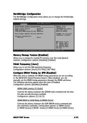
... by SPD [Enabled] Boots Graphic Adapter Priority [PEG/PCI] PEG Port Configuration PEG Port [Auto] ENABLE: Allow remapping of memory. Configuration options: [2 DRAM Clocks] [3 DRAM Clocks] [4 DRAM Clocks] [5 DRAM Clocks] [6 DRAM Clocks] ASUS P5MT Series 4-23 Change Option F1 General Help F10 Save and Exit ESC Exit v02.58 (C)Copyright 1985-2004, American...
... by SPD [Enabled] Boots Graphic Adapter Priority [PEG/PCI] PEG Port Configuration PEG Port [Auto] ENABLE: Allow remapping of memory. Configuration options: [2 DRAM Clocks] [3 DRAM Clocks] [4 DRAM Clocks] [5 DRAM Clocks] [6 DRAM Clocks] ASUS P5MT Series 4-23 Change Option F1 General Help F10 Save and Exit ESC Exit v02.58 (C)Copyright 1985-2004, American...

User Guide
Page 85
The menu includes setting the IRQ and DMA channel resources for either PCI/PnP or legacy ISA devices, and setting the memory size block for PCI/PnP devices. Advanced Advanced PCI/PnP Settings BIOS SETUP UTILITY Plug and Play OS PCI Latency Timer Allocate IRQ to PCI ... requested. Change Option F1 General Help F10 Save and Exit ESC Exit v02.58 (C)Copyright 1985-2004, American Megatrends, Inc. Configuration options: [PCI Device] [Reserved] ASUS P5MT Series 4-27
The menu includes setting the IRQ and DMA channel resources for either PCI/PnP or legacy ISA devices, and setting the memory size block for PCI/PnP devices. Advanced Advanced PCI/PnP Settings BIOS SETUP UTILITY Plug and Play OS PCI Latency Timer Allocate IRQ to PCI ... requested. Change Option F1 General Help F10 Save and Exit ESC Exit v02.58 (C)Copyright 1985-2004, American Megatrends, Inc. Configuration options: [PCI Device] [Reserved] ASUS P5MT Series 4-27

User Guide
Page 137
... FDISK command. If not, the old partitioning data will affect drive letter assignment(s) if more than one device is moved between adapters from different vendors. ASUS P5MT Series 5-37 Changing this item may be reused, thus nullifying the previous operation. CHS Mapping allows either S C S I P l u g a n d... l t e r n a t e C H S M a p p i n g. SCSI Bus Scan Order Indicates the order in which to clear memory. CHS Mapping Defines how the Cylinder Head Sector values are mapped into a disk without pre-existing partition information. Changing this item will be required if...
... FDISK command. If not, the old partitioning data will affect drive letter assignment(s) if more than one device is moved between adapters from different vendors. ASUS P5MT Series 5-37 Changing this item may be reused, thus nullifying the previous operation. CHS Mapping allows either S C S I P l u g a n d... l t e r n a t e C H S M a p p i n g. SCSI Bus Scan Order Indicates the order in which to clear memory. CHS Mapping Defines how the Cylinder Head Sector values are mapped into a disk without pre-existing partition information. Changing this item will be required if...


