User Guide
Page 15
... package with the list below. 1.2 Package contents Check your retailer. Before you for the following items. Motherboard ASUS P5MT or P5MT/SCSI motherboard Cables Accessories Application CDs Documentation 4 x Serial ATA signal cables 2 x Serial ATA power cables 1 x SCSI Ultra320 cable... IDE cable 3-in the long line of the above items is damaged or missing, contact your motherboard package for buying an ASUS® P5MT Series motherboard! ASUS P5MT Series 1-1 1.1 Welcome! Thank you start installing the motherboard, and hardware devices on it another standout in -1 Floppy/Ultra ...
... package with the list below. 1.2 Package contents Check your retailer. Before you for the following items. Motherboard ASUS P5MT or P5MT/SCSI motherboard Cables Accessories Application CDs Documentation 4 x Serial ATA signal cables 2 x Serial ATA power cables 1 x SCSI Ultra320 cable... IDE cable 3-in the long line of the above items is damaged or missing, contact your motherboard package for buying an ASUS® P5MT Series motherboard! ASUS P5MT Series 1-1 1.1 Welcome! Thank you start installing the motherboard, and hardware devices on it another standout in -1 Floppy/Ultra ...

User Guide
Page 17
...Serial ATA II technology through the Serial ATA interfaces controlled by the Intel® ICH7R. See page 2-25 and Chapter 5 for details. ASUS P5MT Series 1-3 USB 2.0 is onboard to support one 68-pin Ultra320 SCSI connector, that supports an optional Zero-Channel RAID card. See ...controllers use the PCI Express interface and could achieve network throughput close to a fast 480 Mbps on USB 2.0. Ultra320 SCSI feature (P5MT/SCSI model only) The LSI53C1020A PCI-X SCSI controller is backward compatible with dual Gigabit LAN controllers and ports to provide a total solution...
...Serial ATA II technology through the Serial ATA interfaces controlled by the Intel® ICH7R. See page 2-25 and Chapter 5 for details. ASUS P5MT Series 1-3 USB 2.0 is onboard to support one 68-pin Ultra320 SCSI connector, that supports an optional Zero-Channel RAID card. See ...controllers use the PCI Express interface and could achieve network throughput close to a fast 480 Mbps on USB 2.0. Ultra320 SCSI feature (P5MT/SCSI model only) The LSI53C1020A PCI-X SCSI controller is backward compatible with dual Gigabit LAN controllers and ports to provide a total solution...
User Guide
Page 20
Chapter summary 2 2.1 Before you proceed 2-1 2.2 Motherboard overview 2-2 2.3 Central Processing Unit (CPU 2-7 2.4 System memory 2-13 2.5 Expansion slots 2-15 2.6 Jumpers 2-18 2.7 Connectors 2-23 ASUS P5MT Series
Chapter summary 2 2.1 Before you proceed 2-1 2.2 Motherboard overview 2-2 2.3 Central Processing Unit (CPU 2-7 2.4 System memory 2-13 2.5 Expansion slots 2-15 2.6 Jumpers 2-18 2.7 Connectors 2-23 ASUS P5MT Series
User Guide
Page 21
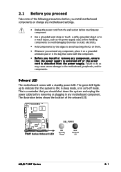
2.1 Before you proceed Take note of the onboard LED. ® LAN2 SB_PWR1 P5MT Series Onboard LED ON Standby Power OFF Powered Off ASUS P5MT Series 2-1 This is a reminder that the system is switched off mode. The green LED lights up to indicate that you should shut down the system ...
2.1 Before you proceed Take note of the onboard LED. ® LAN2 SB_PWR1 P5MT Series Onboard LED ON Standby Power OFF Powered Off ASUS P5MT Series 2-1 This is a reminder that the system is switched off mode. The green LED lights up to indicate that you should shut down the system ...

User Guide
Page 23
... PS/2KBMS KBPWR1 T: Mouse PSUSMB1 B: Keyboard USBPW12 USB12 REAR_FAN1 25cm (9.8in) ATXPWR1 ATX12V1 CPU_FAN1 COM1 REAR_FAN2 CPU_FAN2 FM_CPU2 Intel E7230 FM_CPU1 LGA775 PARALLEL PORT ® P5MT LAN_EN1 LAN_EN2 VGA1 LAN1 LAN2 Broadcom BCM5721 Broadcom BCM5721 DDR2 DIMM_A1 (64 bit,240-pin module) DDR2 DIMM_A2 (64 bit,240-pin module) DDR2 DIMM_B1... PCI4 BPSMB1 TRPWR1 AUX_PANEL1 BMCCONN1 HDLED1 CLRTC1 CR2032 3V Lithium Cell BUZZ1 CMOS Power USBPW34 USB34 PANEL1 Intel 6702 PXH FLOPPY1 PRI_IDE1 30.5cm (12in) ASUS P5MT Series 2-3
... PS/2KBMS KBPWR1 T: Mouse PSUSMB1 B: Keyboard USBPW12 USB12 REAR_FAN1 25cm (9.8in) ATXPWR1 ATX12V1 CPU_FAN1 COM1 REAR_FAN2 CPU_FAN2 FM_CPU2 Intel E7230 FM_CPU1 LGA775 PARALLEL PORT ® P5MT LAN_EN1 LAN_EN2 VGA1 LAN1 LAN2 Broadcom BCM5721 Broadcom BCM5721 DDR2 DIMM_A1 (64 bit,240-pin module) DDR2 DIMM_A2 (64 bit,240-pin module) DDR2 DIMM_B1... PCI4 BPSMB1 TRPWR1 AUX_PANEL1 BMCCONN1 HDLED1 CLRTC1 CR2032 3V Lithium Cell BUZZ1 CMOS Power USBPW34 USB34 PANEL1 Intel 6702 PXH FLOPPY1 PRI_IDE1 30.5cm (12in) ASUS P5MT Series 2-3
User Guide
Page 25
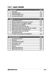
... 2-20 2-20 Page 2-18 2-19 2-19 2-20 2-21 2-21 2-22 2-22 Page 2-23 2-23 2-23 2-23 2-23 2-23 2-23 2-23 ASUS P5MT Series 2-5 VGA controller setting (3-pin VGA_EN1) 6. SCSI controller setting (3-pin SCSI_EN1) (P5MT/SCSI model only) 9. Parallel port 3. VGA port 7. Keyboard power (3-pin KBPWR1) 5. Serial (COM1) port 6. Gigabit LAN1 (RJ-45) port...
... 2-20 2-20 Page 2-18 2-19 2-19 2-20 2-21 2-21 2-22 2-22 Page 2-23 2-23 2-23 2-23 2-23 2-23 2-23 2-23 ASUS P5MT Series 2-5 VGA controller setting (3-pin VGA_EN1) 6. SCSI controller setting (3-pin SCSI_EN1) (P5MT/SCSI model only) 9. Parallel port 3. VGA port 7. Keyboard power (3-pin KBPWR1) 5. Serial (COM1) port 6. Gigabit LAN1 (RJ-45) port...

User Guide
Page 27
...; Upon purchase of the motherboard, make sure that the PnP cap is on the motherboard. ASUS will shoulder the cost of the PnP cap. 2.3.1 Installing the CPU To install a CPU: 1. Contact your left. ® ASUS P5MT Series 2-7 LAN2 P5MT Series CPU Socket 775 Before installing the CPU, make sure that the cam box is...
...; Upon purchase of the motherboard, make sure that the PnP cap is on the motherboard. ASUS will shoulder the cost of the PnP cap. 2.3.1 Installing the CPU To install a CPU: 1. Contact your left. ® ASUS P5MT Series 2-7 LAN2 P5MT Series CPU Socket 775 Before installing the CPU, make sure that the cam box is...
User Guide
Page 29
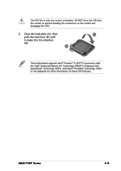
Close the load plate (A), then A push the load lever (B) until it snaps into the socket to the Appendix for more information on the socket and damaging the CPU! 6. B The motherboard supports Intel® Pentium® 4 LGA775 processors with the Intel® Enhanced Memory 64 Technology (EM64T), Enhanced Intel SpeedStep® Technology (EIST), and Hyper-Threading Technology. Refer to prevent bending the connectors on these CPU features. ASUS P5MT Series 2-9 The CPU fits in only one correct orientation. DO NOT force the CPU into the retention tab.
Close the load plate (A), then A push the load lever (B) until it snaps into the socket to the Appendix for more information on the socket and damaging the CPU! 6. B The motherboard supports Intel® Pentium® 4 LGA775 processors with the Intel® Enhanced Memory 64 Technology (EM64T), Enhanced Intel SpeedStep® Technology (EIST), and Hyper-Threading Technology. Refer to prevent bending the connectors on these CPU features. ASUS P5MT Series 2-9 The CPU fits in only one correct orientation. DO NOT force the CPU into the retention tab.
User Guide
Page 31
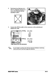
Connect the CPU fan cable to secure the heatsink and fan B assembly in place. Push down two fasteners at a time in a diagonal sequence to the connector on the motherboard labeled CPU_FAN. A A A B B B A 3. ASUS P5MT Series 2-11 CPU_FAN1 CPU_FAN1 ® GND FANPWR2 FANOUT4 LAN2 CPU_FAN2 CPU_FAN2 FANOUT4 FANPWR2 GND P5MT Series CPU fan connectors Do not forget to plug this connector. Hardware monitoring errors can occur if you fail to connect the CPU fan connector! 2.
Connect the CPU fan cable to secure the heatsink and fan B assembly in place. Push down two fasteners at a time in a diagonal sequence to the connector on the motherboard labeled CPU_FAN. A A A B B B A 3. ASUS P5MT Series 2-11 CPU_FAN1 CPU_FAN1 ® GND FANPWR2 FANOUT4 LAN2 CPU_FAN2 CPU_FAN2 FANOUT4 FANPWR2 GND P5MT Series CPU fan connectors Do not forget to plug this connector. Hardware monitoring errors can occur if you fail to connect the CPU fan connector! 2.
User Guide
Page 33
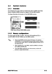
2.4 System memory 2.4.1 Overview The motherboard comes with the same CAS latency. Refer to the DDR2 Qualified Vendors List at the ASUS web site. • When installing one or two DIMMs, install the DIMM(s) to the blue slots (DIMM_A2/DIMM_B2). • Three DDR DIMMs intalled into ... obtain memory modules from the same vendor. The figure illustrates the location of the DDR DIMM sockets: ® 128 Pins 112 Pins LAN2 DIMM_A1 DIMM_A2 P5MT Series 240-pin DDR2 DIMM sockets DIMM_B1 DIMM_B2 2.4.2 Memory configurations You may install 256 MB, 512 MB, 1 GB, and 2 GB unbuffered ECC or non-...
2.4 System memory 2.4.1 Overview The motherboard comes with the same CAS latency. Refer to the DDR2 Qualified Vendors List at the ASUS web site. • When installing one or two DIMMs, install the DIMM(s) to the blue slots (DIMM_A2/DIMM_B2). • Three DDR DIMMs intalled into ... obtain memory modules from the same vendor. The figure illustrates the location of the DDR DIMM sockets: ® 128 Pins 112 Pins LAN2 DIMM_A1 DIMM_A2 P5MT Series 240-pin DDR2 DIMM sockets DIMM_B1 DIMM_B2 2.4.2 Memory configurations You may install 256 MB, 512 MB, 1 GB, and 2 GB unbuffered ECC or non-...
User Guide
Page 35
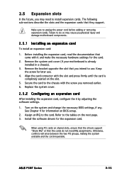
... change the necessary BIOS settings, if any. Failure to the chassis with it by adjusting the software settings. 1. Install the software drivers for later use . ASUS P5MT Series 2-15 Secure the card to do not need to install expansion cards. Assign an IRQ to unplug the power cord before adding or removing...
... change the necessary BIOS settings, if any. Failure to the chassis with it by adjusting the software settings. 1. Install the software drivers for later use . ASUS P5MT Series 2-15 Secure the card to do not need to install expansion cards. Assign an IRQ to unplug the power cord before adding or removing...
User Guide
Page 37
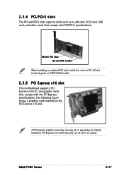
...PCI Express I /O, and graphic cards that comply with the PCI Express specifications. A PCI Express graphics card may only run only at x8 or x4 speed. ASUS P5MT Series 2-17 2.5.4 PCI/PCI-X slots The PCI and PCI-X slots support cards such as a LAN card, SCSI card, USB card, and other cards that ...ZCR card, install the card on PCI_X2 slot (colored green on the PCI Express x16 slot. The following figure shows a graphics card installed on P5MT/SCSI model). 2.5.5 PCI Express x16 slot This motherboard supports PCI Express x16 I /O cards may run at x1 speed due to chipset limitation.
...PCI Express I /O, and graphic cards that comply with the PCI Express specifications. A PCI Express graphics card may only run only at x8 or x4 speed. ASUS P5MT Series 2-17 2.5.4 PCI/PCI-X slots The PCI and PCI-X slots support cards such as a LAN card, SCSI card, USB card, and other cards that ...ZCR card, install the card on PCI_X2 slot (colored green on the PCI Express x16 slot. The following figure shows a graphics card installed on P5MT/SCSI model). 2.5.5 PCI Express x16 slot This motherboard supports PCI Express x16 I /O cards may run at x1 speed due to chipset limitation.

User Guide
Page 39
... fan 4-pin fan (Default) FM_CPU2 1 2 3-pin fan 2 3 4-pin fan (Default) ® ® 3 . USBPW12 12 23 +5V +5VSB LAN2 (Default) USBPW34 12 23 +5V (Default) P5MT Series USB device wake-up +5VSB • The USB device wake-up from S4 sleep mode (no power to wake up the system from S1... sleep mode (CPU stopped, DRAM refreshed, system running in sleep mode. ASUS P5MT Series 2-19 otherwise, the system would not power up the computer from S4 sleep mode. • The total current consumed must NOT exceed the ...
... fan 4-pin fan (Default) FM_CPU2 1 2 3-pin fan 2 3 4-pin fan (Default) ® ® 3 . USBPW12 12 23 +5V +5VSB LAN2 (Default) USBPW34 12 23 +5V (Default) P5MT Series USB device wake-up +5VSB • The USB device wake-up from S4 sleep mode (no power to wake up the system from S1... sleep mode (CPU stopped, DRAM refreshed, system running in sleep mode. ASUS P5MT Series 2-19 otherwise, the system would not power up the computer from S4 sleep mode. • The total current consumed must NOT exceed the ...
User Guide
Page 41
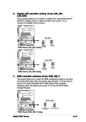
... 2-3 to enable or disable the onboard Broadcom® BCM5721 Gigabit LAN1 or LAN2 controller. 6 . LAN2 RAID_SEL1 1 2 LSI RAID ROM (Default) 2 3 INTEL RAID ROM P5MT Series RAID_SEL1 setting ASUS P5MT Series 2-21 RAID controller selection (3-pin RAID_SEL1) This jumper allows you to select the RAID configuration utility to use when you want to activate...
... 2-3 to enable or disable the onboard Broadcom® BCM5721 Gigabit LAN1 or LAN2 controller. 6 . LAN2 RAID_SEL1 1 2 LSI RAID ROM (Default) 2 3 INTEL RAID ROM P5MT Series RAID_SEL1 setting ASUS P5MT Series 2-21 RAID controller selection (3-pin RAID_SEL1) This jumper allows you to select the RAID configuration utility to use when you want to activate...
User Guide
Page 43
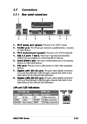
... BLINKING No link Linked Data activity OFF ORANGE GREEN 10 Mbps connection 100 Mbps connection 1000 Mbps connection ACT/LINK SPEED LED LED LAN port ASUS P5MT Series 2-23 S e r i a l ( C O M 1 ) p o r t. This port is for a VGA monitor or other devices. 3 . G i g a b i t L A N 1 ( R J - 4 5 ) p o r t . Refer to the table below for connecting USB 2.0 devices. 5 . Refer to the table below...
... BLINKING No link Linked Data activity OFF ORANGE GREEN 10 Mbps connection 100 Mbps connection 1000 Mbps connection ACT/LINK SPEED LED LED LAN port ASUS P5MT Series 2-23 S e r i a l ( C O M 1 ) p o r t. This port is for a VGA monitor or other devices. 3 . G i g a b i t L A N 1 ( R J - 4 5 ) p o r t . Refer to the table below for connecting USB 2.0 devices. 5 . Refer to the table below...
User Guide
Page 45
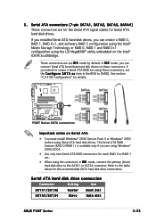
... recommended SATA hard disk drive connections. Serial ATA hard disk drive connection Connector Setting Use SATA1/SATA2 SATA3/SATA4 Master Slave Boot disk Data disk ASUS P5MT Series 2-25 SATA4 SATA2 ® GND GND RSATA_TXP4 RSATA_TXP2 RSATA_TXN4 RSATA_TXN2 GND GND RSATA_RXP4 RSATA_RXP2 LAN2 RSATA_RXN4 RSATA_RXN2 GND GND SATA3 SATA1 GND RSATA_TXP3 RSATA_TXN3...
... recommended SATA hard disk drive connections. Serial ATA hard disk drive connection Connector Setting Use SATA1/SATA2 SATA3/SATA4 Master Slave Boot disk Data disk ASUS P5MT Series 2-25 SATA4 SATA2 ® GND GND RSATA_TXP4 RSATA_TXP2 RSATA_TXN4 RSATA_TXN2 GND GND RSATA_RXP4 RSATA_RXP2 LAN2 RSATA_RXN4 RSATA_RXN2 GND GND SATA3 SATA1 GND RSATA_TXP3 RSATA_TXN3...
User Guide
Page 47
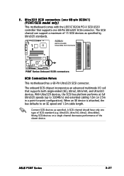
Connect SCSI devices as specified by Ultra320 standards. ASUS P5MT Series 2-27 6 . With Ultra320 devices, the SCSI bus ...device. The onboard SCSI chipset incorporates an advanced multimode I/O cell that supports one 68-pin SCSIA1) (P5MT/SCSI model only) This motherboard comes with the LSI53C1020A PCI-X SCSI U320 controller that supports both single...and Ultra320 devices. SCSIA1 68-Pin Ultra320/ 1 35 Ultra2-Wide SCSI Connector ® LAN2 34 68 P5MT Series Onboard SCSI connectors SCSI Connection Notes This motherboard has a 68-Pin Ultra320 SCSI connector. Mixing SCSI devices...
Connect SCSI devices as specified by Ultra320 standards. ASUS P5MT Series 2-27 6 . With Ultra320 devices, the SCSI bus ...device. The onboard SCSI chipset incorporates an advanced multimode I/O cell that supports one 68-pin SCSIA1) (P5MT/SCSI model only) This motherboard comes with the LSI53C1020A PCI-X SCSI U320 controller that supports both single...and Ultra320 devices. SCSIA1 68-Pin Ultra320/ 1 35 Ultra2-Wide SCSI Connector ® LAN2 34 68 P5MT Series Onboard SCSI connectors SCSI Connection Notes This motherboard has a 68-Pin Ultra320 SCSI connector. Mixing SCSI devices...
User Guide
Page 49
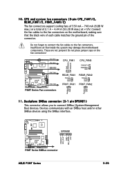
...host and/or other SMBus devices using the SMBus interface. ® FANOUT I2C_CLK GND I2C_DATA +5V BPSMB1 LAN2 1 P5MT Series SMBus connector ASUS P5MT Series 2-29 Do not place jumper caps on the motherboard, making sure that the black wire of each cable matches.... Connect the fan cables to the fan connectors on the fan connectors! CPU_FAN1 CPU_FAN2 ® REAR_FAN1 REAR_FAN2 LAN2 FRNT_FAN1 FRNT_FAN2 P5MT Series Fan connectors GND FANPWR2 FANOUT4 CPU_FAN1 CPU_FAN2 FANOUT4 FANPWR2 GND REAR_FAN1 Rotation +12V GND FRNT_FAN1 REAR_FAN2 Rotation +12V GND FRNT_FAN2 ...
...host and/or other SMBus devices using the SMBus interface. ® FANOUT I2C_CLK GND I2C_DATA +5V BPSMB1 LAN2 1 P5MT Series SMBus connector ASUS P5MT Series 2-29 Do not place jumper caps on the motherboard, making sure that the black wire of each cable matches.... Connect the fan cables to the fan connectors on the fan connectors! CPU_FAN1 CPU_FAN2 ® REAR_FAN1 REAR_FAN2 LAN2 FRNT_FAN1 FRNT_FAN2 P5MT Series Fan connectors GND FANPWR2 FANOUT4 CPU_FAN1 CPU_FAN2 FANOUT4 FANPWR2 GND REAR_FAN1 Rotation +12V GND FRNT_FAN1 REAR_FAN2 Rotation +12V GND FRNT_FAN2 ...

User Guide
Page 51
...power. ® POWERLED+ GND POWERLEDMLED+ MLEDNC +5V GND GND SPKROUT HDLED+ HDLEDNMIBTN# GND POWERBTN# GND NC RESETBTN# GND LAN2 PANEL1 P5MT Series System panel connector The system panel connector is for easy connection. System panel connector (20-pin PANEL1) This connector supports several chassis-...power LED cable to the HDD. • System warning speaker (Orange 4-pin SPEAKER) This 4-pin connector is for the system power button. ASUS P5MT Series 2-31 Pressing the power switch for more than four seconds while the system is ON turns the system OFF. • Reset button ...
...power. ® POWERLED+ GND POWERLEDMLED+ MLEDNC +5V GND GND SPKROUT HDLED+ HDLEDNMIBTN# GND POWERBTN# GND NC RESETBTN# GND LAN2 PANEL1 P5MT Series System panel connector The system panel connector is for easy connection. System panel connector (20-pin PANEL1) This connector supports several chassis-...power LED cable to the HDD. • System warning speaker (Orange 4-pin SPEAKER) This 4-pin connector is for the system power button. ASUS P5MT Series 2-31 Pressing the power switch for more than four seconds while the system is ON turns the system OFF. • Reset button ...
User Guide
Page 54
Chapter summary 3 3.1 Starting up for the first time 3-1 3.2 Powering off the computer 3-2 ASUS P5MT Series
Chapter summary 3 3.1 Starting up for the first time 3-1 3.2 Powering off the computer 3-2 ASUS P5MT Series


