
User Manual
Page 1
P5KPL/EPU Motherboard
P5KPL/EPU Motherboard

User Manual
Page 3
Contents Notices...vi Safety information vii About this guide vii P5KPL/EPU specifications summary ix Chapter 1: Product introduction 1.1 Welcome 1-1 1.2 Package contents 1-1 1.3 Special features 1-1 1.3.1 Product highlights 1-1 1.3.2 Innovative ASUS features 1-2 1.4 Before you proceed 1-4 1.5 Motherboard overview 1-5 1.5.1 Placement direction 1-5 1.5.2 Screw holes 1-5 1.5.3 Motherboard layout 1-6 1.5.4 Layout contents 1-6 1.6 Central Processing Unit (CPU 1-7 1.6.1 Installing the CPU 1-7 1.6.2 Installing the CPU heatsink and fan 1-10 1.6.3 Uninstalling...
Contents Notices...vi Safety information vii About this guide vii P5KPL/EPU specifications summary ix Chapter 1: Product introduction 1.1 Welcome 1-1 1.2 Package contents 1-1 1.3 Special features 1-1 1.3.1 Product highlights 1-1 1.3.2 Innovative ASUS features 1-2 1.4 Before you proceed 1-4 1.5 Motherboard overview 1-5 1.5.1 Placement direction 1-5 1.5.2 Screw holes 1-5 1.5.3 Motherboard layout 1-6 1.5.4 Layout contents 1-6 1.6 Central Processing Unit (CPU 1-7 1.6.1 Installing the CPU 1-7 1.6.2 Installing the CPU heatsink and fan 1-10 1.6.3 Uninstalling...

User Manual
Page 6
... with Canadian ICES-003. This symbol of Chemicals) regulatory framework, we published the chemical substances in our products at ASUS REACH website at http://green.asus.com/english/REACH.htm DO NOT throw the motherboard in a residential installation. This equipment generates, uses and can be placed in a particular installation. This product has been...
... with Canadian ICES-003. This symbol of Chemicals) regulatory framework, we published the chemical substances in our products at ASUS REACH website at http://green.asus.com/english/REACH.htm DO NOT throw the motherboard in a residential installation. This equipment generates, uses and can be placed in a particular installation. This product has been...

User Manual
Page 7
... slots, sockets and circuitry. • Avoid dust, humidity, and temperature extremes. vii If you need when installing and configuring the motherboard. If possible, disconnect all cables are correctly connected and the power cables are also provided. Contact a qualified service technician or your ...system, ensure that your power supply is set to change system settings through the BIOS Setup menus. Detailed descriptions of the motherboard and the new technology it , carefully read all the manuals that all power cables are connected. Safety information Electrical safety ...
... slots, sockets and circuitry. • Avoid dust, humidity, and temperature extremes. vii If you need when installing and configuring the motherboard. If possible, disconnect all cables are correctly connected and the power cables are also provided. Contact a qualified service technician or your ...system, ensure that your power supply is set to change system settings through the BIOS Setup menus. Detailed descriptions of the motherboard and the new technology it , carefully read all the manuals that all power cables are connected. Safety information Electrical safety ...

User Manual
Page 11
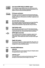
... introduces new micro-architecture features for greater performance at a given frequency, up to 50% larger L2 caches, and expanded power management capabilities for buying an ASUS® P5KPL/EPU motherboard! ASUS P5KPL/EPU 1-1 This motherboard also supports Intel® CPUs in the 45nm manufacturing process. Chapter 1 Product introduction 1.1 Welcome!
... introduces new micro-architecture features for greater performance at a given frequency, up to 50% larger L2 caches, and expanded power management capabilities for buying an ASUS® P5KPL/EPU motherboard! ASUS P5KPL/EPU 1-1 This motherboard also supports Intel® CPUs in the 45nm manufacturing process. Chapter 1 Product introduction 1.1 Welcome!
User Manual
Page 12
... home theater audio systems via the S/PDIF-out (SONY-PHILIPS Digital Interface) jack. S/PDIF digital sound ready This motherboard provides convenient connectivity to provide efficient power management for advanced operating systems. 1.3.2 Innovative ASUS features ASUS EPU ASUS EPU detects the current computer loading and intelligently adjusts the appropriate power usage in applications such as 3D gaming...
... home theater audio systems via the S/PDIF-out (SONY-PHILIPS Digital Interface) jack. S/PDIF digital sound ready This motherboard provides convenient connectivity to provide efficient power management for advanced operating systems. 1.3.2 Innovative ASUS features ASUS EPU ASUS EPU detects the current computer loading and intelligently adjusts the appropriate power usage in applications such as 3D gaming...

User Manual
Page 13
Green ASUS This motherboard and its packaging comply with quick access to the Internet and key applications before entering the Windows® OS. • The actual boot time depends ... and reboot the system, and the BIOS automatically restores the CPU parameters to overclocking failure. ASUS AI NET2 ASUS AI NET2 remotely detects the cable connection immediately after turning on the environment. ASUS P5KPL/EPU 1-3 This is in line with the ASUS vision of Hazardous Substances (RoHS). feature automatically restores the CPU default settings when the...
Green ASUS This motherboard and its packaging comply with quick access to the Internet and key applications before entering the Windows® OS. • The actual boot time depends ... and reboot the system, and the BIOS automatically restores the CPU parameters to overclocking failure. ASUS AI NET2 ASUS AI NET2 remotely detects the cable connection immediately after turning on the environment. ASUS P5KPL/EPU 1-3 This is in line with the ASUS vision of Hazardous Substances (RoHS). feature automatically restores the CPU default settings when the...

User Manual
Page 14
This is a reminder that the system is ON, in sleep mode, or in any motherboard component. Onboard LED The motherboard comes with the component. • Before you must shut down the system and unplug the power cable before removing or plugging in soft-...indicate that you install or remove any component, ensure that the ATX power supply is detached from the wall socket before you install motherboard components or change any motherboard settings. • Unplug the power cord from the power supply. The illustration below shows the location of the following precautions before ...
This is a reminder that the system is ON, in sleep mode, or in any motherboard component. Onboard LED The motherboard comes with the component. • Before you must shut down the system and unplug the power cable before removing or plugging in soft-...indicate that you install or remove any component, ensure that the ATX power supply is detached from the wall socket before you install motherboard components or change any motherboard settings. • Unplug the power cord from the power supply. The illustration below shows the location of the following precautions before ...

User Manual
Page 15
... rear part of the chassis ASUS P5KPL/EPU 1-5 Failure to the chassis. Ensure that the motherboard fits into it into the holes indicated by circles to secure the motherboard to do so can damage the motherboard. Doing so can cause you physical injury and damage motherboard components. 1.5.1 Placement direction When installing the motherboard, ensure that you unplug the...
... rear part of the chassis ASUS P5KPL/EPU 1-5 Failure to the chassis. Ensure that the motherboard fits into it into the holes indicated by circles to secure the motherboard to do so can damage the motherboard. Doing so can cause you physical injury and damage motherboard components. 1.5.1 Placement direction When installing the motherboard, ensure that you unplug the...

User Manual
Page 16
... intrusion connector (4-1 pin CHASSIS) 1-7 12. Front panel audio connector (10-1 pin AAFP) 1-4 16. CPU, chassis, and power fan connectors (4-pin CPU_FAN, 3-pin CHA_FAN, 3-pin PWR_FAN) 4. 1.5.3 Motherboard layout 20.8cm(8.2in) 1.5.4 Layout contents Connectors/Jumpers/Slots 1. LGA775 CPU socket 5. DDR2 DIMM slots 6.
... intrusion connector (4-1 pin CHASSIS) 1-7 12. Front panel audio connector (10-1 pin AAFP) 1-4 16. CPU, chassis, and power fan connectors (4-pin CPU_FAN, 3-pin CHA_FAN, 3-pin PWR_FAN) 4. 1.5.3 Motherboard layout 20.8cm(8.2in) 1.5.4 Layout contents Connectors/Jumpers/Slots 1. LGA775 CPU socket 5. DDR2 DIMM slots 6.

User Manual
Page 17
... damage is on your retailer immediately if the PnP cap is on the socket and the socket contacts are not bent. ASUS P5KPL/EPU 1-7 1.6 Central Processing Unit (CPU) The motherboard comes with the Intel® Enhanced Intel SpeedStep® Technology (EIST) and Hyper-Threading Technology. 1.6.1 Installing the CPU ... requests only if the motherboard comes with the cap on the motherboard. Before installing the CPU, ensure that the PnP cap is missing, or if you and the load lever is shipment/transit-related. • Keep the cap after installing the motherboard. ASUS will shoulder the cost...
... damage is on your retailer immediately if the PnP cap is on the socket and the socket contacts are not bent. ASUS P5KPL/EPU 1-7 1.6 Central Processing Unit (CPU) The motherboard comes with the Intel® Enhanced Intel SpeedStep® Technology (EIST) and Hyper-Threading Technology. 1.6.1 Installing the CPU ... requests only if the motherboard comes with the cap on the motherboard. Before installing the CPU, ensure that the PnP cap is missing, or if you and the load lever is shipment/transit-related. • Keep the cap after installing the motherboard. ASUS will shoulder the cost...

User Manual
Page 20
...Thermal Interface Material to the CPU heatsink or CPU before you buy a CPU separately, ensure that the four fasteners match the holes on the motherboard. Push down two fasteners at a time in a diagonal sequence to secure the heatsink and fan assembly in a push-pin design and ... introduction The illustration above is closest to the CPU fan connector. 2. Orient the heatsink and fan assembly such that you have installed the motherboard to the chassis before you use only Intel®‑certified multi‑directional heatsink and fan. • Your Intel® LGA775 heatsink...
...Thermal Interface Material to the CPU heatsink or CPU before you buy a CPU separately, ensure that the four fasteners match the holes on the motherboard. Push down two fasteners at a time in a diagonal sequence to secure the heatsink and fan assembly in a push-pin design and ... introduction The illustration above is closest to the CPU fan connector. 2. Orient the heatsink and fan assembly such that you have installed the motherboard to the chassis before you use only Intel®‑certified multi‑directional heatsink and fan. • Your Intel® LGA775 heatsink...
User Manual
Page 21
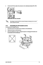
3. Connect the CPU fan cable to connect the CPU fan connector! Pull up two fasteners at a time in a diagonal sequence to plug this connector. 1.6.3 Uninstalling the CPU heatsink and fan To uninstall the CPU heatsink and fan: 1. Hardware monitoring errors can occur if you fail to disengage the heatsink and fan assembly from the connector on the motherboard labeled CPU_FAN. A B A B B A B A ASUS P5KPL/EPU 1-11 Do not forget to the connector on the motherboard. 2. Disconnect the CPU fan cable from the motherboard. Rotate each fastener counterclockwise. 3.
3. Connect the CPU fan cable to connect the CPU fan connector! Pull up two fasteners at a time in a diagonal sequence to plug this connector. 1.6.3 Uninstalling the CPU heatsink and fan To uninstall the CPU heatsink and fan: 1. Hardware monitoring errors can occur if you fail to disengage the heatsink and fan assembly from the connector on the motherboard labeled CPU_FAN. A B A B B A B A ASUS P5KPL/EPU 1-11 Do not forget to the connector on the motherboard. 2. Disconnect the CPU fan cable from the motherboard. Rotate each fastener counterclockwise. 3.

User Manual
Page 22
Rotate each fastener clockwise to ensure correct orientation when reinstalling. 1.7 System memory 1.7.1 Overview The motherboard comes with four Double Data Rate 2 (DDR2) Dual Inline Memory Modules (DIMM) sockets. Carefully remove the heatsink and fan assembly from the motherboard. 5. The figure illustrates the location of the DDR2 DIMM sockets: Channel Channel A Channel B Sockets DIMM_A1 and DIMM_A2 DIMM_B1 and DIMM_B2 1-12 Chapter 1: Product introduction 4.
Rotate each fastener clockwise to ensure correct orientation when reinstalling. 1.7 System memory 1.7.1 Overview The motherboard comes with four Double Data Rate 2 (DDR2) Dual Inline Memory Modules (DIMM) sockets. Carefully remove the heatsink and fan assembly from the motherboard. 5. The figure illustrates the location of the DDR2 DIMM sockets: Channel Channel A Channel B Sockets DIMM_A1 and DIMM_A2 DIMM_B1 and DIMM_B2 1-12 Chapter 1: Product introduction 4.

User Manual
Page 23
...not match Intel®'s On‑Die‑Termination (ODT) requirement and will be about 3GB or less. ASUS P5KPL/EPU 1-13 or - For effective use a more memory on the motherboard. • This motherboard does not support DIMMs made up of the following: - Install a 64-bit Windows® OS when you... install 4GB or more memory on the motherboard, the actual usable memory for overclocking may operate at DDR2-667. install four identical DIMMs in all four slots; install one DDR2 DIMM...
...not match Intel®'s On‑Die‑Termination (ODT) requirement and will be about 3GB or less. ASUS P5KPL/EPU 1-13 or - For effective use a more memory on the motherboard. • This motherboard does not support DIMMs made up of the following: - Install a 64-bit Windows® OS when you... install 4GB or more memory on the motherboard, the actual usable memory for overclocking may operate at DDR2-667. install four identical DIMMs in all four slots; install one DDR2 DIMM...

User Manual
Page 26
.... 1-16 Chapter 1: Product introduction Failure to do so can cause severe damage to unlock a DDR2 DIMM socket. 2. Press the retaining clips outward to both the motherboard and the components. Simultaneously press the retaining clips outward to avoid damaging the DIMM. 3. To install a DIMM: 1. Firmly insert the DIMM into a socket to unlock...
.... 1-16 Chapter 1: Product introduction Failure to do so can cause severe damage to unlock a DDR2 DIMM socket. 2. Press the retaining clips outward to both the motherboard and the components. Simultaneously press the retaining clips outward to avoid damaging the DIMM. 3. To install a DIMM: 1. Firmly insert the DIMM into a socket to unlock...

User Manual
Page 27
... read the documentation that came with the screw you removed earlier. 6. Turn on the slot. 5. Remove the system unit cover (if your motherboard is completely seated on the system and change the necessary BIOS settings, if any. Keep the screw for the expansion card. Align the card ... they support. Assign an IRQ to install expansion cards. 1.8 Expansion slots In the future, you may cause you physical injury and damage motherboard components. 1.8.1 Installing an expansion card To install an expansion card: 1. Install the software drivers for later use . ASUS P5KPL/EPU 1-17
... read the documentation that came with the screw you removed earlier. 6. Turn on the slot. 5. Remove the system unit cover (if your motherboard is completely seated on the system and change the necessary BIOS settings, if any. Keep the screw for the expansion card. Align the card ... they support. Assign an IRQ to install expansion cards. 1.8 Expansion slots In the future, you may cause you physical injury and damage motherboard components. 1.8.1 Installing an expansion card To install an expansion card: 1. Install the software drivers for later use . ASUS P5KPL/EPU 1-17
User Manual
Page 31
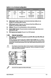
...ASUS P5KPL/EPU 1-21 USB 2.0 ports 1 and 2. Do not forget to connect the fan cables to the fan connectors on the fan connectors! Connect the fan cables to the fan connectors. USB 2.0 ports 3 and 4. Only the CPU fan supports the ASUS Q-FAN feature. PS/2 keyboard port (purple). Do not place jumper caps on the motherboard...Out Mic In Center/Subwoofer Rear Speaker Out Side Speaker Out 10. Insufficient air flow inside the system may damage the motherboard components. Audio 2, 4, 6, or 8-channel configuration Port Light Blue Lime Pink Orange Black Gray Headset 2-channel Line In ...
...ASUS P5KPL/EPU 1-21 USB 2.0 ports 1 and 2. Do not forget to connect the fan cables to the fan connectors on the fan connectors! Connect the fan cables to the fan connectors. USB 2.0 ports 3 and 4. Only the CPU fan supports the ASUS Q-FAN feature. PS/2 keyboard port (purple). Do not place jumper caps on the motherboard...Out Mic In Center/Subwoofer Rear Speaker Out Side Speaker Out 10. Insufficient air flow inside the system may damage the motherboard components. Audio 2, 4, 6, or 8-channel configuration Port Light Blue Lime Pink Orange Black Gray Headset 2-channel Line In ...

User Manual
Page 34
Connect the blue connector to the motherboard's IDE connector, then select one of device(s) Master Slave Master Slave Cable connector Black Black Gray Black or gray • Pin 20 on each Ultra ...
Connect the blue connector to the motherboard's IDE connector, then select one of device(s) Master Slave Master Slave Cable connector Black Black Gray Black or gray • Pin 20 on each Ultra ...

User Manual
Page 36
USB connectors (10-1 pin USB56, USB78) These connectors are for USB 2.0 ports. Doing so will damage the motherboard! 7. Connect the USB module cable to any of the system chassis. These USB connectors comply with USB 2.0 specification that supports up to a slot opening at ... a 1394 cable to the USB connector onboard if your chassis supports front panel USB ports. You can connect the front panel USB cable to the ASUS Q-Connector (USB, blue) first, and then install the Q-Connector (USB) to the USB connectors.
USB connectors (10-1 pin USB56, USB78) These connectors are for USB 2.0 ports. Doing so will damage the motherboard! 7. Connect the USB module cable to any of the system chassis. These USB connectors comply with USB 2.0 specification that supports up to a slot opening at ... a 1394 cable to the USB connector onboard if your chassis supports front panel USB ports. You can connect the front panel USB cable to the ASUS Q-Connector (USB, blue) first, and then install the Q-Connector (USB) to the USB connectors.


