
User Manual
Page 1
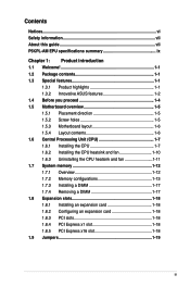
Motherboard P5KPL-AM EPU
Motherboard P5KPL-AM EPU
User Manual
Page 3
Contents Notices...vi Safety information vii About this guide vii P5KPL-AM EPU specifications summary ix Chapter 1: Product introduction 1.1 Welcome 1-1 1.2 Package contents 1-1 1.3 Special features 1-1 1.3.1 Product highlights 1-1 1.3.2 Innovative ASUS features 1-2 1.4 Before you proceed 1-4 1.5 Motherboard overview 1-5 1.5.1 Placement direction 1-5 1.5.2 Screw holes 1-5 1.5.3 Motherboard layout 1-6 1.5.4 Layout contents 1-6 1.6 Central Processing Unit (CPU 1-7 1.6.1 Installing the CPU 1-7 1.6.2 Installing the CPU heatsink and fan 1-10...
Contents Notices...vi Safety information vii About this guide vii P5KPL-AM EPU specifications summary ix Chapter 1: Product introduction 1.1 Welcome 1-1 1.2 Package contents 1-1 1.3 Special features 1-1 1.3.1 Product highlights 1-1 1.3.2 Innovative ASUS features 1-2 1.4 Before you proceed 1-4 1.5 Motherboard overview 1-5 1.5.1 Placement direction 1-5 1.5.2 Screw holes 1-5 1.5.3 Motherboard layout 1-6 1.5.4 Layout contents 1-6 1.6 Central Processing Unit (CPU 1-7 1.6.1 Installing the CPU 1-7 1.6.2 Installing the CPU heatsink and fan 1-10...
User Manual
Page 6
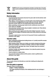
...device must accept any interference received including interference that interference will not occur in municipal waste. DO NOT throw the motherboard in accordance with FCC regulations. Notices Federal Communications Commission Statement This device complies with the REACH (Registration, Evaluation, ...Authorisation, and Restriction of Chemicals) regulatory framework, we published the chemical substances in our products at ASUS REACH website at http://green.asus.com/english/REACH.htm. Canadian Department of Communications Statement This digital apparatus does not exceed the Class ...
...device must accept any interference received including interference that interference will not occur in municipal waste. DO NOT throw the motherboard in accordance with FCC regulations. Notices Federal Communications Commission Statement This device complies with the REACH (Registration, Evaluation, ...Authorisation, and Restriction of Chemicals) regulatory framework, we published the chemical substances in our products at ASUS REACH website at http://green.asus.com/english/REACH.htm. Canadian Department of Communications Statement This digital apparatus does not exceed the Class ...
User Manual
Page 7
... and the power cables are not damaged. Contact a qualified service technician or your retailer. Operation safety • Before installing the motherboard and adding devices on a stable surface. • If you encounter technical problems with the package. • Before using the product...it supports. vii This symbol of the electrical outlet you add a device. • Before connecting or removing signal cables from the motherboard, ensure that came with the product, contact a qualified service technician or your retailer. Safety information Electrical safety • To prevent...
... and the power cables are not damaged. Contact a qualified service technician or your retailer. Operation safety • Before installing the motherboard and adding devices on a stable surface. • If you encounter technical problems with the package. • Before using the product...it supports. vii This symbol of the electrical outlet you add a device. • Before connecting or removing signal cables from the motherboard, ensure that came with the product, contact a qualified service technician or your retailer. Safety information Electrical safety • To prevent...
User Manual
Page 11
..., multimedia, and enthusiastic gamers with the list below. 1.2 Package contents Check your motherboard package for buying an ASUS® P5KPL-AM EPU motherboard! ASUS P5KPL-AM EPU 1-1 Thank you start installing the motherboard, and hardware devices on it another standout in the 45nm manufacturing process. This motherboard also supports Intel® CPUs in the long line of the above items...
..., multimedia, and enthusiastic gamers with the list below. 1.2 Package contents Check your motherboard package for buying an ASUS® P5KPL-AM EPU motherboard! ASUS P5KPL-AM EPU 1-1 Thank you start installing the motherboard, and hardware devices on it another standout in the 45nm manufacturing process. This motherboard also supports Intel® CPUs in the long line of the above items...
User Manual
Page 12
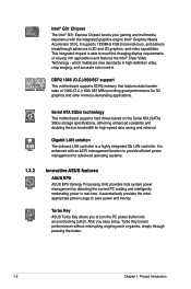
...graphics and other memory-demanding applications. After you to provide efficient power management for advanced operating systems. 1.3.2 Innovative ASUS features ASUS EPU ASUS EPU (Energy Processing Unit) provides total system power management by detecting the current PC loading and intelligently moderating power in... color control. This integrated chipset is able to save power and money. DDR2 1066 (O.C.)/800/667 support This motherboard supports DDR2 memory that features data transfer rates of visually rich applications and features the Intel® Clear Video Technology...
...graphics and other memory-demanding applications. After you to provide efficient power management for advanced operating systems. 1.3.2 Innovative ASUS features ASUS EPU ASUS EPU (Energy Processing Unit) provides total system power management by detecting the current PC loading and intelligently moderating power in... color control. This integrated chipset is able to save power and money. DDR2 1066 (O.C.)/800/667 support This motherboard supports DDR2 memory that features data transfer rates of visually rich applications and features the Intel® Clear Video Technology...
User Manual
Page 13
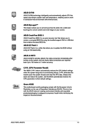
... their default settings. ASUS P5KPL-AM EPU 1-3 ASUS EZ Flash 2 ASUS EZ Flash 2 is a utility that contains the latest BIOS file. C.P.R. ASUS Q-FAN ASUS Q-FAN technology intelligently and automatically adjusts CPU fan speed according to system load and temperature, enabling users to work in line with the ASUS vision of Hazardous Substances (RoHS). Green ASUS This motherboard and its packaging...
... their default settings. ASUS P5KPL-AM EPU 1-3 ASUS EZ Flash 2 ASUS EZ Flash 2 is a utility that contains the latest BIOS file. C.P.R. ASUS Q-FAN ASUS Q-FAN technology intelligently and automatically adjusts CPU fan speed according to system load and temperature, enabling users to work in line with the ASUS vision of Hazardous Substances (RoHS). Green ASUS This motherboard and its packaging...

User Manual
Page 14
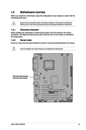
...the onboard LED. 1-4 Chapter 1: Product introduction The illustration below shows the location of the following precautions before you install motherboard components or change any motherboard settings. • Unplug the power cord from the wall socket before removing or plugging in any component, ensure that...8226; Hold components by the edges to avoid touching the ICs on them. • Whenever you install or remove any motherboard component. Onboard LED The motherboard comes with the component. • Before you uninstall any component, place it on a grounded antistatic pad or in ...
...the onboard LED. 1-4 Chapter 1: Product introduction The illustration below shows the location of the following precautions before you install motherboard components or change any motherboard settings. • Unplug the power cord from the wall socket before removing or plugging in any component, ensure that...8226; Hold components by the edges to avoid touching the ICs on them. • Whenever you install or remove any motherboard component. Onboard LED The motherboard comes with the component. • Before you uninstall any component, place it on a grounded antistatic pad or in ...
User Manual
Page 15
... it into the chassis in the correct orientation. Do not overtighten the screws! Place this side towards the rear of the chassis ASUS P5KPL-AM EPU 1-5 1.5 Motherboard overview Before you install the motherboard, study the configuration of your chassis to ensure that you place it . Doing so can cause you unplug the power cord before...
... it into the chassis in the correct orientation. Do not overtighten the screws! Place this side towards the rear of the chassis ASUS P5KPL-AM EPU 1-5 1.5 Motherboard overview Before you install the motherboard, study the configuration of your chassis to ensure that you place it . Doing so can cause you unplug the power cord before...
User Manual
Page 16
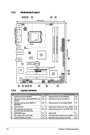
... connector (4-1 pin SPDIF_OUT) 1-23 6. DDR2 DIMM sockets 1-12 14. Onboard LED 1-4 7. Serial ATA connectors (7-pin SATA1-4) 1-24 ATX12V) 3. USB connectors (10-1 pin USB56, USB78) 1-27 4. 1.5.3 Motherboard layout 1.5.4 Layout contents Connectors/Jumpers/Slots Page Connectors/Jumpers/Slots Page 1. System panel connector (10-1 pin F_PANEL) 1-26 5. Intel CPU socket 1-7 12. Keyboard power (3-pin...
... connector (4-1 pin SPDIF_OUT) 1-23 6. DDR2 DIMM sockets 1-12 14. Onboard LED 1-4 7. Serial ATA connectors (7-pin SATA1-4) 1-24 ATX12V) 3. USB connectors (10-1 pin USB56, USB78) 1-27 4. 1.5.3 Motherboard layout 1.5.4 Layout contents Connectors/Jumpers/Slots Page Connectors/Jumpers/Slots Page 1. System panel connector (10-1 pin F_PANEL) 1-26 5. Intel CPU socket 1-7 12. Keyboard power (3-pin...
User Manual
Page 17
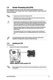
... misplacement/loss/incorrect removal of repair only if the damage is on the motherboard. ASUS P5KPL-AM EPU 1-7 ASUS will process Return Merchandise Authorization (RMA) requests only if the motherboard comes with the cap on the socket and the socket contacts are not bent. ASUS will shoulder the cost of the PnP cap. Before installing the CPU...
... misplacement/loss/incorrect removal of repair only if the damage is on the motherboard. ASUS P5KPL-AM EPU 1-7 ASUS will process Return Merchandise Authorization (RMA) requests only if the motherboard comes with the cap on the socket and the socket contacts are not bent. ASUS will shoulder the cost of the PnP cap. Before installing the CPU...

User Manual
Page 20
... assembly may differ, but the installation steps and functions should remain the same. A B A B B A 1 1 B A The type of the installed CPU, ensuring that you have installed the motherboard to the CPU fan connector. 2. Push down two fasteners at a time in a diagonal sequence to secure the heatsink and fan assembly in a push-pin design... above is closest to the chassis before you purchased a separate CPU heatsink and fan assembly, ensure that the four fasteners match the holes on the motherboard. If you install the CPU fan and heatsink assembly.
... assembly may differ, but the installation steps and functions should remain the same. A B A B B A 1 1 B A The type of the installed CPU, ensuring that you have installed the motherboard to the CPU fan connector. 2. Push down two fasteners at a time in a diagonal sequence to secure the heatsink and fan assembly in a push-pin design... above is closest to the chassis before you purchased a separate CPU heatsink and fan assembly, ensure that the four fasteners match the holes on the motherboard. If you install the CPU fan and heatsink assembly.
User Manual
Page 21
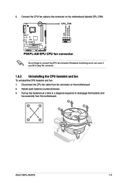
Do not forget to plug this connector. 1.6.3 Uninstalling the CPU heatsink and fan To uninstall the CPU heatsink and fan: 1. 3. Hardware monitoring errors can occur if you fail to connect the CPU fan connector! Pull up two fasteners at a time in a diagonal sequence to the connector on the motherboard. 2. A B A B B A B A ASUS P5KPL-AM EPU 1-11 Connect the CPU fan cable to disengage the heatsink and fan assembly from the connector on the motherboard labeled CPU_FAN. Disconnect the CPU fan cable from the motherboard. Rotate each fastener counterclockwise. 3.
Do not forget to plug this connector. 1.6.3 Uninstalling the CPU heatsink and fan To uninstall the CPU heatsink and fan: 1. 3. Hardware monitoring errors can occur if you fail to connect the CPU fan connector! Pull up two fasteners at a time in a diagonal sequence to the connector on the motherboard. 2. A B A B B A B A ASUS P5KPL-AM EPU 1-11 Connect the CPU fan cable to disengage the heatsink and fan assembly from the connector on the motherboard labeled CPU_FAN. Disconnect the CPU fan cable from the motherboard. Rotate each fastener counterclockwise. 3.

User Manual
Page 22
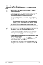
Carefully remove the heatsink and fan assembly from the motherboard. 5. 4. The figure illustrates the location of the DDR2 DIMM sockets: Channel Channel A Channel B Sockets DIMM_A1 DIMM_B1 1-12 Chapter 1: Product introduction Rotate each fastener clockwise to ensure correct orientation when reinstalling. 1.7 System memory 1.7.1 Overview The motherboard comes with two Double Data Rate 2 (DDR2) Dual Inline Memory Modules (DIMM) sockets.
Carefully remove the heatsink and fan assembly from the motherboard. 5. 4. The figure illustrates the location of the DDR2 DIMM sockets: Channel Channel A Channel B Sockets DIMM_A1 DIMM_B1 1-12 Chapter 1: Product introduction Rotate each fastener clockwise to ensure correct orientation when reinstalling. 1.7 System memory 1.7.1 Overview The motherboard comes with two Double Data Rate 2 (DDR2) Dual Inline Memory Modules (DIMM) sockets.
User Manual
Page 23
... lower latency, adjust the memory timing manually. ASUS P5KPL-AM EPU 1-13 If this happens, contact your memory vendor to check the ODT value. • Due to run at DDR2-667 by default setting. If you install 4GB or more memory on the motherboard. • This motherboard does not support DIMMs made up to install...
... lower latency, adjust the memory timing manually. ASUS P5KPL-AM EPU 1-13 If this happens, contact your memory vendor to check the ODT value. • Due to run at DDR2-667 by default setting. If you install 4GB or more memory on the motherboard. • This motherboard does not support DIMMs made up to install...
User Manual
Page 27
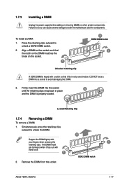
...to unlock the DIMM. 2 Support the DIMM lightly with your fingers when pressing the retaining clips. Press the retaining clips outward to both the motherboard and the components. The DIMM might get damaged when it fits in place 3 and the DIMM is keyed with extra force. 1 1 ...the notch on the DIMM matches the break on the socket. 1 2 DDR2 DIMM notch 1 Unlocked retaining clip A DDR2 DIMM is properly seated. ASUS P5KPL-AM EPU 1-17 1.7.3 Installing a DIMM Unplug the power supply before adding or removing DIMMs or other system components. To install a DIMM: 1. Remove the ...
...to unlock the DIMM. 2 Support the DIMM lightly with your fingers when pressing the retaining clips. Press the retaining clips outward to both the motherboard and the components. The DIMM might get damaged when it fits in place 3 and the DIMM is keyed with extra force. 1 1 ...the notch on the DIMM matches the break on the socket. 1 2 DDR2 DIMM notch 1 Unlocked retaining clip A DDR2 DIMM is properly seated. ASUS P5KPL-AM EPU 1-17 1.7.3 Installing a DIMM Unplug the power supply before adding or removing DIMMs or other system components. To install a DIMM: 1. Remove the ...
User Manual
Page 28
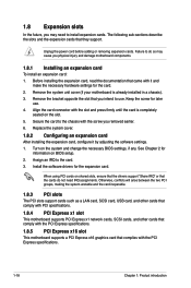
... adding or removing expansion cards. Turn on the slot. 5. 1.8 Expansion slots In the future, you may cause you physical injury and damage motherboard components. 1.8.1 Installing an expansion card To install an expansion card: 1. The following sub‑sections describe the slots and the expansion cards that... as a LAN card, SCSI card, USB card, and other cards that comply with PCI specifications. 1.8.4 PCI Express x1 slot This motherboard supports PCI Express x1 network cards, SCSI cards, and other cards that comply with the PCI Express specifications. 1.8.5 PCI Express x16 slot This...
... adding or removing expansion cards. Turn on the slot. 5. 1.8 Expansion slots In the future, you may cause you physical injury and damage motherboard components. 1.8.1 Installing an expansion card To install an expansion card: 1. The following sub‑sections describe the slots and the expansion cards that... as a LAN card, SCSI card, USB card, and other cards that comply with PCI specifications. 1.8.4 PCI Express x1 slot This motherboard supports PCI Express x1 network cards, SCSI cards, and other cards that comply with the PCI Express specifications. 1.8.5 PCI Express x16 slot This...
User Manual
Page 32
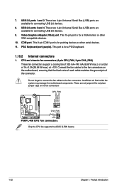
... monitor or other serial devices. 11. This port is for a PS/2 keyboard. 1.10.2 Internal connectors 1. Only the CPU fan supports the ASUS Q-FAN feature. 1-22 Chapter 1: Product introduction These two 4-pin Universal Serial Bus (USB) ports are available for connecting USB 2.0 devices. 8.... This 9-pin COM1 port is for pointing devices or other VGA-compatible devices. 10. Insufficient air flow inside the system may damage the motherboard components. PS/2 Keyboard port (purple). These are available for connecting USB 2.0 devices. 9. 7. Do not forget to connect the fan cables...
... monitor or other serial devices. 11. This port is for a PS/2 keyboard. 1.10.2 Internal connectors 1. Only the CPU fan supports the ASUS Q-FAN feature. 1-22 Chapter 1: Product introduction These two 4-pin Universal Serial Bus (USB) ports are available for connecting USB 2.0 devices. 8.... This 9-pin COM1 port is for pointing devices or other VGA-compatible devices. 10. Insufficient air flow inside the system may damage the motherboard components. PS/2 Keyboard port (purple). These are available for connecting USB 2.0 devices. 9. 7. Do not forget to connect the fan cables...
User Manual
Page 35
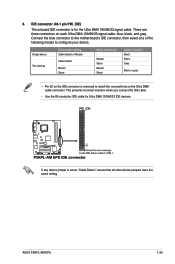
... Mode of the following modes to match the covered hole on the Ultra DMA cable connector. ASUS P5KPL-AM EPU 1-25 6. If any device jumper is removed to configure your device. Connect the blue connector to the motherboard's IDE connector, then select one of device(s) Master Slave Master Slave Cable connector Black Black Gray...
... Mode of the following modes to match the covered hole on the Ultra DMA cable connector. ASUS P5KPL-AM EPU 1-25 6. If any device jumper is removed to configure your device. Connect the blue connector to the motherboard's IDE connector, then select one of device(s) Master Slave Master Slave Cable connector Black Black Gray...
User Manual
Page 37
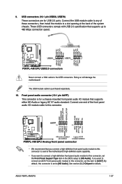
...) This connector is set the Front Panel Support Type item in the BIOS setup to [AC97]. Connect the USB module cable to any of the motherboard's high-definition audio capability. • If you want to connect a high-definition front panel audio module to this connector, set the item to [HD Audio... connection speed. 9. These USB connectors comply with USB 2.0 specification that supports either HD Audio or legacy AC`97 audio standard. Doing so will damage the motherboard! The USB module cable is purchased separately. 10. ASUS P5KPL-AM EPU 1-27
...) This connector is set the Front Panel Support Type item in the BIOS setup to [AC97]. Connect the USB module cable to any of the motherboard's high-definition audio capability. • If you want to connect a high-definition front panel audio module to this connector, set the item to [HD Audio... connection speed. 9. These USB connectors comply with USB 2.0 specification that supports either HD Audio or legacy AC`97 audio standard. Doing so will damage the motherboard! The USB module cable is purchased separately. 10. ASUS P5KPL-AM EPU 1-27


