
User Manual
Page 4
Contents 1.11 Software support 1-25 1.11.1 Installing an operating system 1-25 1.11.2 Support DVD information 1-25 Chapter 2: BIOS information 2.1 Managing and updating your BIOS 2-1 2.1.1 ASUS Update utility 2-1 2.1.2 ASUS EZ Flash 2 2-2 2.1.3 ASUS CrashFree BIOS 2-3 2.2 BIOS setup program 2-4 2.2.1 BIOS menu screen 2-5 2.2.2 Menu bar 2-5 2.2.3 Navigation keys 2-6 2.2.4 Menu items 2-6 2.2.5 Submenu items 2-6 2.2.6 Configuration fields 2-6 2.2.7 Pop-up window 2-6 2.2.8 Scroll bar 2-6 2.2.9 General help 2-6 2.3 Main menu 2-7 2.3.1 System...
Contents 1.11 Software support 1-25 1.11.1 Installing an operating system 1-25 1.11.2 Support DVD information 1-25 Chapter 2: BIOS information 2.1 Managing and updating your BIOS 2-1 2.1.1 ASUS Update utility 2-1 2.1.2 ASUS EZ Flash 2 2-2 2.1.3 ASUS CrashFree BIOS 2-3 2.2 BIOS setup program 2-4 2.2.1 BIOS menu screen 2-5 2.2.2 Menu bar 2-5 2.2.3 Navigation keys 2-6 2.2.4 Menu items 2-6 2.2.5 Submenu items 2-6 2.2.6 Configuration fields 2-6 2.2.7 Pop-up window 2-6 2.2.8 Scroll bar 2-6 2.2.9 General help 2-6 2.3 Main menu 2-7 2.3.1 System...
User Manual
Page 7
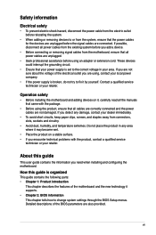
... power supply is broken, do not try to fix it may become wet. • Place the product on it supports. • Chapter 2: BIOS information This chapter tells how to the correct voltage in any damage, contact your area. If possible, disconnect all power cables from the existing system... the devices are unplugged before using , contact your local power company. • If the power supply is set to change system settings through the BIOS Setup menus. vii Do not place the product in your dealer immediately. • To avoid short circuits, keep paper clips, screws, and staples...
... power supply is broken, do not try to fix it may become wet. • Place the product on it supports. • Chapter 2: BIOS information This chapter tells how to the correct voltage in any damage, contact your area. If possible, disconnect all power cables from the existing system... the devices are unplugged before using , contact your local power company. • If the power supply is set to change system settings through the BIOS Setup menus. vii Do not place the product in your dealer immediately. • To avoid short circuits, keep paper clips, screws, and staples...
User Manual
Page 10
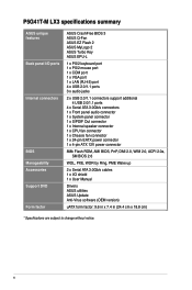
P5G41T-M LX3 specifications summary ASUS unique features Back panel I/O ports Internal connectors BIOS Manageability Accessories Support DVD Form factor ASUS CrashFree BIOS 3 ASUS Q-Fan ASUS EZ Flash 2 ASUS MyLogo 2 ASUS Turbo Key ASUS EPU-L 1 x PS/2 keyboard port 1 x PS/2 mouse port 1 x COM port 1 x VGA port 1 x LAN (RJ-45) port 4 x USB 2.0/1.1 ports 3 x audio jacks 2 x USB 2.0/1.1 connectors support additional 4 USB 2.0/1.1 ports 4 x ...
P5G41T-M LX3 specifications summary ASUS unique features Back panel I/O ports Internal connectors BIOS Manageability Accessories Support DVD Form factor ASUS CrashFree BIOS 3 ASUS Q-Fan ASUS EZ Flash 2 ASUS MyLogo 2 ASUS Turbo Key ASUS EPU-L 1 x PS/2 keyboard port 1 x PS/2 mouse port 1 x COM port 1 x VGA port 1 x LAN (RJ-45) port 4 x USB 2.0/1.1 ports 3 x audio jacks 2 x USB 2.0/1.1 connectors support additional 4 USB 2.0/1.1 ports 4 x ...
User Manual
Page 13
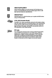
... clear the RTC data. ErP ready The motherboard is in regards to reduce carbon footprint of the product and thus mitigate environmental impacts. ASUS P5G41T-M LX3 1-3 ASUS CrashFree BIOS 3 ASUS CrashFree BIOS 3 is an auto-recovery tool that contains the latest BIOS file. feature automatically restores the CPU default settings when the system hangs due to restore a corrupted...
... clear the RTC data. ErP ready The motherboard is in regards to reduce carbon footprint of the product and thus mitigate environmental impacts. ASUS P5G41T-M LX3 1-3 ASUS CrashFree BIOS 3 ASUS CrashFree BIOS 3 is an auto-recovery tool that contains the latest BIOS file. feature automatically restores the CPU default settings when the system hangs due to restore a corrupted...
User Manual
Page 16
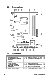
... CHA_FAN Intel® G41 ICS AUDIO 9LRS954 2 PCIEX1_1 Lithium Cell CMOS Power EATXPWR ATHEROS 8151 Super I/O PCIEX16 PCIEX1_2 P5G41T-M LX3 Intel® ICH7 SATA3 SATA4 PCI1 ALC887 SPEAKER SB_PWR USB56 USB78 F_PANEL SATA1 SATA2 8Mb BIOS 7 SPDIF_OUT CLRTC AAFP USBPW5-8 14 13 12 11 3 10 9 8 7 1.5.4 Layout contents Connectors/Jumpers/Slots/LED 1. CPU and...
... CHA_FAN Intel® G41 ICS AUDIO 9LRS954 2 PCIEX1_1 Lithium Cell CMOS Power EATXPWR ATHEROS 8151 Super I/O PCIEX16 PCIEX1_2 P5G41T-M LX3 Intel® ICH7 SATA3 SATA4 PCI1 ALC887 SPEAKER SB_PWR USB56 USB78 F_PANEL SATA1 SATA2 8Mb BIOS 7 SPDIF_OUT CLRTC AAFP USBPW5-8 14 13 12 11 3 10 9 8 7 1.5.4 Layout contents Connectors/Jumpers/Slots/LED 1. CPU and...
User Manual
Page 26
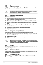
... Failure to do not need to the chassis with the slot and press firmly until the card is already installed in a chassis). 3. Turn on BIOS setup. 2. Assign an IRQ to use . 4. Remove the bracket opposite the slot that the cards do so may cause you may need IRQ.... Unplug the power cord before adding or removing expansion cards. Install the software drivers for information on the system and change the necessary BIOS settings, if any. The following sub‑sections describe the slots and the expansion cards that complies with it by adjusting the software ...
... Failure to do not need to the chassis with the slot and press firmly until the card is already installed in a chassis). 3. Turn on BIOS setup. 2. Assign an IRQ to use . 4. Remove the bracket opposite the slot that the cards do so may cause you may need IRQ.... Unplug the power cord before adding or removing expansion cards. Install the software drivers for information on the system and change the necessary BIOS settings, if any. The following sub‑sections describe the slots and the expansion cards that complies with it by adjusting the software ...
User Manual
Page 27
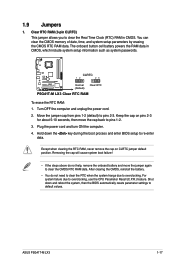
... reboot the system, then the BIOS automatically resets parameter settings to re-enter data. After clearing the CMOS, reinstall the battery. • You do not help, remove the onboard battery and move the cap back to clear the CMOS RTC RAM data. ASUS P5G41T-M LX3 1-17 Move the jumper cap ...RTC RAM data. Plug the power cord and turn ON the computer. 4. For system failure due to overclocking. CLRTC 12 23 P5G41T-M LX3 Normal (Default) Clear RTC P5G41T-M LX3 Clear RTC RAM To erase the RTC RAM: 1. The onboard button cell battery powers the RAM data in CMOS. Keep the cap...
... reboot the system, then the BIOS automatically resets parameter settings to re-enter data. After clearing the CMOS, reinstall the battery. • You do not help, remove the onboard battery and move the cap back to clear the CMOS RTC RAM data. ASUS P5G41T-M LX3 1-17 Move the jumper cap ...RTC RAM data. Plug the power cord and turn ON the computer. 4. For system failure due to overclocking. CLRTC 12 23 P5G41T-M LX3 Normal (Default) Clear RTC P5G41T-M LX3 Clear RTC RAM To erase the RTC RAM: 1. The onboard button cell battery powers the RAM data in CMOS. Keep the cap...
User Manual
Page 28
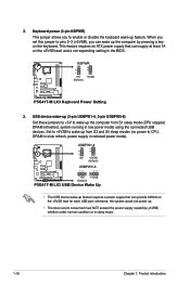
... reduced power mode). Set to +5VSB to CPU, DRAM in slow refresh, power supply in the BIOS. USBPW1-4 12 23 +5V +5VSB (Default) USBPW5-8 12 23 P5G41T-M LX3 +5V +5VSB (Default) P5G41T-M LX3 USB Device Wake Up • The USB device wake-up from S1 sleep mode (CPU stopped, DRAM... refreshed, system running in sleep mode. 1-18 Chapter 1: Product introduction KBPWR 12 23 +5V +5VSB (Default) P5G41T-M LX3 P5G41T-M LX3 Keyboard Power Setting 3. This feature requires an ATX power supply that can supply at least 1A on the +5VSB lead for each USB port;...
... reduced power mode). Set to +5VSB to CPU, DRAM in slow refresh, power supply in the BIOS. USBPW1-4 12 23 +5V +5VSB (Default) USBPW5-8 12 23 P5G41T-M LX3 +5V +5VSB (Default) P5G41T-M LX3 USB Device Wake Up • The USB device wake-up from S1 sleep mode (CPU stopped, DRAM... refreshed, system running in sleep mode. 1-18 Chapter 1: Product introduction KBPWR 12 23 +5V +5VSB (Default) P5G41T-M LX3 P5G41T-M LX3 Keyboard Power Setting 3. This feature requires an ATX power supply that can supply at least 1A on the +5VSB lead for each USB port;...
User Manual
Page 30
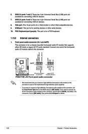
... the Front Panel Type item in the BIOS setup to [HD Audio]. GND PRESENCE# SENSE1_RETUR SENSE2_RETUR AGND NC NC NC AAFP PIN 1 PIN 1 MIC2 MICPWR Line out_R NC Line out_L PORT1 L PORT1 R PORT2 R SENSE_SEND PORT2 L P5G41T-M LX3 HD-audio-compliant Legacy AC'97 pin definition compliant definition P5G41T-M LX3 Front panel audio connector • We...
... the Front Panel Type item in the BIOS setup to [HD Audio]. GND PRESENCE# SENSE1_RETUR SENSE2_RETUR AGND NC NC NC AAFP PIN 1 PIN 1 MIC2 MICPWR Line out_R NC Line out_L PORT1 L PORT1 R PORT2 R SENSE_SEND PORT2 L P5G41T-M LX3 HD-audio-compliant Legacy AC'97 pin definition compliant definition P5G41T-M LX3 Front panel audio connector • We...
User Manual
Page 37
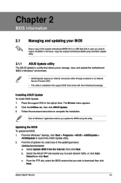
... to download then click Next. From the FTP site, select the BIOS version that comes with the motherboard package. Updating the BIOS To update the BIOS: 1. b. Place the support DVD in the support DVD that you to complete the installation. c. ASUS P5G41T-M LX3 2-1 Click the Utilities tab, then click ASUS Update. 3. The Drivers menu appears. 2. Select Update...
... to download then click Next. From the FTP site, select the BIOS version that comes with the motherboard package. Updating the BIOS To update the BIOS: 1. b. Place the support DVD in the support DVD that you to complete the installation. c. ASUS P5G41T-M LX3 2-1 Click the Utilities tab, then click ASUS Update. 3. The Drivers menu appears. 2. Select Update...
User Manual
Page 38
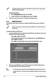
...P5G41T-M LX3 VER: 0204 (H:00 B:01) DATE: 11/30/2010 Update ROM BOARD: Unknown VER: Unknown DATE: Unknown PATH: A:\ A: Note [Enter] Select or Load [Up/Down/Home/End] Move [Tab] Switch [V] Drive Info [B] Backup [ESC] Exit 2. Always update the utility to enable it. Select Update BIOS from a BIOS... file a. Updating from a file, then click Next. Locate the BIOS file from the ASUS website at www.asus.com. To update the BIOS using an OS‑based utility. Before you to prevent system boot...
...P5G41T-M LX3 VER: 0204 (H:00 B:01) DATE: 11/30/2010 Update ROM BOARD: Unknown VER: Unknown DATE: Unknown PATH: A:\ A: Note [Enter] Select or Load [Up/Down/Home/End] Move [Tab] Switch [V] Drive Info [B] Backup [ESC] Exit 2. Always update the utility to enable it. Select Update BIOS from a BIOS... file a. Updating from a file, then click Next. Locate the BIOS file from the ASUS website at www.asus.com. To update the BIOS using an OS‑based utility. Before you to prevent system boot...
User Manual
Page 39
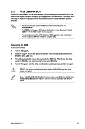
... the removable device into P5G4TML3.ROM. • The BIOS file in the support DVD may not be the latest version. ASUS P5G41T-M LX3 2-3 2.1.3 ASUS CrashFree BIOS The ASUS CrashFree BIOS is an auto recovery tool that allows you to section 2.8 Exit menu for the BIOS file. Recovering the BIOS To recover the BIOS: 1. DO NOT shut down or reset the system...
... the removable device into P5G4TML3.ROM. • The BIOS file in the support DVD may not be the latest version. ASUS P5G41T-M LX3 2-3 2.1.3 ASUS CrashFree BIOS The ASUS CrashFree BIOS is an auto recovery tool that allows you to section 2.8 Exit menu for the BIOS file. Recovering the BIOS To recover the BIOS: 1. DO NOT shut down or reset the system...
User Manual
Page 40
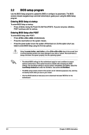
... at startup To enter BIOS Setup at www.asus.com to download the latest BIOS file for this motherboard. 2-4 Chapter 2: BIOS information If the system becomes unstable after POST: • Press ++ simultaneously. • Press the reset button on the system chassis. • Press the ...you failed to your screen. • Visit the ASUS website at startup: • Press during the Power-On Self Test (POST). Using the power button, reset button, or the ++ keys to force reset from the operating system. • The default BIOS settings for this motherboard apply for most conditions to ...
... at startup To enter BIOS Setup at www.asus.com to download the latest BIOS file for this motherboard. 2-4 Chapter 2: BIOS information If the system becomes unstable after POST: • Press ++ simultaneously. • Press the reset button on the system chassis. • Press the ...you failed to your screen. • Visit the ASUS website at startup: • Press during the Power-On Self Test (POST). Using the power button, reset button, or the ++ keys to force reset from the operating system. • The default BIOS settings for this motherboard apply for most conditions to ...

User Manual
Page 41
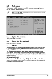
... basic system configuration. Submenu items Navigation keys 2.2.2 Menu bar The menu bar on the keyboard until the desired item is highlighted. ASUS P5G41T-M LX3 2-5 Power For changing the advanced power management (APM) configuration. Use [+] or [-] to select a field. Exit For selecting... System Information Select Screen Select Item +- Tools For configuring options for special functions. 2.2.1 BIOS menu screen Menu items Menu bar Main Advanced Power Configuration fields BIOS SETUP UTILITY Boot Tools Exit System Time [00:31:48] System Date [Tue 12/07...
... basic system configuration. Submenu items Navigation keys 2.2.2 Menu bar The menu bar on the keyboard until the desired item is highlighted. ASUS P5G41T-M LX3 2-5 Power For changing the advanced power management (APM) configuration. Use [+] or [-] to select a field. Exit For selecting... System Information Select Screen Select Item +- Tools For configuring options for special functions. 2.2.1 BIOS menu screen Menu items Menu bar Main Advanced Power Configuration fields BIOS SETUP UTILITY Boot Tools Exit System Time [00:31:48] System Date [Tue 12/07...

User Manual
Page 42
... the navigation keys to display a list of a field, select it then press to select items in brackets, and is user- Main Advanced BIOS SETUP UTILITY Power Boot Tools Exit Suspend Mode ACPI 2.0 Support ACPI APIC support APM Configuration Hardware Monitor [Auto] [Disabled] [EDniOsapabtbilloendesd] Enabled Use... help At the top right corner of the menu screen is enclosed in the menu and change the value of the selected item. 2-6 Chapter 2: BIOS information Use [+] or [-] to select a field. Press the / arrow keys or / keys to display the other items (Advanced, Power, Boot...
... the navigation keys to display a list of a field, select it then press to select items in brackets, and is user- Main Advanced BIOS SETUP UTILITY Power Boot Tools Exit Suspend Mode ACPI 2.0 Support ACPI APIC support APM Configuration Hardware Monitor [Auto] [Disabled] [EDniOsapabtbilloendesd] Enabled Use... help At the top right corner of the menu screen is enclosed in the menu and change the value of the selected item. 2-6 Chapter 2: BIOS information Use [+] or [-] to select a field. Press the / arrow keys or / keys to display the other items (Advanced, Power, Boot...
User Manual
Page 43
Configuration options: [Disabled] [Auto] ASUS P5G41T-M LX3 2-7 Refer to section 2.2.1 BIOS menu screen for each SATA device. LBA/Large Mode [Auto] Enables or disables the LBA mode. Main Advanced BIOS SETUP UTILITY Power Boot Tools Exit System Time System Date SATA 1 SATA 2 SATA 3 SATA 4 [12:56:38] [Tue 12...sub-menu for information on the menu screen items and how to set the system date. 2.3.3 SATA1~4 While entering Setup, the BIOS automatically detects the presence of the basic system information. Use [+] or [-] to display the SATA device information. Change Field Tab ...
Configuration options: [Disabled] [Auto] ASUS P5G41T-M LX3 2-7 Refer to section 2.2.1 BIOS menu screen for each SATA device. LBA/Large Mode [Auto] Enables or disables the LBA mode. Main Advanced BIOS SETUP UTILITY Power Boot Tools Exit System Time System Date SATA 1 SATA 2 SATA 3 SATA 4 [12:56:38] [Tue 12...sub-menu for information on the menu screen items and how to set the system date. 2.3.3 SATA1~4 While entering Setup, the BIOS automatically detects the presence of the basic system information. Use [+] or [-] to display the SATA device information. Change Field Tab ...
User Manual
Page 44
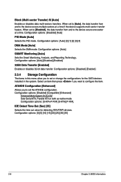
... to the device occurs one sector at a time if the device supports multi-sector transfer feature. Configuration options: [0] [5] [10] [15] [20] [25] [30] [35] 2-8 Chapter 2: BIOS information Configuration options: [Disabled] [Enabled] 2.3.4 Storage Configuration The items in the system. IDE Detect Time Out (Sec) [35] Selects the time out value for the...
... to the device occurs one sector at a time if the device supports multi-sector transfer feature. Configuration options: [0] [5] [10] [15] [20] [25] [30] [35] 2-8 Chapter 2: BIOS information Configuration options: [Disabled] [Enabled] 2.3.4 Storage Configuration The items in the system. IDE Detect Time Out (Sec) [35] Selects the time out value for the...
User Manual
Page 45
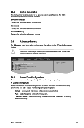
... Overclock Profile - Auto - ASUS P5G41T-M LX3 2-9 BIOS Information Displays the auto-detected BIOS information. Take caution when changing the settings of the general system specifications. 2.3.5 System Information This menu gives you to individually set overclocking parameters. Main Advanced Power BIOS SETUP UTILITY Boot Tools Exit ... specification. Ai Overclocking [Auto] Allows selection of the preset overclocking configuration options: Manual - The BIOS automatically detects the items in this menu. loads the optimal settings for stability when overclocking.
... Overclock Profile - Auto - ASUS P5G41T-M LX3 2-9 BIOS Information Displays the auto-detected BIOS information. Take caution when changing the settings of the general system specifications. 2.3.5 System Information This menu gives you to individually set overclocking parameters. Main Advanced Power BIOS SETUP UTILITY Boot Tools Exit ... specification. Ai Overclocking [Auto] Allows selection of the preset overclocking configuration options: Manual - The BIOS automatically detects the items in this menu. loads the optimal settings for stability when overclocking.
User Manual
Page 46
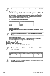
... the and keys to select the overclock options. Refer to the system bus and PCI bus. CPU Frequency [xxx] Displays the frequency sent by the BIOS. FSB 1333 1066 800 Auto v v v 667MHz v v v 800MHz v v v DRAM Frequency 960MHz 1000MHz v 1067MHz v 1100MHz v Selecting a very high DRAM ... 5%] [Overclock 10%] [Overclock 15%] [Overclock 20%] [Test Mode] DRAM Frequency [Auto] Allows you to the default setting. 2-10 Chapter 2: BIOS information The values range from 200 to 800. The value of this happens, revert to set the DRAM frequency. The following item appears only when...
... the and keys to select the overclock options. Refer to the system bus and PCI bus. CPU Frequency [xxx] Displays the frequency sent by the BIOS. FSB 1333 1066 800 Auto v v v 667MHz v v v 800MHz v v v DRAM Frequency 960MHz 1000MHz v 1067MHz v 1100MHz v Selecting a very high DRAM ... 5%] [Overclock 10%] [Overclock 15%] [Overclock 20%] [Test Mode] DRAM Frequency [Auto] Allows you to the default setting. 2-10 Chapter 2: BIOS information The values range from 200 to 800. The value of this happens, revert to set the DRAM frequency. The following item appears only when...
User Manual
Page 47
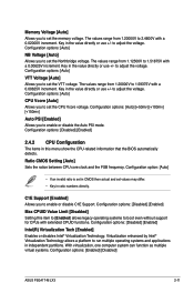
...: [Disabled] [Enabled] Max CPUID Value Limit [Disabled] Setting this menu show the CPU-related information that the BIOS automatically detects. With virtualization, one computer system can function as multiple virtual systems. Configuration options: [Enabled] [Disabled] ASUS P5G41T-M LX3 2-11 Configuration options: [Auto] NB Voltage [Auto] Allows you to set the memory voltage. Key in...
...: [Disabled] [Enabled] Max CPUID Value Limit [Disabled] Setting this menu show the CPU-related information that the BIOS automatically detects. With virtualization, one computer system can function as multiple virtual systems. Configuration options: [Enabled] [Disabled] ASUS P5G41T-M LX3 2-11 Configuration options: [Auto] NB Voltage [Auto] Allows you to set the memory voltage. Key in...


