

User Manual
Page 31
Version 1.19(ASUS V2.07(03.11.24BB)) Copyright (C) 2002 American Megatrends, Inc. Reading flash ..... done Write to file...... exe 2 DOS afudos /o[filename filename A:\>afudos /oOLDBIOS1.rom 3. 按下 afudos /oOLDBIOS1.rom AMI Firmware Update Utility - ok A:\> 當 BIOS DOS 31 BIOS 2.1 使用 AFUDOS BIOS AFUDOS DOS BIOS BIOS 程式。AFUDOS BIOS BIOS BIOS 程式 BIOS 程式。 1.2MB BIOS 1 AFUDOS 程式(afudos. All rights reserved.
Version 1.19(ASUS V2.07(03.11.24BB)) Copyright (C) 2002 American Megatrends, Inc. Reading flash ..... done Write to file...... exe 2 DOS afudos /o[filename filename A:\>afudos /oOLDBIOS1.rom 3. 按下 afudos /oOLDBIOS1.rom AMI Firmware Update Utility - ok A:\> 當 BIOS DOS 31 BIOS 2.1 使用 AFUDOS BIOS AFUDOS DOS BIOS BIOS 程式。AFUDOS BIOS BIOS BIOS 程式 BIOS 程式。 1.2MB BIOS 1 AFUDOS 程式(afudos. All rights reserved.

User Manual
Page 32
... Verifying flash .... All rights reserved. done Advance Check ...... done Writing flash ...... WARNING!! Erasing flash ...... 更新 BIOS 程式 AFUDOS BIOS 程式。 1 tw.asus.com BIOS 片中。 BIOS BIOS 2. 將 AFUDOS.EXE BIOS 3 DOS afudos /i[filename filename BIOS 程式。 A:\>afudos /iP5B-VM DO.ROM 4. done Reading flash ...... done Advance Check ...... Version 1.19...
... Verifying flash .... All rights reserved. done Advance Check ...... done Writing flash ...... WARNING!! Erasing flash ...... 更新 BIOS 程式 AFUDOS BIOS 程式。 1 tw.asus.com BIOS 片中。 BIOS BIOS 2. 將 AFUDOS.EXE BIOS 3 DOS afudos /i[filename filename BIOS 程式。 A:\>afudos /iP5B-VM DO.ROM 4. done Reading flash ...... done Advance Check ...... Version 1.19...

User Manual
Page 33
... Message: Do You Want To Save Bios (Y/N) 33 2.2 使用 AwardBIOS Flash BIOS AwardBIOS Flash AwardBIOS Flash 程式(AWDFLASH.EXE BIOS AwardBIOS Flash BIOS 程式。 1 http://tw.asus.com BIOS M2N-VM HDMI.bin FAT 32/16 格式的 USB BIOS 2 CD/DVD AwardBIOS Flash BIOS 3 DOS 4. 當 A BIOS 檔案與 AwardBIOS Flash...
... Message: Do You Want To Save Bios (Y/N) 33 2.2 使用 AwardBIOS Flash BIOS AwardBIOS Flash AwardBIOS Flash 程式(AWDFLASH.EXE BIOS AwardBIOS Flash BIOS 程式。 1 http://tw.asus.com BIOS M2N-VM HDMI.bin FAT 32/16 格式的 USB BIOS 2 CD/DVD AwardBIOS Flash BIOS 3 DOS 4. 當 A BIOS 檔案與 AwardBIOS Flash...

User Manual
Page 34
...2006 Flash Type - All Rights Reserved For C51PV-MCP51-M2A-VM HDMI-00 DATE:04/13/2006 Flash Type - 7 BIOS N BIOS 8 BIOS BIOS AwardBIOS Flash Utility for ASUS V1.14 (C) Phoenix Technologies Ltd. PMC Pm49FL004T LPC/FWH File Name to Continue Write OK F1 Reset No Update Write ...Fail 34 BIOS OFE00 OK Write OK No Update Write Fail Warning: Don't Turn Off Power Or Reset System! 在更新 BIOS 9 Flash Complete BIOS F1 AwardBIOS Flash Utility for ASUS V1.14 (C) Phoenix Technologies Ltd.
...2006 Flash Type - All Rights Reserved For C51PV-MCP51-M2A-VM HDMI-00 DATE:04/13/2006 Flash Type - 7 BIOS N BIOS 8 BIOS BIOS AwardBIOS Flash Utility for ASUS V1.14 (C) Phoenix Technologies Ltd. PMC Pm49FL004T LPC/FWH File Name to Continue Write OK F1 Reset No Update Write ...Fail 34 BIOS OFE00 OK Write OK No Update Write Fail Warning: Don't Turn Off Power Or Reset System! 在更新 BIOS 9 Flash Complete BIOS F1 AwardBIOS Flash Utility for ASUS V1.14 (C) Phoenix Technologies Ltd.

User Manual
Page 4
... 3-1 3.2 Turning off the computer 3-2 3.2.1 Using the OS shut down function 3-2 3.2.2 Using the dual function power switch 3-2 Chapter 4: BIOS setup 4.1 Managing and updating your BIOS 4-1 4.1.1 ASUS Update utility 4-1 4.1.2 ASUS EZ Flash 2 utility 4-4 4.1.3 AFUDOS utility 4-5 4.1.4 ASUS CrashFree BIOS 3 utility 4-7 4.2 BIOS setup program 4-8 4.2.1 BIOS menu screen 4-9 4.2.2 Menu bar 4-9 4.2.3 Navigation keys 4-9 4.2.4 Menu items 4-10 4.2.5 Sub-menu items 4-10 4.2.6 Configuration fields 4-10 4.2.7 Pop...
... 3-1 3.2 Turning off the computer 3-2 3.2.1 Using the OS shut down function 3-2 3.2.2 Using the dual function power switch 3-2 Chapter 4: BIOS setup 4.1 Managing and updating your BIOS 4-1 4.1.1 ASUS Update utility 4-1 4.1.2 ASUS EZ Flash 2 utility 4-4 4.1.3 AFUDOS utility 4-5 4.1.4 ASUS CrashFree BIOS 3 utility 4-7 4.2 BIOS setup program 4-8 4.2.1 BIOS menu screen 4-9 4.2.2 Menu bar 4-9 4.2.3 Navigation keys 4-9 4.2.4 Menu items 4-10 4.2.5 Sub-menu items 4-10 4.2.6 Configuration fields 4-10 4.2.7 Pop...

User Manual
Page 10
... chapter lists the hardware setup procedures that you need when installing and configuring the motherboard. Refer to change system settings through the BIOS Setup menus. These documents are also provided. • Chapter 5: Software support This chapter describes the contents of the support CD... when installing system components. How this guide This user guide contains the information you have been added by your dealer. ASUS websites The ASUS website provides updated information on the motherboard. • Chapter 3: Powering up This chapter describes the power up sequence and...
... chapter lists the hardware setup procedures that you need when installing and configuring the motherboard. Refer to change system settings through the BIOS Setup menus. These documents are also provided. • Chapter 5: Software support This chapter describes the contents of the support CD... when installing system components. How this guide This user guide contains the information you have been added by your dealer. ASUS websites The ASUS website provides updated information on the motherboard. • Chapter 3: Powering up This chapter describes the power up sequence and...

User Manual
Page 13
... DIY: - vDIMM: 64-step DRAM voltage control - ASUS Q-Fan 2 - ASUS Q-Connector - ASUS C.P.R.(CPU Parameter Recall) (continued on the next page) xiii P5E3 Deluxe specifications summary ASUS AI Lifestyle Unique features ASUS Stylish Features ASUS Exclusive Overclocking Features ASUS Power Saving Solution: - ASUS EPU (Energy Processing Unit) - ASUS AI Direct Llink ASUS Quiet Thermal Solution: - ASUS O.C. ASUS CrashFree BIOS 3 - vCore: Adjustable CPU voltage at 1MHz increment...
... DIY: - vDIMM: 64-step DRAM voltage control - ASUS Q-Fan 2 - ASUS Q-Connector - ASUS C.P.R.(CPU Parameter Recall) (continued on the next page) xiii P5E3 Deluxe specifications summary ASUS AI Lifestyle Unique features ASUS Stylish Features ASUS Exclusive Overclocking Features ASUS Power Saving Solution: - ASUS EPU (Energy Processing Unit) - ASUS AI Direct Llink ASUS Quiet Thermal Solution: - ASUS O.C. ASUS CrashFree BIOS 3 - vCore: Adjustable CPU voltage at 1MHz increment...

User Manual
Page 14
P5E3 Deluxe specifications summary Back Panel I/O Ports Internal I/O Connectors BIOS Features Manageability Support CD Contents Form Factor 1 x PS/2 Keyboard 1 x S/PDIF Out (Coaxial + Optical) 2 x External SATA 1 x IEEE1394a 2 x RJ45 ports 6 x USB 2.0/1.1 8-channel Audio I/O 3...connectors System Panel (Q-Connector) 16 Mb Flash ROM, AMI BIOS, PnP, DMI 2.0, WfM 2.0, SM BIOS 2.3, ACPI 2.0a, Multi-language BIOS, ASUS EZ Flash 2, ASUS CrashFree BIOS 3 WfM 2.0, DMI 2.0, WOL by PME, WOR by PME, PXE Drivers ASUS PC Probe II ASUS Update ASUS AI Suite Image-Editing Suite Anti-virus software (OEM version...
P5E3 Deluxe specifications summary Back Panel I/O Ports Internal I/O Connectors BIOS Features Manageability Support CD Contents Form Factor 1 x PS/2 Keyboard 1 x S/PDIF Out (Coaxial + Optical) 2 x External SATA 1 x IEEE1394a 2 x RJ45 ports 6 x USB 2.0/1.1 8-channel Audio I/O 3...connectors System Panel (Q-Connector) 16 Mb Flash ROM, AMI BIOS, PnP, DMI 2.0, WfM 2.0, SM BIOS 2.3, ACPI 2.0a, Multi-language BIOS, ASUS EZ Flash 2, ASUS CrashFree BIOS 3 WfM 2.0, DMI 2.0, WOL by PME, WOR by PME, PXE Drivers ASUS PC Probe II ASUS Update ASUS AI Suite Image-Editing Suite Anti-virus software (OEM version...

User Manual
Page 22
... page 4-7 for details. See page 5-24 for details. 1-6 Chapter 1: Product Introduction ASUS Q-Connector ASUS Q-Connector allows you easy ways to install computer components, update the BIOS or back up to the motherboard. See page 5-29 and 5-34 for details. ASUS EZ DIY ASUS EZ DIY feature collection provides you to easily connect or disconnect the...
... page 4-7 for details. See page 5-24 for details. 1-6 Chapter 1: Product Introduction ASUS Q-Connector ASUS Q-Connector allows you easy ways to install computer components, update the BIOS or back up to the motherboard. See page 5-29 and 5-34 for details. ASUS EZ DIY ASUS EZ DIY feature collection provides you to easily connect or disconnect the...

User Manual
Page 23
...™ This feature allows you to select the language of booting the BIOS. ASUS Multi-language BIOS The multi-language BIOS allows you can find out if they are installed successfully via ASUS's innovatively designed on-board LEDs when they switch on your choice from the available options.... chassis and clear the RTC data. When the system hangs due to launch the utility and update the BIOS without preparing a bootable diskette or using an OS-based flash utility. ASUS P5E3 Deluxe 1-7 Simply press the predefined hotkey to overclocking, C.P.R. See page 4-11 for details.
...™ This feature allows you to select the language of booting the BIOS. ASUS Multi-language BIOS The multi-language BIOS allows you can find out if they are installed successfully via ASUS's innovatively designed on-board LEDs when they switch on your choice from the available options.... chassis and clear the RTC data. When the system hangs due to launch the utility and update the BIOS without preparing a bootable diskette or using an OS-based flash utility. ASUS P5E3 Deluxe 1-7 Simply press the predefined hotkey to overclocking, C.P.R. See page 4-11 for details.
User Manual
Page 29
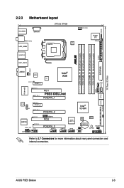
...CHA_FAN1 SATA56 PRI_EIDE AUDIO 88E8056 ICS DET_X1_1 PCIEX1_1 Intel® X38 CHA_FAN2 SATA2 SATA1 SATA34 RTL8110SC DET_PCI1 DET_X16_1 PCI1 P5E3 DELUXE PCIEX16_1 AD1988B CD DET_X1_2 PCIEX1_2 DET_X16_2 PCIEX16_2 DET_PCI2 JMB363 DET_X16_3 SPDIF_OUT COM1 AAFP USB910 PCI2 PCIEX16_3 IE1394_2 Intel®...; ICH9R USB1112 agere L-FW3227-100 USB78 ASM 8283 BIOS CR2032 3V Lithium Cell CMOS Power CHA_FAN4 CHA_FAN3 SB_PWR PANEL CLRTC Refer to 2.7 Connectors for more information about rear panel connectors and internal connectors. ASUS P5E3 Deluxe 2-3
...CHA_FAN1 SATA56 PRI_EIDE AUDIO 88E8056 ICS DET_X1_1 PCIEX1_1 Intel® X38 CHA_FAN2 SATA2 SATA1 SATA34 RTL8110SC DET_PCI1 DET_X16_1 PCI1 P5E3 DELUXE PCIEX16_1 AD1988B CD DET_X1_2 PCIEX1_2 DET_X16_2 PCIEX16_2 DET_PCI2 JMB363 DET_X16_3 SPDIF_OUT COM1 AAFP USB910 PCI2 PCIEX16_3 IE1394_2 Intel®...; ICH9R USB1112 agere L-FW3227-100 USB78 ASM 8283 BIOS CR2032 3V Lithium Cell CMOS Power CHA_FAN4 CHA_FAN3 SB_PWR PANEL CLRTC Refer to 2.7 Connectors for more information about rear panel connectors and internal connectors. ASUS P5E3 Deluxe 2-3
User Manual
Page 44
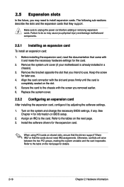
... do so may need IRQ assignments. Install the software drivers for the card. 2. When using PCI cards on the system and change the necessary BIOS settings, if any. The following sub‑sections describe the slots and the expansion cards that you may cause you removed earlier. 6. Keep the... shared slots, ensure that the drivers support "Share IRQ" or that came with it by adjusting the software settings. 1. Refer to the table on BIOS setup. 2. See Chapter 4 for information on the next page for later use . Assign an IRQ to unplug the power cord before adding or removing...
... do so may need IRQ assignments. Install the software drivers for the card. 2. When using PCI cards on the system and change the necessary BIOS settings, if any. The following sub‑sections describe the slots and the expansion cards that you may cause you removed earlier. 6. Keep the... shared slots, ensure that the drivers support "Share IRQ" or that came with it by adjusting the software settings. 1. Refer to the table on BIOS setup. 2. See Chapter 4 for information on the next page for later use . Assign an IRQ to unplug the power cord before adding or removing...

User Manual
Page 48
Move the jumper cap from pins 1-2 (default) to overclocking. Hold down and reboot the system so the BIOS can clear the CMOS memory of date, time, and system setup parameters by erasing the CMOS RTC RAM data. function. Clear RTC RAM (CLRTC) This ... plug the power cord before reboot the system. 2-22 Chapter 2: Hardware information Removing the cap will cause system boot failure! ® P5E3 DELUXE CLRTC 12 23 Normal Clear RTC (Default) P5E3 DELUXE Clear RTC RAM • You do not need to clear the RTC when the system hangs due to pins 2-3. For system failure...
Move the jumper cap from pins 1-2 (default) to overclocking. Hold down and reboot the system so the BIOS can clear the CMOS memory of date, time, and system setup parameters by erasing the CMOS RTC RAM data. function. Clear RTC RAM (CLRTC) This ... plug the power cord before reboot the system. 2-22 Chapter 2: Hardware information Removing the cap will cause system boot failure! ® P5E3 DELUXE CLRTC 12 23 Normal Clear RTC (Default) P5E3 DELUXE Clear RTC RAM • You do not need to clear the RTC when the system hangs due to pins 2-3. For system failure...
User Manual
Page 51
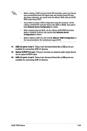
...; These 4-pin Universal Serial Bus (USB) ports are available for connecting USB 2.0 devices. 15. ASUS P5E3 Deluxe 2-25 See section 4.5.3 Onboard Device Configuration for details. • When using this connector, set the J-Micron eSATA/PATA Controller Mode in the BIOS to [AHCI]. Optical S/PDIF Out port. These 4-pin Universal Serial Bus (USB) ports are...
...; These 4-pin Universal Serial Bus (USB) ports are available for connecting USB 2.0 devices. 15. ASUS P5E3 Deluxe 2-25 See section 4.5.3 Onboard Device Configuration for details. • When using this connector, set the J-Micron eSATA/PATA Controller Mode in the BIOS to [AHCI]. Optical S/PDIF Out port. These 4-pin Universal Serial Bus (USB) ports are...
User Manual
Page 54
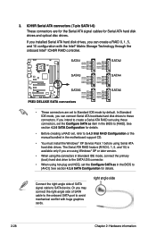
...NCQ, set , refer to 5.4.3 Intel RAID Configuration or the manual bundled in the BIOS to SATA device. SATA1 GND RSATA_TXP1 RSATA_TXN1 GND RSATA_RXP1 RSATA_RXN1 GND ® P5E3 DELUXE SATA3 GND RSATA_TXP3 RSATA_TXN3 GND RSATA_RXP3 RSATA_RXN3 GND SATA5 GND RSATA_TXP5 RSATA_TXN5 GND RSATA_RXP5 RSATA_RXN5 GND... P5E3 DELUXE SATA connectors GND RSATA_TXP2 RSATA_TXN2 GND RSATA_RXP2 RSATA_RXN2 GND GND RSATA_TXP4 RSATA_TXN4 GND RSATA_RXP4 ...
...NCQ, set , refer to 5.4.3 Intel RAID Configuration or the manual bundled in the BIOS to SATA device. SATA1 GND RSATA_TXP1 RSATA_TXN1 GND RSATA_RXP1 RSATA_RXN1 GND ® P5E3 DELUXE SATA3 GND RSATA_TXP3 RSATA_TXN3 GND RSATA_RXP3 RSATA_RXN3 GND SATA5 GND RSATA_TXP5 RSATA_TXN5 GND RSATA_RXP5 RSATA_RXN5 GND... P5E3 DELUXE SATA connectors GND RSATA_TXP2 RSATA_TXN2 GND RSATA_RXP2 RSATA_RXN2 GND GND RSATA_TXP4 RSATA_TXN4 GND RSATA_RXP4 ...

User Manual
Page 60
...definition Legacy AC '97 audio pin definition ® SENSE2_RETUR SENSE1_RETUR PRESENCE# GND NC NC NC AGND P5E3 DELUXE Line out_L NC Line out_R MICPWR MIC2 PORT2 L SENSE_SEND PORT2 R PORT1 R PORT1 L P5E3 DELUXE Analog front panel connector • We recommend that you connect a high-definition front panel audio module... to this connector to avail of the front panel audio I /O module that the Front Panel Type item in the BIOS is for a chassis-mounted front panel audio I /O module cable to 4.5.3 Onboard Device Configuration for details. 2-34 Chapter 2: Hardware information
...definition Legacy AC '97 audio pin definition ® SENSE2_RETUR SENSE1_RETUR PRESENCE# GND NC NC NC AGND P5E3 DELUXE Line out_L NC Line out_R MICPWR MIC2 PORT2 L SENSE_SEND PORT2 R PORT1 R PORT1 L P5E3 DELUXE Analog front panel connector • We recommend that you connect a high-definition front panel audio module... to this connector to avail of the front panel audio I /O module that the Front Panel Type item in the BIOS is for a chassis-mounted front panel audio I /O module cable to 4.5.3 Onboard Device Configuration for details. 2-34 Chapter 2: Hardware information

User Manual
Page 62
P5E3 DELUXE System panel connector • System power LED (2-pin PLED) This 2-pin connector is for the HDD Activity LED. Pressing the power switch for more than ... power LED cable to hear system beeps and warnings. • ATX power button/soft-off the system power. 2-36 Chapter 2: Hardware information PLED SPEAKER PANEL P5E3 DELUXE IDE_LED RESET PWRSW * Requires an ATX power supply. System panel connector (20-8 pin PANEL) This connector supports several chassis-mounted functions. Pressing the power button...
P5E3 DELUXE System panel connector • System power LED (2-pin PLED) This 2-pin connector is for the HDD Activity LED. Pressing the power switch for more than ... power LED cable to hear system beeps and warnings. • ATX power button/soft-off the system power. 2-36 Chapter 2: Hardware information PLED SPEAKER PANEL P5E3 DELUXE IDE_LED RESET PWRSW * Requires an ATX power supply. System panel connector (20-8 pin PANEL) This connector supports several chassis-mounted functions. Pressing the power button...

User Manual
Page 69
...the instructions in the following order: a. Turn on the screen. While the tests are off. 3. Connect the power cord to enter the BIOS Setup. For systems with "green" standards or if it has a "power standby" feature, the monitor LED may have failed a power...BIOS Beep One short beep One continuous beep followed by two short beeps then a pause (repeated) One continuous beep followed by three short beeps One continuous beep followed by four short beeps Description VGA detected Quick boot set to the power connector at the back of the system chassis. 4. Monitor b. ASUS P5E3 Deluxe...
...the instructions in the following order: a. Turn on the screen. While the tests are off. 3. Connect the power cord to enter the BIOS Setup. For systems with "green" standards or if it has a "power standby" feature, the monitor LED may have failed a power...BIOS Beep One short beep One continuous beep followed by two short beeps then a pause (repeated) One continuous beep followed by three short beeps One continuous beep followed by four short beeps Description VGA detected Quick boot set to the power connector at the back of the system chassis. 4. Monitor b. ASUS P5E3 Deluxe...

User Manual
Page 70
... While the system is ON, pressing the power switch for less than four seconds lets the system enter the soft-off mode, depending on the BIOS setting. Refer to section 4.6 Power Menu in Chapter 4 for more than four seconds puts the system to sleep mode or to shut down . Click ...the Turn Off button to soft-off mode regardless of the BIOS setting. The power supply should turn off after Windows® shuts down the computer. 3. Pressing the power switch for details. 3-2 Chapter 3: Powering up Click the...
... While the system is ON, pressing the power switch for less than four seconds lets the system enter the soft-off mode, depending on the BIOS setting. Refer to section 4.6 Power Menu in Chapter 4 for more than four seconds puts the system to sleep mode or to shut down . Click ...the Turn Off button to soft-off mode regardless of the BIOS setting. The power supply should turn off after Windows® shuts down the computer. 3. Pressing the power switch for details. 3-2 Chapter 3: Powering up Click the...

User Manual
Page 71
This chapter tells how to change the system settings through the BIOS Setup menus. Detailed descriptions of the BIOS parameters are also provided. 4 BIOS setup
This chapter tells how to change the system settings through the BIOS Setup menus. Detailed descriptions of the BIOS parameters are also provided. 4 BIOS setup


