
P5A User Manual
Page 8
....) (See section V) • USB, PS/2 Mouse, IrDA Connector: Supports an optional cable and bracket set . 8 ASUS P5A User's Manual A second IrDA connector is available for virtually automatic setup. • PC100 Memory Support: Equipped with EPP and ECP capabilities. ...FEATURES ASUS P5A Motherboard • ALi AGPset: ALi® (Acer Laboratories Inc.) Aladdin V AGPset with support for a 100MHz Front Side Bus (FSB), Accelerated Graphics Port (AGP), and all current Socket 7 processors. • Multi-Processor/Multi-Speed Support...
....) (See section V) • USB, PS/2 Mouse, IrDA Connector: Supports an optional cable and bracket set . 8 ASUS P5A User's Manual A second IrDA connector is available for virtually automatic setup. • PC100 Memory Support: Equipped with EPP and ECP capabilities. ...FEATURES ASUS P5A Motherboard • ALi AGPset: ALi® (Acer Laboratories Inc.) Aladdin V AGPset with support for a 100MHz Front Side Bus (FSB), Accelerated Graphics Port (AGP), and all current Socket 7 processors. • Multi-Processor/Multi-Speed Support...

P5A User Manual
Page 11
FEATURES Parts of the ASUS P5A Motherboard PS/2 Mouse (top) and Keyboard USB Port ATX Power CPU ZIF ALi Aladdin V Socket 7 AGPset 3 DIMM Sockets Serial and Parallel Connectors 512KB/1MB Pipelined Burst L2 Cache Game/MIDI Port (optional) Accelerated Graphics Port ESS Audio (optional) 5 PCI Slots Health Monitoring Chip (optional) 2 ISA Slots ASUS P5A User's Manual 11 FEA TURES Motherboard Parts II. II.
FEATURES Parts of the ASUS P5A Motherboard PS/2 Mouse (top) and Keyboard USB Port ATX Power CPU ZIF ALi Aladdin V Socket 7 AGPset 3 DIMM Sockets Serial and Parallel Connectors 512KB/1MB Pipelined Burst L2 Cache Game/MIDI Port (optional) Accelerated Graphics Port ESS Audio (optional) 5 PCI Slots Health Monitoring Chip (optional) 2 ISA Slots ASUS P5A User's Manual 11 FEA TURES Motherboard Parts II. II.
P5A User Manual
Page 12
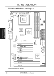
... Cell ALi M1543C Chipset (IDE Controller) CLRTC IR + IDELED Panel Connections 12 ASUS P5A User's Manual INSTALLATION ASUS P5A Motherboard Layout PS2 Top: Mouse Bottom: Keyboard KBMS KBPWR Board Power Input for ATX Power Supply USB Top: USB 1 Bottom: USB 2 PWR_FAN CPU ZIF Socket 7 CPU_FAN CPU Thermal Sensor (Hardware Monitor) VID0 VID1 VID2 VID3 CPU...
... Cell ALi M1543C Chipset (IDE Controller) CLRTC IR + IDELED Panel Connections 12 ASUS P5A User's Manual INSTALLATION ASUS P5A Motherboard Layout PS2 Top: Mouse Bottom: Keyboard KBMS KBPWR Board Power Input for ATX Power Supply USB Top: USB 1 Bottom: USB 2 PWR_FAN CPU ZIF Socket 7 CPU_FAN CPU Thermal Sensor (Hardware Monitor) VID0 VID1 VID2 VID3 CPU...
P5A User Manual
Page 13
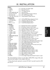
ASUS P5A User's Manual 13 III. INST ALLATION Contents III. INSTALLATION Jumpers 1) CLRTC p. 14 Real Time Clock (RTC) RAM 2) KBPWR p. 15 Keyboard Power Up 3) VIO1 p. 15 +3V ... p. 16 CPU to BUS Frequency Ratio 7) VID0, VID1, VID2, VID3 p. 18 Voltage Regulator Output Selection Expansion Slots 1) DIMM Sockets 2) CPU ZIF Socket 7 3) SLOT 1, 2 4) PCI 1, 2, 3,4,5 p. 19 168-Pin DIMM Memory Expansion Sockets p. 21 Central Processing Unit (CPU) Socket p. 23 16-bit ISA Bus Expansion Slots* p. 23 32-bit PCI Bus Expansion Slots** Connectors 1) PS2KBMS p. 25...
ASUS P5A User's Manual 13 III. INST ALLATION Contents III. INSTALLATION Jumpers 1) CLRTC p. 14 Real Time Clock (RTC) RAM 2) KBPWR p. 15 Keyboard Power Up 3) VIO1 p. 15 +3V ... p. 16 CPU to BUS Frequency Ratio 7) VID0, VID1, VID2, VID3 p. 18 Voltage Regulator Output Selection Expansion Slots 1) DIMM Sockets 2) CPU ZIF Socket 7 3) SLOT 1, 2 4) PCI 1, 2, 3,4,5 p. 19 168-Pin DIMM Memory Expansion Sockets p. 21 Central Processing Unit (CPU) Socket p. 23 16-bit ISA Bus Expansion Slots* p. 23 32-bit PCI Bus Expansion Slots** Connectors 1) PS2KBMS p. 25...

P5A User Manual
Page 19
...come in 32, 64, 128, 256MB. patible with memory chips) of the DIMM takes up one row on the motherboard. ASUS P5A User's Manual 19 Sockets are available for 3.3Volt (power level) unbuffered Synchronous Dynamic Random Access Memory (SDRAM) of either available as follows: DIMM Location... 8 chips/side + 1 ECC chip) and make using bus speeds ≥95MHz possible, SDRAMs used because of choice for system stability. • ASUS motherboards support SPD (Serial Presence Detect) DIMMs. This is recommended through "Chipset Features Setup" in 16, 32, 64,128MB; stability. • SDRAM...
...come in 32, 64, 128, 256MB. patible with memory chips) of the DIMM takes up one row on the motherboard. ASUS P5A User's Manual 19 Sockets are available for 3.3Volt (power level) unbuffered Synchronous Dynamic Random Access Memory (SDRAM) of either available as follows: DIMM Location... 8 chips/side + 1 ECC chip) and make using bus speeds ≥95MHz possible, SDRAMs used because of choice for system stability. • ASUS motherboards support SPD (Serial Presence Detect) DIMMs. This is recommended through "Chipset Features Setup" in 16, 32, 64,128MB; stability. • SDRAM...

P5A User Manual
Page 20
... slot on either side of pins are different on the motherboard. INST ALLATION System Memory 88 Pins 60 Pins 20 Pins Lock P5A 168 Pin DIMM Memory Sockets The DIMMs must tell your retailer the correct DIMM type before purchasing. III. SDRAM DIMMs have a higher pin density. You ...5.0V Reserved 3.3V The notches on the DIMM will only fit in the orientation as shown. This motherboard supports four clock signals. 20 ASUS P5A User's Manual DRAM SIMM modules have the same pin contacts on each side and therefore have different pin contacts on both sides. INSTALLATION DIMM...
... slot on either side of pins are different on the motherboard. INST ALLATION System Memory 88 Pins 60 Pins 20 Pins Lock P5A 168 Pin DIMM Memory Sockets The DIMMs must tell your retailer the correct DIMM type before purchasing. III. SDRAM DIMMs have a higher pin density. You ...5.0V Reserved 3.3V The notches on the DIMM will only fit in the orientation as shown. This motherboard supports four clock signals. 20 ASUS P5A User's Manual DRAM SIMM modules have the same pin contacts on each side and therefore have different pin contacts on both sides. INSTALLATION DIMM...

P5A User Manual
Page 21
...occur to BUS Frequency Ratio" and jumpers for reference only; Blank 1 Lever Lock R P5A ZIF Socket 7 ASUS P5A User's Manual 21 Use the notched corner of pin holes and a "1" printed on the fan and close the socket's lever. The picture is backwards compatible with the correct orientation as your guide. you ... turn on the CPU, the CPU can overheat and cause damage to both the CPU and the motherboard. WARNING! Insert the CPU with ZIF Socket 5 processors. Because the CPU has a corner pin for three of the lever. Once completely inserted, hold down on the motherboard next to ...
...occur to BUS Frequency Ratio" and jumpers for reference only; Blank 1 Lever Lock R P5A ZIF Socket 7 ASUS P5A User's Manual 21 Use the notched corner of pin holes and a "1" printed on the fan and close the socket's lever. The picture is backwards compatible with the correct orientation as your guide. you ... turn on the CPU, the CPU can overheat and cause damage to both the CPU and the motherboard. WARNING! Insert the CPU with ZIF Socket 5 processors. Because the CPU has a corner pin for three of the lever. Once completely inserted, hold down on the motherboard next to ...

P5A User Manual
Page 27
... In allows tape players or other audio sources to this connector for inputing voice. Universal Serial BUS Ports 1 & 2 (Two 4-pin Female Sockets) Two USB ports are available for playing or editing audio. Joystick/Midi Connector (15-pin Female) (with optional onboard audio) Line Out can...or played through the Line Out. Line Out Line In Mic 1/8" Stereo Audio Connectors 7. USB 1 Universal Serial Bus (USB) 2 ASUS P5A User's Manual 27 INST ALLATION Connectors III. Connect Midi devices for connecting USB devices. III. Mic allows microphones to headphones or preferably powered ...
... In allows tape players or other audio sources to this connector for inputing voice. Universal Serial BUS Ports 1 & 2 (Two 4-pin Female Sockets) Two USB ports are available for playing or editing audio. Joystick/Midi Connector (15-pin Female) (with optional onboard audio) Line Out can...or played through the Line Out. Line Out Line In Mic 1/8" Stereo Audio Connectors 7. USB 1 Universal Serial Bus (USB) 2 ASUS P5A User's Manual 27 INST ALLATION Connectors III. Connect Midi devices for connecting USB devices. III. Mic allows microphones to headphones or preferably powered ...

P5A User Manual
Page 68
...including Windows. A byte is a logical device name used to communicate with devices such as 3D video, 3D sound, video conference. 68 ASUS P5A User's Manual IDE (Integrated Drive Electronics) IDE devices integrate the drive control circuitry directly on a technique called "Processor," actually functions as ...data stored in the case for allocating system resources such as the "brain" of eight contiguous bits. The MMX instructions are socket 370 (for Pentium Celeron-PPGA), socket 7 (for Pentium, AMD, Cyrix, IBM), slot 1 (for Pentium II and III), and slot 2 (for the computer...
...including Windows. A byte is a logical device name used to communicate with devices such as 3D video, 3D sound, video conference. 68 ASUS P5A User's Manual IDE (Integrated Drive Electronics) IDE devices integrate the drive control circuitry directly on a technique called "Processor," actually functions as ...data stored in the case for allocating system resources such as the "brain" of eight contiguous bits. The MMX instructions are socket 370 (for Pentium Celeron-PPGA), socket 7 (for Pentium, AMD, Cyrix, IBM), slot 1 (for Pentium II and III), and slot 2 (for the computer...


