
P5A-B User Manual
Page 2
Manual updates are both printed on the following page. Product Name: ASUS P5A-B Manual Revision: 1.07 E381 Release Date: April 1999 2 ASUS P5A-B User's Manual or (2) the serial number of the product is authorized in the manual revision number. ...without the express written permission of ASUSTeK COMPUTER INC. ("ASUS"). For previous or updated manuals, BIOS, drivers, or product release information, contact ASUS at http://www.asus.com.tw or through any means, except documentation kept by ASUS; ASUS ASSUMES NO RESPONSIBILITY OR LIABILITY FOR ANY ERRORS OR INACCURACIES...
Manual updates are both printed on the following page. Product Name: ASUS P5A-B Manual Revision: 1.07 E381 Release Date: April 1999 2 ASUS P5A-B User's Manual or (2) the serial number of the product is authorized in the manual revision number. ...without the express written permission of ASUSTeK COMPUTER INC. ("ASUS"). For previous or updated manuals, BIOS, drivers, or product release information, contact ASUS at http://www.asus.com.tw or through any means, except documentation kept by ASUS; ASUS ASSUMES NO RESPONSIBILITY OR LIABILITY FOR ANY ERRORS OR INACCURACIES...

P5A-B User Manual
Page 4
... of PNP and PCI Setup 52 4 ASUS P5A-B User's Manual INTRODUCTION 7 How this Manual is Organized 7 Item Checklist 7 II. BIOS SOFTWARE 36 Flash Memory Writer Utility 36 Main Menu 36 Managing and Updating Your Motherboard's BIOS 38 6. Jumpers 14 Jumper Settings 15 Compatible Cyrix CPU Identification 18 2. BIOS Setup 39 Load Defaults 40 Standard CMOS...
... of PNP and PCI Setup 52 4 ASUS P5A-B User's Manual INTRODUCTION 7 How this Manual is Organized 7 Item Checklist 7 II. BIOS SOFTWARE 36 Flash Memory Writer Utility 36 Main Menu 36 Managing and Updating Your Motherboard's BIOS 38 6. Jumpers 14 Jumper Settings 15 Compatible Cyrix CPU Identification 18 2. BIOS Setup 39 Load Defaults 40 Standard CMOS...

P5A-B User Manual
Page 5
... Interface (DMI 60 Introducing the ASUS DMI Configuration Utility 60 Starting the ASUS DMI Configuration Utility 60 Using the ASUS DMI Configuration Utility 61 VI. ASUS CIDB 63 The ASUS CIDB Chassis Sensor 63 Using the ASUS CIDB 63 Setting up the ASUS CIDB 64 ASUS CIDB Additional Considerations 64 VII. CONTENTS Load BIOS Defaults 54 Load Setup Defaults...
... Interface (DMI 60 Introducing the ASUS DMI Configuration Utility 60 Starting the ASUS DMI Configuration Utility 60 Using the ASUS DMI Configuration Utility 61 VI. ASUS CIDB 63 The ASUS CIDB Chassis Sensor 63 Using the ASUS CIDB 63 Setting up the ASUS CIDB 64 ASUS CIDB Additional Considerations 64 VII. CONTENTS Load BIOS Defaults 54 Load Setup Defaults...

P5A-B User Manual
Page 7
...BIOS Software Instructions on setting up the motherboard IV. ASUS L101 Card Installation of the ASUS LAN card (optional) APPENDIX Glossary of Terms Item Checklist Check that your retailer. (1) ASUS...3.5" floppy disk drives (1) Bag of the ASUS CIDB Chassis Sensor (optional) VII. If ...BIOS software V. Introduction Manual information and checklist II. Installation Instructions on the included support software VI. ASUS... CIDB Installation of spare jumpers (1) CD disc with support drivers and utilities (1) User's Manual Audio Bracket (only available with ISA audio option) ASUS...
...BIOS Software Instructions on setting up the motherboard IV. ASUS L101 Card Installation of the ASUS LAN card (optional) APPENDIX Glossary of Terms Item Checklist Check that your retailer. (1) ASUS...3.5" floppy disk drives (1) Bag of the ASUS CIDB Chassis Sensor (optional) VII. If ...BIOS software V. Introduction Manual information and checklist II. Installation Instructions on the included support software VI. ASUS... CIDB Installation of spare jumpers (1) CD disc with support drivers and utilities (1) User's Manual Audio Bracket (only available with ISA audio option) ASUS...

P5A-B User Manual
Page 8
...(Requires DMI-enabled components.) (See section V) • USB, PS/2 Mouse, IrDA Connector: Supports an optional cable and bracket set . 8 ASUS P5A-B User's Manual These new SDRAMs are necessary to meet the 95MHz/100MHz bus speed requirement. • AGP Slot: Supports AGP cards for high ... standard individual infrared cable set to mount the connectors to 768MB. FEATURES ASUS P5A-B Motherboard • ALi AGPset: ALi® (Acer Laboratories Inc.) Aladdin V AGPset with EPP and ECP capabilities. II. BIOS supports IDE CD-ROM or SCSI device boot-up to an unused expansion...
...(Requires DMI-enabled components.) (See section V) • USB, PS/2 Mouse, IrDA Connector: Supports an optional cable and bracket set . 8 ASUS P5A-B User's Manual These new SDRAMs are necessary to meet the 95MHz/100MHz bus speed requirement. • AGP Slot: Supports AGP cards for high ... standard individual infrared cable set to mount the connectors to 768MB. FEATURES ASUS P5A-B Motherboard • ALi AGPset: ALi® (Acer Laboratories Inc.) Aladdin V AGPset with EPP and ECP capabilities. II. BIOS supports IDE CD-ROM or SCSI device boot-up to an unused expansion...
P5A-B User Manual
Page 9
...Master IDE, which can be used. • PC'98 Compliant: Both the BIOS and hardware levels of all is that supports ACPI, such as Windows 98, must be ready around the clock, yet satisfy all ASUS Smart Series motherboards. The new PC'98 requirements for systems and components are ... To prevent system overheat and system damage, there is operating at a safe heat level to 33MB/sec. The best of the ASUS Smart Series motherboards meet PC'98 compliancy. ASUS P5A-B User's Manual 9 FEA TURES Smart Series II. II. With these features implemented in the OS, PCs can handle data transfer...
...Master IDE, which can be used. • PC'98 Compliant: Both the BIOS and hardware levels of all is that supports ACPI, such as Windows 98, must be ready around the clock, yet satisfy all ASUS Smart Series motherboards. The new PC'98 requirements for systems and components are ... To prevent system overheat and system damage, there is operating at a safe heat level to 33MB/sec. The best of the ASUS Smart Series motherboards meet PC'98 compliancy. ASUS P5A-B User's Manual 9 FEA TURES Smart Series II. II. With these features implemented in the OS, PCs can handle data transfer...
P5A-B User Manual
Page 12
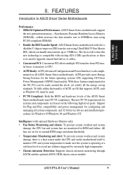
III. INSTALLATION ASUS P5A-B Motherboard Layout AT Keyboard Connector KB USB, PS/2 Mouse, IrDA COM 1 COM 2 Parallel Port Row 5 4 3 2 1 0 VIO1 AT Power Connector VIO0 FS3 FS2 PWR_FAN FS1 FS0 ... Slot 2 PCI Slot 3 ISA Slot 1 CR2032 3V Lithium Cell Chassis Intrusion Alarm Lead AUX SMBus Connector CD1 CPU_FAN CLRTC Audio Connectors 1Mbit Flash EEPROM (Programmable BIOS) C-Media 3D Positional Sound Chip (optional) VID3 VID2 VID1 VID0 CHA_FAN SPDI SPDO TTL ISA Slot 2 IDELED IR + Panel Connectors III. INST ALLATION Motherboard Layout...
III. INSTALLATION ASUS P5A-B Motherboard Layout AT Keyboard Connector KB USB, PS/2 Mouse, IrDA COM 1 COM 2 Parallel Port Row 5 4 3 2 1 0 VIO1 AT Power Connector VIO0 FS3 FS2 PWR_FAN FS1 FS0 ... Slot 2 PCI Slot 3 ISA Slot 1 CR2032 3V Lithium Cell Chassis Intrusion Alarm Lead AUX SMBus Connector CD1 CPU_FAN CLRTC Audio Connectors 1Mbit Flash EEPROM (Programmable BIOS) C-Media 3D Positional Sound Chip (optional) VID3 VID2 VID1 VID0 CHA_FAN SPDI SPDO TTL ISA Slot 2 IDELED IR + Panel Connectors III. INST ALLATION Motherboard Layout...
P5A-B User Manual
Page 14
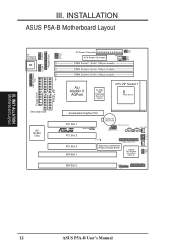
... the Central Processing Unit (CPU) 4. Connect Ribbon Cables, Cabinet Wires, and Power Supply 6. Set Jumpers on your computer, you work on the Motherboard 2. Setup the BIOS Software 1. III. III. Place components on a grounded antistatic pad or on the bag that came with the component whenever the components are separated from static...
... the Central Processing Unit (CPU) 4. Connect Ribbon Cables, Cabinet Wires, and Power Supply 6. Set Jumpers on your computer, you work on the Motherboard 2. Setup the BIOS Software 1. III. III. Place components on a grounded antistatic pad or on the bag that came with the component whenever the components are separated from static...

P5A-B User Manual
Page 15
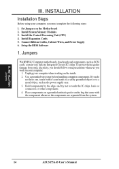
... points using a small metalic object, (3) Turn on your computer components' life. VIO0 VIO1 VIO0 VIO1 VIO0 VIO1 VIO0 VIO1 III. ASUS P5A-B User's Manual 15 Real Time Clock (RTC) RAM (CLRTC) The CMOS RAM is powered by the onboard button cell battery...preferences. R 1 2 3 3.5Volts 3.6Volts 3.8Volts (DEFAULT) 4.0Volts P5A-B Voltage Input/Output Selection WARNING! Using a higher voltage may help when overclocking but may result in the shortening of your computer, (4) Hold down during bootup and enter BIOS setup to Clear CMOS 2. Voltage Input/Output Selection (VIO) This jumper...
... points using a small metalic object, (3) Turn on your computer components' life. VIO0 VIO1 VIO0 VIO1 VIO0 VIO1 VIO0 VIO1 III. ASUS P5A-B User's Manual 15 Real Time Clock (RTC) RAM (CLRTC) The CMOS RAM is powered by the onboard button cell battery...preferences. R 1 2 3 3.5Volts 3.6Volts 3.8Volts (DEFAULT) 4.0Volts P5A-B Voltage Input/Output Selection WARNING! Using a higher voltage may help when overclocking but may result in the shortening of your computer, (4) Hold down during bootup and enter BIOS setup to Clear CMOS 2. Voltage Input/Output Selection (VIO) This jumper...
P5A-B User Manual
Page 19
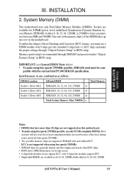
... 64, 128, 256MB. To utilize the chipset's Error Checking and Correction (ECC) feature, you must be com- Install memory in BIOS setup. ASUS P5A-B User's Manual 19 INST ALLATION System Memory Notes • DIMMs that have higher pin density than 18 chips are not supported on this...use a DIMM module with the current Intel PC100 SDRAM specification. Sockets are generally thinner and have more than EDO chips. • BIOS shows SDRAM memory on the motherboard. IMPORTANT (see General DIMM Notes below) • To make the proper settings through SDRAM Configuration under...
... 64, 128, 256MB. To utilize the chipset's Error Checking and Correction (ECC) feature, you must be com- Install memory in BIOS setup. ASUS P5A-B User's Manual 19 INST ALLATION System Memory Notes • DIMMs that have higher pin density than 18 chips are not supported on this...use a DIMM module with the current Intel PC100 SDRAM specification. Sockets are generally thinner and have more than EDO chips. • BIOS shows SDRAM memory on the motherboard. IMPORTANT (see General DIMM Notes below) • To make the proper settings through SDRAM Configuration under...

P5A-B User Manual
Page 23
... of them are available to as "IRQ xx Used By ISA: Yes" in the Windows directory to use IRQs. ASUS P5A-B User's Manual 23 Secure the card on the ISA bus. Setup the BIOS if necessary (such as "Legacy" ISA cards, requires that you configure the card's jumpers manually and then install it...
... of them are available to as "IRQ xx Used By ISA: Yes" in the Windows directory to use IRQs. ASUS P5A-B User's Manual 23 Secure the card on the ISA bus. Setup the BIOS if necessary (such as "Legacy" ISA cards, requires that you configure the card's jumpers manually and then install it...

P5A-B User Manual
Page 24
... the jumpers on this motherboard are assigned automatically from those used by Legacy and PNP ISA cards. P5A-B Accelerated Graphics Port (AGP) 24 ASUS P5A-B User's Manual In the PCI bus design, the BIOS automatically assigns an IRQ to reserve). IMPORTANT: To avoid conflicts, reserve the necessary IRQs and DMAs ...By ISA and DMA x Used By ISA for legacy ISA cards (under PNP AND PCI SETUP of the BIOS Setup utility. For PNP cards, IRQs are handled the same way as an ASUS 3D Hardware Accelerator. NOTE: You must not use a DMA (Direct Memory Access) channel. Since all the...
... the jumpers on this motherboard are assigned automatically from those used by Legacy and PNP ISA cards. P5A-B Accelerated Graphics Port (AGP) 24 ASUS P5A-B User's Manual In the PCI bus design, the BIOS automatically assigns an IRQ to reserve). IMPORTANT: To avoid conflicts, reserve the necessary IRQs and DMAs ...By ISA and DMA x Used By ISA for legacy ISA cards (under PNP AND PCI SETUP of the BIOS Setup utility. For PNP cards, IRQs are handled the same way as an ASUS 3D Hardware Accelerator. NOTE: You must not use a DMA (Direct Memory Access) channel. Since all the...

P5A-B User Manual
Page 26
... open slot. COM 1 Pin 1 COM 2 Pin 1 For these connectors and mount the bracket to a free expansion slot opening . P5A-B Onboard Serial Port Connectors 26 ASUS P5A-B User's Manual A PS/2 mouse connector is included for the USB/ Mouse/IR onboard connector if the optional USB/MIR connector is removed...available the parallel port and choose the IRQ through the Onboard Serial Port in Chipset Features of the BIOS SOFTWARE. (Pin 26 is removed to prevent inserting in Chipset Features of the BIOS SOFTWARE. (Pin 10 is not used. Parallel Connector (PARALLEL, 26-1 pin block) This connector ...
... open slot. COM 1 Pin 1 COM 2 Pin 1 For these connectors and mount the bracket to a free expansion slot opening . P5A-B Onboard Serial Port Connectors 26 ASUS P5A-B User's Manual A PS/2 mouse connector is included for the USB/ Mouse/IR onboard connector if the optional USB/MIR connector is removed...available the parallel port and choose the IRQ through the Onboard Serial Port in Chipset Features of the BIOS SOFTWARE. (Pin 26 is removed to prevent inserting in Chipset Features of the BIOS SOFTWARE. (Pin 10 is not used. Parallel Connector (PARALLEL, 26-1 pin block) This connector ...

P5A-B User Manual
Page 28
... 40-1 pin block) These connectors support the provided IDE hard disk ribbon cable. Refer to the documentation of the BIOS SOFTWARE) (Pin 20 is removed to Pin 1 P5A-B IDE Connectors TIP: You may install one ribbon cable on the primary IDE connector and another on a SCSI drive... and select the boot disk through BIOS Features Setup. 8. IDELED P5A-B IDE Activity LED 28 ASUS P5A-B User's Manual INSTALLATION 7. BIOS now supports SCSI device or IDE CD-ROM bootup (see HDD Sequence SCSI/IDE First & Boot Sequence ...
... 40-1 pin block) These connectors support the provided IDE hard disk ribbon cable. Refer to the documentation of the BIOS SOFTWARE) (Pin 20 is removed to Pin 1 P5A-B IDE Connectors TIP: You may install one ribbon cable on the primary IDE connector and another on a SCSI drive... and select the boot disk through BIOS Features Setup. 8. IDELED P5A-B IDE Activity LED 28 ASUS P5A-B User's Manual INSTALLATION 7. BIOS now supports SCSI device or IDE CD-ROM bootup (see HDD Sequence SCSI/IDE First & Boot Sequence ...

P5A-B User Manual
Page 30
...BIOS Features Setup and USB Function in Chipset Features Setup to purchase an external connector set connects to the 18-pin block and mounts to the motherboard. See Second IrDA... You must connect an optional Infrared module to an open slot on your computer's chassis. P5A-B Infrared Module Connector 30 ASUS P5A..., 18-1 pin block) If you must also configure the setting through UART2 Use Infrared in PnP and PCI Setup of the BIOS SOFTWARE. IrDA-Compliant Infrared Module Connector (IR, 5-pin block) This connector supports the optional wireless transmitting and receiving infrared module....
...BIOS Features Setup and USB Function in Chipset Features Setup to purchase an external connector set connects to the 18-pin block and mounts to the motherboard. See Second IrDA... You must connect an optional Infrared module to an open slot on your computer's chassis. P5A-B Infrared Module Connector 30 ASUS P5A..., 18-1 pin block) If you must also configure the setting through UART2 Use Infrared in PnP and PCI Setup of the BIOS SOFTWARE. IrDA-Compliant Infrared Module Connector (IR, 5-pin block) This connector supports the optional wireless transmitting and receiving infrared module....

P5A-B User Manual
Page 32
... the system to Enabled (see section VI. INST ALLATION Connectors III. SMBus devices communicate by initiating data transfer. P5A-B SMBus Connector SMBCLK Ground SMBDATA +5V 32 ASUS P5A-B User's Manual IMPORTANT: This feature requires that your system has an ATX power supply with an SMBus host and.../or other SMBus devices. BIOS SOFTWARE) and that the WAKE On LAN Power Up Control is set to power up when ...
... the system to Enabled (see section VI. INST ALLATION Connectors III. SMBus devices communicate by initiating data transfer. P5A-B SMBus Connector SMBCLK Ground SMBDATA +5V 32 ASUS P5A-B User's Manual IMPORTANT: This feature requires that your system has an ATX power supply with an SMBus host and.../or other SMBus devices. BIOS SOFTWARE) and that the WAKE On LAN Power Up Control is set to power up when ...

P5A-B User Manual
Page 35
...your system user's manual. 4. Recheck your jumper settings and connections or call your computer: You must first exit or shut down to enter BIOS setup. Your system power. For ATX power supplies, you need to your operating system. NOTE: The message "You can press the ATX ..., click Shut Down, and then click Shut down . For ATX power supplies, the system LED will light. If you turn on the screen. ASUS P5A-B User's Manual 35 During power-on the chain) c. Follow the instructions in the following order: a. INSTALLATION Power Connection Procedures 1. After all switches...
...your system user's manual. 4. Recheck your jumper settings and connections or call your computer: You must first exit or shut down to enter BIOS setup. Your system power. For ATX power supplies, you need to your operating system. NOTE: The message "You can press the ATX ..., click Shut Down, and then click Shut down . For ATX power supplies, the system LED will light. If you turn on the screen. ASUS P5A-B User's Manual 35 During power-on the chain) c. Follow the instructions in the following order: a. INSTALLATION Power Connection Procedures 1. After all switches...

P5A-B User Manual
Page 36
... contents displayed on the motherboard. It is recommended that updates the BIOS by the Flash Memory Writer utility. Type a filename and the path, for example, A:\440BX-1 and then press . 36 ASUS P5A-B User's Manual BIOS SOFTWARE Flash Memory Writer Utility AFLASH.EXE: This is not supported ...by the ACPI BIOS and therefore, cannot be programmed by uploading a new BIOS file to a bootable floppy disk. This file works only in case...
... contents displayed on the motherboard. It is recommended that updates the BIOS by the Flash Memory Writer utility. Type a filename and the path, for example, A:\440BX-1 and then press . 36 ASUS P5A-B User's Manual BIOS SOFTWARE Flash Memory Writer Utility AFLASH.EXE: This is not supported ...by the ACPI BIOS and therefore, cannot be programmed by uploading a new BIOS file to a bootable floppy disk. This file works only in case...

P5A-B User Manual
Page 37
... and ESCD This option updates the boot block, the baseboard BIOS, and the ACPI extended system configuration data (ESCD) parameter block from a new BIOS file. Type the filename of your current BIOS, type 2 at the Main Menu and then press . BIOS Flash Memory Writer ASUS P5A-B User's Manual 37 IV. See the next page for example...
... and ESCD This option updates the boot block, the baseboard BIOS, and the ACPI extended system configuration data (ESCD) parameter block from a new BIOS file. Type the filename of your current BIOS, type 2 at the Main Menu and then press . BIOS Flash Memory Writer ASUS P5A-B User's Manual 37 IV. See the next page for example...

P5A-B User Manual
Page 38
... from the disk you encounter problems while updating the new BIOS, DO NOT turn off your system since this might prevent your system will need service. If this new disk and select option 1. See 2. BIOS Flash Memory Writer 38 ASUS P5A-B User's Manual Create a bootable system floppy disk by typing [FORMAT A:/S] from booting up...
... from the disk you encounter problems while updating the new BIOS, DO NOT turn off your system since this might prevent your system will need service. If this new disk and select option 1. See 2. BIOS Flash Memory Writer 38 ASUS P5A-B User's Manual Create a bootable system floppy disk by typing [FORMAT A:/S] from booting up...


