
Motherboard DIY Troubleshooting Guide
Page 2
... serial number of the product is authorized in writing by the purchaser for identification or explanation and to the ownersʼ...repaired, modified or altered, unless such repair, modification of ASUSTeK COMPUTER INC. (" ASUS"). ASUS ASSUMES NO RESPONSIBILITY OR LIABILITY FOR ANY ERRORS OR INACCURACIES THAT MAY APPEAR IN THIS MANUAL, INCLUDING THE ... including the products and software described in any form or by any means, except documentation kept by ASUS; ASUS PROVIDES THIS MANUAL "AS IS" WITHOUT WARRANTY OF ANY KIND, EITHER EXPRESS OR IMPLIED, INCLUDING BUT...
... serial number of the product is authorized in writing by the purchaser for identification or explanation and to the ownersʼ...repaired, modified or altered, unless such repair, modification of ASUSTeK COMPUTER INC. (" ASUS"). ASUS ASSUMES NO RESPONSIBILITY OR LIABILITY FOR ANY ERRORS OR INACCURACIES THAT MAY APPEAR IN THIS MANUAL, INCLUDING THE ... including the products and software described in any form or by any means, except documentation kept by ASUS; ASUS PROVIDES THIS MANUAL "AS IS" WITHOUT WARRANTY OF ANY KIND, EITHER EXPRESS OR IMPLIED, INCLUDING BUT...
Motherboard DIY Troubleshooting Guide
Page 30
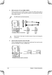
Connect the USB module cable to any of the system chassis. The USB module is purchased separately. 5. Internal audio connectors (4-pin CD, AUX) These connectors allow you to a slot opening at the back of these connectors, then install the module to... a CD-ROM, TV tuner, or MPEG card. USB connectors (10-1 pin USB56, USB78) These connectors are for USB 2.0 ports. USB+5V USB_P8USB_P8+ GND NC P4V800D-X ® USB56 1 P4V800D-X USB 2.0 connectors USB+5V USB_P6USB_P6+ GND NC USB78 1 USB+5V USB_P7USB_P7+ GND USB+5V USB_P5USB_P5+ GND Never connect a 1394 cable to the USB connectors...
Connect the USB module cable to any of the system chassis. The USB module is purchased separately. 5. Internal audio connectors (4-pin CD, AUX) These connectors allow you to a slot opening at the back of these connectors, then install the module to... a CD-ROM, TV tuner, or MPEG card. USB connectors (10-1 pin USB56, USB78) These connectors are for USB 2.0 ports. USB+5V USB_P8USB_P8+ GND NC P4V800D-X ® USB56 1 P4V800D-X USB 2.0 connectors USB+5V USB_P6USB_P6+ GND NC USB78 1 USB+5V USB_P7USB_P7+ GND USB+5V USB_P5USB_P5+ GND Never connect a 1394 cable to the USB connectors...

Motherboard DIY Troubleshooting Guide
Page 32
P4V800D-X ® GAME P4V800D-X Game connector The GAME/MIDI port module isi purchased separately. +5V J1B2 J1CY GND GND J1CX J1B1 +5V MIDI_IN J2B2 J2CY MIDI_OUT J2CX J2B1 +5V 1-22 Chapter 1: Product Introduction Connect the USB/GAME module cable to this connector, then install the module to a slot opening at the back of the system chassis. The GAME/MIDI port connects a joystick or game pad for playing games, and MIDI devices for a GAME/MIDI port. GAME port connector (16-1 pin GAME) This connector is for playing or editing audio files. 9.
P4V800D-X ® GAME P4V800D-X Game connector The GAME/MIDI port module isi purchased separately. +5V J1B2 J1CY GND GND J1CX J1B1 +5V MIDI_IN J2B2 J2CY MIDI_OUT J2CX J2B1 +5V 1-22 Chapter 1: Product Introduction Connect the USB/GAME module cable to this connector, then install the module to a slot opening at the back of the system chassis. The GAME/MIDI port connects a joystick or game pad for playing games, and MIDI devices for a GAME/MIDI port. GAME port connector (16-1 pin GAME) This connector is for playing or editing audio files. 9.
