User Manual
Page 3
... Email: [email protected] (for marketing requests only) Technical Support Hotline: MB/Others: +49-2102-9599-0 Notebook: +49-2102-9599-10 Fax: +49-2102-9599-11 Support (Email): www.asuscom.de/de/support (for online support) WWW: www.asuscom.de FTP: ftp.asuscom.de/pub/ASUSCOM ASUS P4T-F User's Manual 3
... Email: [email protected] (for marketing requests only) Technical Support Hotline: MB/Others: +49-2102-9599-0 Notebook: +49-2102-9599-10 Fax: +49-2102-9599-11 Support (Email): www.asuscom.de/de/support (for online support) WWW: www.asuscom.de FTP: ftp.asuscom.de/pub/ASUSCOM ASUS P4T-F User's Manual 3
User Manual
Page 11
... ON using your keyboard or mouse click. When auto throttling is enabled, the CPU with either the bundled ASUS PC Probe or Intel LDCM will enter the Soft-Off mode. • Peripheral Power Up: Keyboard or Mouse... power up to critical motherboard components. The onboard hardware ASUS ASIC in 3.8 Connectors for RPM and failure. This function ensures the best performance and reliability. • Fan Status...or as Windows 98/ Millenium, and Windows NT/2000, require much more information) button. ASUS P4T-F User's Manual 11
... ON using your keyboard or mouse click. When auto throttling is enabled, the CPU with either the bundled ASUS PC Probe or Intel LDCM will enter the Soft-Off mode. • Peripheral Power Up: Keyboard or Mouse... power up to critical motherboard components. The onboard hardware ASUS ASIC in 3.8 Connectors for RPM and failure. This function ensures the best performance and reliability. • Fan Status...or as Windows 98/ Millenium, and Windows NT/2000, require much more information) button. ASUS P4T-F User's Manual 11
User Manual
Page 12
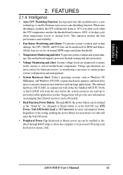
... Support Socket 423 for locations. 2. FEATURES MB Components 2. FEATURES 2.2 P4T-F Motherboard Components See opposite page for Pentium 4 Processors 2 Chipsets Intel 850 Memory Controller Hub (MCH 4 Intel I/O Controller Hub 2 (ICH2 11 2Mbit Firmware Hub (FWH 13 Low Pin Count (LPC) Super Multi-I/O...) 22 1 Line Out Connector Bottom) 22 1 Line In Connector Bottom) 22 1 Line Microphone Connector Bottom) 22 Hardware Monitoring ASUS onboard chipset 10 Power ATX Power Supply Connector 1 ATX 12V Power Supply Connector 3 Special Feature Auxillary Power Connector 6 Onboard LED...
... Support Socket 423 for locations. 2. FEATURES MB Components 2. FEATURES 2.2 P4T-F Motherboard Components See opposite page for Pentium 4 Processors 2 Chipsets Intel 850 Memory Controller Hub (MCH 4 Intel I/O Controller Hub 2 (ICH2 11 2Mbit Firmware Hub (FWH 13 Low Pin Count (LPC) Super Multi-I/O...) 22 1 Line Out Connector Bottom) 22 1 Line In Connector Bottom) 22 1 Line Microphone Connector Bottom) 22 Hardware Monitoring ASUS onboard chipset 10 Power ATX Power Supply Connector 1 ATX 12V Power Supply Connector 3 Special Feature Auxillary Power Connector 6 Onboard LED...
User Manual
Page 15
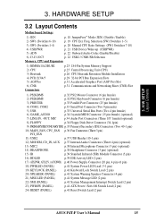
... Floppy Disk Drive Connector (34-1pin) 9) PRIMARY/SECONDARYIDE p.35 Primary/Secondary IDE Connectors (Two 40-1 pin) 10) MAIN_FAN, CPU_FAN p.36 Fan Connectors (Three 3 pin) PCI_FAN 11) USB2 p.37 USB Header (10-1 pin) 12) MODEM, CD_IN, AUX p.37 Internal Audio Connectors (Three 4 pin) (optional) 13) MIC2 p.38 Internal Microphone Connector (3 pin) (optional... System Management Interrupt Switch Lead (2 pin) 23) PWRSW (PANEL) p.41 ATX Power / Soft-Off Switch Lead (2 pin) 24) RESET (PANEL) p.41 Reset Switch Lead (2 pin) ASUS P4T-F User's Manual 15 H/W SETUP Layout Contents 3. Freq.
... Floppy Disk Drive Connector (34-1pin) 9) PRIMARY/SECONDARYIDE p.35 Primary/Secondary IDE Connectors (Two 40-1 pin) 10) MAIN_FAN, CPU_FAN p.36 Fan Connectors (Three 3 pin) PCI_FAN 11) USB2 p.37 USB Header (10-1 pin) 12) MODEM, CD_IN, AUX p.37 Internal Audio Connectors (Three 4 pin) (optional) 13) MIC2 p.38 Internal Microphone Connector (3 pin) (optional... System Management Interrupt Switch Lead (2 pin) 23) PWRSW (PANEL) p.41 ATX Power / Soft-Off Switch Lead (2 pin) 24) RESET (PANEL) p.41 Reset Switch Lead (2 pin) ASUS P4T-F User's Manual 15 H/W SETUP Layout Contents 3. Freq.
User Manual
Page 20
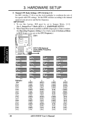
... ON 1 2 3 4 5 6 7 8 9 10 15.0x ON 1 2 3 4 5 6 7 8 9 10 19.0x ON 1 2 3 4 5 6 7 8 9 10 23.0x ON 1 2 3 4 5 6 7 8 9 10 12.0x Multiplier 8.0x 10.0x 11.0x 12.0x 13.0x 14.0x 15.0x 16.0x 17.0x 18.0x 19.0x 20.0x 21.0x 22.0x 23.0x ...] [OFF] [OFF] [OFF] [OFF] [ON] [ON] [ON] [ON] 4 [OFF] [OFF] [OFF] [OFF] [OFF] [OFF] [OFF] [OFF] [ON] [ON] [ON] [ON] [ON] [ON] [ON] [ON] 20 ASUS P4T-F User's Manual HARDWARE SETUP 3) Manual CPU Ratio Settings (SW1 Switches 1-4) Set SW1 switches (7-10) to use BIOS setup in BIOS Setup so you can set...
... ON 1 2 3 4 5 6 7 8 9 10 15.0x ON 1 2 3 4 5 6 7 8 9 10 19.0x ON 1 2 3 4 5 6 7 8 9 10 23.0x ON 1 2 3 4 5 6 7 8 9 10 12.0x Multiplier 8.0x 10.0x 11.0x 12.0x 13.0x 14.0x 15.0x 16.0x 17.0x 18.0x 19.0x 20.0x 21.0x 22.0x 23.0x ...] [OFF] [OFF] [OFF] [OFF] [ON] [ON] [ON] [ON] 4 [OFF] [OFF] [OFF] [OFF] [OFF] [OFF] [OFF] [OFF] [ON] [ON] [ON] [ON] [ON] [ON] [ON] [ON] 20 ASUS P4T-F User's Manual HARDWARE SETUP 3) Manual CPU Ratio Settings (SW1 Switches 1-4) Set SW1 switches (7-10) to use BIOS setup in BIOS Setup so you can set...
User Manual
Page 30
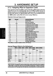
...AC'97 - shared shared -- -- used - IMPORTANT: If using PCI cards on shared slots, make the system unstable or cards inoperable. 30 ASUS P4T-F User's Manual shared - - - INT-G INT-H -- Conflicts will be exclusively assigned to operate. used - - - - - shared -... expansion cards. Standard Interrupt Assignments IRQ Priority Standard Function 0 1 System Timer 1 2 Keyboard Controller 2 N/A Programmable Interrupt 3* 11 Communications Port (COM2) 4* 12 Communications Port (COM1) 5* 13 Sound Card (sometimes LPT2) 6 14 Floppy Disk Controller 7*...
...AC'97 - shared shared -- -- used - IMPORTANT: If using PCI cards on shared slots, make the system unstable or cards inoperable. 30 ASUS P4T-F User's Manual shared - - - INT-G INT-H -- Conflicts will be exclusively assigned to operate. used - - - - - shared -... expansion cards. Standard Interrupt Assignments IRQ Priority Standard Function 0 1 System Timer 1 2 Keyboard Controller 2 N/A Programmable Interrupt 3* 11 Communications Port (COM2) 4* 12 Communications Port (COM1) 5* 13 Sound Card (sometimes LPT2) 6 14 Floppy Disk Controller 7*...

User Manual
Page 37
...P4T-F P4T-F USB Headers 1 6 USB2 5 1: USB Power 6: USB Power 2: USBP2- 7: USBP3- 3: USBP2+ 8: USBP3+ 10 4: GND 5: NC 9: GND 12) Internal Audio Connectors (4-pin MODEM, CD_IN, AUX) These connectors allow you to an open slot on the back panels are inadequate, a USB header is available for two additional USB ports. 3. HARDWARE SETUP 11...audio input from such audio-visual sources as a VIDEO or CD-ROM input, or MPEG card. H/W SETUP Connectors 3. P4T-F P4T-F Internal Audio Connectors MODEM Modem-Out Ground Ground Modem-In VIDEO (Green) AUX (White) CD1 (Black) Left Audio Channel ...
...P4T-F P4T-F USB Headers 1 6 USB2 5 1: USB Power 6: USB Power 2: USBP2- 7: USBP3- 3: USBP2+ 8: USBP3+ 10 4: GND 5: NC 9: GND 12) Internal Audio Connectors (4-pin MODEM, CD_IN, AUX) These connectors allow you to an open slot on the back panels are inadequate, a USB header is available for two additional USB ports. 3. HARDWARE SETUP 11...audio input from such audio-visual sources as a VIDEO or CD-ROM input, or MPEG card. H/W SETUP Connectors 3. P4T-F P4T-F Internal Audio Connectors MODEM Modem-Out Ground Ground Modem-In VIDEO (Green) AUX (White) CD1 (Black) Left Audio Channel ...

User Manual
Page 64
...; [200H-207H] [208H-20FH] Onboard MIDI I/O [330H-331H] This field sets the I /O address to configure the parallel port DMA channel for MIDI. Configuration options; [3 ,4, 5, 7, 9, 10, 11, 12, 14, 15] 4. BIOS SETUP I/O Device Config 64 ASUS P4T-F User's Manual 4.
...; [200H-207H] [208H-20FH] Onboard MIDI I/O [330H-331H] This field sets the I /O address to configure the parallel port DMA channel for MIDI. Configuration options; [3 ,4, 5, 7, 9, 10, 11, 12, 14, 15] 4. BIOS SETUP I/O Device Config 64 ASUS P4T-F User's Manual 4.
User Manual
Page 65
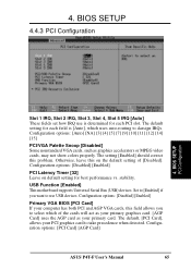
BIOS SETUP 4.4.3 PCI Configuration 4. Configuration options: [Auto] [NA] [3] [4] [5] [7] [9] [10] [11] [12] [14] [15] PCI/VGA Palette Snoop [Disabled] Some nonstandard VGA cards, such as your primary graphics card. [AGP Card] uses the AGP card as ... cards, may not show colors properly. The setting [Enabled] should correct this on default setting for each PCI slot. Configuration options: [PCI Card] [AGP Card] ASUS P4T-F User's Manual 65 BIOS SETUP PCI Configuration Slot 1 IRQ, Slot 2 IRQ, Slot 3, Slot 4, Slot 5 IRQ [Auto] These fields set how IRQ use USB devices. stability...
BIOS SETUP 4.4.3 PCI Configuration 4. Configuration options: [Auto] [NA] [3] [4] [5] [7] [9] [10] [11] [12] [14] [15] PCI/VGA Palette Snoop [Disabled] Some nonstandard VGA cards, such as your primary graphics card. [AGP Card] uses the AGP card as ... cards, may not show colors properly. The setting [Enabled] should correct this on default setting for each PCI slot. Configuration options: [PCI Card] [AGP Card] ASUS P4T-F User's Manual 65 BIOS SETUP PCI Configuration Slot 1 IRQ, Slot 2 IRQ, Slot 3, Slot 4, Slot 5 IRQ [Auto] These fields set how IRQ use USB devices. stability...