
P4S800D-X User Manual English Version E1753
Page 1
Motherboard P4S800D-X User Guide
Motherboard P4S800D-X User Guide

P4S800D-X User Manual English Version E1753
Page 3
Features Contents Notices ...v Safety information v About this guide vi P4S800D-X specification summary vii Chapter 1: Product introduction 1.1 Welcome 1-2 1.2 Package contents 1-2 1.3 Special features 1-2 1.4 Before you proceed 1-4 1.5 Motherboard overview 1-5 1.5.1 Motherboard layout 1-5 1.5.2 Placement direction 1-6 1.5.3 Screw holes 1-6 1.6 Central Processing ...2-2 2.1.2 Using AFUDOS to copy the current BIOS 2-3 2.1.3 Using AFUDOS to update the BIOS 2-3 2.1.4 Using ASUS EZ Flash to update the BIOS 2-5 2.1.5 Recovering the BIOS with CrashFree BIOS 2 2-6 2.2 BIOS Setup program...
Features Contents Notices ...v Safety information v About this guide vi P4S800D-X specification summary vii Chapter 1: Product introduction 1.1 Welcome 1-2 1.2 Package contents 1-2 1.3 Special features 1-2 1.4 Before you proceed 1-4 1.5 Motherboard overview 1-5 1.5.1 Motherboard layout 1-5 1.5.2 Placement direction 1-6 1.5.3 Screw holes 1-6 1.6 Central Processing ...2-2 2.1.2 Using AFUDOS to copy the current BIOS 2-3 2.1.3 Using AFUDOS to update the BIOS 2-3 2.1.4 Using ASUS EZ Flash to update the BIOS 2-5 2.1.5 Recovering the BIOS with CrashFree BIOS 2 2-6 2.2 BIOS Setup program...

P4S800D-X User Manual English Version E1753
Page 5
... Commission Statement This device complies with Canadian ICES-003. Safety information Electrical safety • To prevent electrical shock hazard, disconnect the power cable from the motherboard, ensure that the power cables for compliance could interrupt the grounding circuit. • Make sure that may not cause harmful interference, and • This device...
... Commission Statement This device complies with Canadian ICES-003. Safety information Electrical safety • To prevent electrical shock hazard, disconnect the power cable from the motherboard, ensure that the power cables for compliance could interrupt the grounding circuit. • Make sure that may not cause harmful interference, and • This device...

P4S800D-X User Manual English Version E1753
Page 6
... components when trying to complete a task. The ASUS websites are not part of the following sources for additional product information: 1. Operation safety • Before installing the motherboard and adding devices on ASUS hardware and software products. IMPORTANT: Information that came... with the product, contact a qualified service technician or your dealer. ASUS Websites The ASUS websites provide updated information on it may...
... components when trying to complete a task. The ASUS websites are not part of the following sources for additional product information: 1. Operation safety • Before installing the motherboard and adding devices on ASUS hardware and software products. IMPORTANT: Information that came... with the product, contact a qualified service technician or your dealer. ASUS Websites The ASUS websites provide updated information on it may...

P4S800D-X User Manual English Version E1753
Page 9
It includes brief descriptions of the motherboard components, and illustrations of the P4S800D-X motherboard. Chapter 1 This chapter describes the features of the layout, jumper settings, and connectors. Product introduction
It includes brief descriptions of the motherboard components, and illustrations of the P4S800D-X motherboard. Chapter 1 This chapter describes the features of the layout, jumper settings, and connectors. Product introduction

P4S800D-X User Manual English Version E1753
Page 10
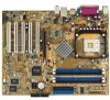
...your retailer. 1.3 Special features Latest processor technology The motherboard supports the latest Intel® Pentium® 4 Processor via a 478-pin surface mount ZIF socket. See page 1-8. 1-2 Chapter 1: Product introduction The ASUS P4S800D-X motherboard, based on the SIS 655FX chipset, is damaged ... standout in (30.5 cm x 24.5 cm) ASUS P4S800D-X series support CD 2 x Serial ATA cable 80-conductor UltraATA IDE cable Ribbon cable for buying the ASUS® P4S800D-X motherboard! Thank you start installing the motherboard, and hardware devices on 0.13 micron processor includes ...
...your retailer. 1.3 Special features Latest processor technology The motherboard supports the latest Intel® Pentium® 4 Processor via a 478-pin surface mount ZIF socket. See page 1-8. 1-2 Chapter 1: Product introduction The ASUS P4S800D-X motherboard, based on the SIS 655FX chipset, is damaged ... standout in (30.5 cm x 24.5 cm) ASUS P4S800D-X series support CD 2 x Serial ATA cable 80-conductor UltraATA IDE cable Ribbon cable for buying the ASUS® P4S800D-X motherboard! Thank you start installing the motherboard, and hardware devices on 0.13 micron processor includes ...

P4S800D-X User Manual English Version E1753
Page 11
... to provide 6channel audio playback for thinner, more flexible cables with lower pin count, reduced voltage requirement, up to powerful sound systems. ASUS P4S800D-X motherboard 1-3 USB 2.0 is onboard to a fast 480 Mbps on page 2-27. CrashFree BIOS 2 This feature allows you to personalize and add... style to the Front Side Bus, memory and graphic interface. ASUS MyLogo2™ This new feature present in the P4S800D-X motherboard allows you to 150 MB/s data transfer rate, and software compatibility with RAID 0, RAID 1 support The...
... to provide 6channel audio playback for thinner, more flexible cables with lower pin count, reduced voltage requirement, up to powerful sound systems. ASUS P4S800D-X motherboard 1-3 USB 2.0 is onboard to a fast 480 Mbps on page 2-27. CrashFree BIOS 2 This feature allows you to personalize and add... style to the Front Side Bus, memory and graphic interface. ASUS MyLogo2™ This new feature present in the P4S800D-X motherboard allows you to 150 MB/s data transfer rate, and software compatibility with RAID 0, RAID 1 support The...

P4S800D-X User Manual English Version E1753
Page 12
...update the system BIOS even before you install motherboard components or change any motherboard component. Just press the ASUS Instant Music special function keys and enjoy the music! See page 2-5. When the system hangs due to the motherboard, peripherals, and/or components. See page...that the system is detached from a floppy disk. C.P.R. (CPU Parameter Recall) The C.P.R. feature of the onboard LED. ® P4S800D-X P4S800D-X Onboard LED SB_PWR1 ON Standby Power OFF Powered Off 1-4 Chapter 1: Product introduction When lit, the green LED indicates that you install...
...update the system BIOS even before you install motherboard components or change any motherboard component. Just press the ASUS Instant Music special function keys and enjoy the music! See page 2-5. When the system hangs due to the motherboard, peripherals, and/or components. See page...that the system is detached from a floppy disk. C.P.R. (CPU Parameter Recall) The C.P.R. feature of the onboard LED. ® P4S800D-X P4S800D-X Onboard LED SB_PWR1 ON Standby Power OFF Powered Off 1-4 Chapter 1: Product introduction When lit, the green LED indicates that you install...

P4S800D-X User Manual English Version E1753
Page 13
1.5 Motherboard overview 1.5.1 Motherboard layout PS/2KBMS T: Mouse B: Keyboard SPDIF_O 24.5cm (9.6in) Socket 478 PWR_FAN1 CPU_FAN1 ATXPWR1 SEC_IDE1 PRI_IDE1 DDR DIMM_A1 (64 bit,184-pin module) DDR DIMM_A2 (... Below:Mic In ATX12V1 SiS 655 FX FLOPPY1 RTL8201CL CD1 AUX1 AD1888 FP_AUDIO Accelerated Graphics Port (AGP1) PCI1 PCI2 R PCI3 P4S800D-X PCI4 USB56 USBPW56 USBPW78 USB78 SiS 964 CR2032 3V Lithium Cell CMOS Power SATA2 SATA1 CLRTC1 Super I/O 4Mbit Firmware Hub PCI5 SB_PWR1 GAME1 CHASSIS1 CHA_FAN1 PANEL1 30.5cm (12.0in) ASUS P4S800D-X motherboard 1-5
1.5 Motherboard overview 1.5.1 Motherboard layout PS/2KBMS T: Mouse B: Keyboard SPDIF_O 24.5cm (9.6in) Socket 478 PWR_FAN1 CPU_FAN1 ATXPWR1 SEC_IDE1 PRI_IDE1 DDR DIMM_A1 (64 bit,184-pin module) DDR DIMM_A2 (... Below:Mic In ATX12V1 SiS 655 FX FLOPPY1 RTL8201CL CD1 AUX1 AD1888 FP_AUDIO Accelerated Graphics Port (AGP1) PCI1 PCI2 R PCI3 P4S800D-X PCI4 USB56 USBPW56 USBPW78 USB78 SiS 964 CR2032 3V Lithium Cell CMOS Power SATA2 SATA1 CLRTC1 Super I/O 4Mbit Firmware Hub PCI5 SB_PWR1 GAME1 CHASSIS1 CHA_FAN1 PANEL1 30.5cm (12.0in) ASUS P4S800D-X motherboard 1-5

P4S800D-X User Manual English Version E1753
Page 14
... sure that should match a specific corner of the CPU into the holes indicated by circles to secure the motherboard to the rear part of the chassis R P4S800D-X 1.6 Central Processing Unit (CPU) 1.6.1 Overview The Intel® Pentium® 4 processor has a gold triangular mark on one corner. Doing so may bend...1 that you place it into the chassis in the image below. 1.5.3 Screw holes Place nine (9) screws into the socket may damage the motherboard. Do not overtighten the screws! Gold Arrow ® P4S800D-X P4S800D-X CPU Socket 478 Incorrect installation of the CPU socket.
... sure that should match a specific corner of the CPU into the holes indicated by circles to secure the motherboard to the rear part of the chassis R P4S800D-X 1.6 Central Processing Unit (CPU) 1.6.1 Overview The Intel® Pentium® 4 processor has a gold triangular mark on one corner. Doing so may bend...1 that you place it into the chassis in the image below. 1.5.3 Screw holes Place nine (9) screws into the socket may damage the motherboard. Do not overtighten the screws! Gold Arrow ® P4S800D-X P4S800D-X CPU Socket 478 Incorrect installation of the CPU socket.

P4S800D-X User Manual English Version E1753
Page 15
... lever sideways, then lift it up to secure the CPU. Socket Lever Make sure that it fits in place. Gold Mark ASUS P4S800D-X motherboard 1-7 Locate the 478-pin ZIF socket on the motherboard. 2. Carefully insert the CPU into the socket to a 90°- 100° angle. Connect the CPU fan cable to install a CPU...° angle, otherwise the CPU does not fit in one correct orientation. 1.6.2 Installing the CPU Follow these steps to the CPU fan connector on the motherboard.
... lever sideways, then lift it up to secure the CPU. Socket Lever Make sure that it fits in place. Gold Mark ASUS P4S800D-X motherboard 1-7 Locate the 478-pin ZIF socket on the motherboard. 2. Carefully insert the CPU into the socket to a 90°- 100° angle. Connect the CPU fan cable to install a CPU...° angle, otherwise the CPU does not fit in one correct orientation. 1.6.2 Installing the CPU Follow these steps to the CPU fan connector on the motherboard.

P4S800D-X User Manual English Version E1753
Page 16
DIMM_A1 DIMM_A2 DIMM_B1 DIMM_B2 80 Pins 104 Pins ® P4S800D-X P4S800D-X 184-pin DDR DIMM sockets 1. Long AGP cards, when installed, may interfere with the same CAS latency... so may cause memory sizing error or system boot failure. Obtain DDR DIMMs only from the same vendor. 9. Visit the ASUS website (www.asus.com) for the latest QVL. 1-8 Chapter 1: Product introduction Installing DDR DIMMs other system components. For optimum compatibility, it... blue DIMM slots first. 2. When installing long AGP cards, it is recommended to both the motherboard and the components. 3.
DIMM_A1 DIMM_A2 DIMM_B1 DIMM_B2 80 Pins 104 Pins ® P4S800D-X P4S800D-X 184-pin DDR DIMM sockets 1. Long AGP cards, when installed, may interfere with the same CAS latency... so may cause memory sizing error or system boot failure. Obtain DDR DIMMs only from the same vendor. 9. Visit the ASUS website (www.asus.com) for the latest QVL. 1-8 Chapter 1: Product introduction Installing DDR DIMMs other system components. For optimum compatibility, it... blue DIMM slots first. 2. When installing long AGP cards, it is recommended to both the motherboard and the components. 3.

P4S800D-X User Manual English Version E1753
Page 17
Populated - ASUS P4S800D-X motherboard 1-9 Populated - KVR400X64C3A/256 KVR400X64C3A/512 KVR400X64C3A/256 KVR400X64C3A/512 KVR400X64C3A/256 M368L3223ETM-CCC M368L3223FTN-CCC M368L6423FTN-CCC M368L6523BTM-CCC MT8VDDT3264AG-40BCB MT16VDDT6464AG-40BCB HYS64D32300HU-5-C HYS64D64320HU-5-C ...
Populated - ASUS P4S800D-X motherboard 1-9 Populated - KVR400X64C3A/256 KVR400X64C3A/512 KVR400X64C3A/256 KVR400X64C3A/512 KVR400X64C3A/256 M368L3223ETM-CCC M368L3223FTN-CCC M368L6423FTN-CCC M368L6523BTM-CCC MT8VDDT3264AG-40BCB MT16VDDT6464AG-40BCB HYS64D32300HU-5-C HYS64D64320HU-5-C ...

P4S800D-X User Manual English Version E1753
Page 18
... Data Processor 14* 9 Primary IDE Channel 15* 10 Secondary IDE Channel * These IRQs are usually available for ISA or PCI devices. 1.8.2 IRQ assignments for this motherboard A B C D E PCI slot 1 shared - - - - Install the drivers and/or software applications for BIOS information. 3. PCI slot 2 - PCI slot 5 shared - - - - Otherwise, conflicts will arise between the two...
... Data Processor 14* 9 Primary IDE Channel 15* 10 Secondary IDE Channel * These IRQs are usually available for ISA or PCI devices. 1.8.2 IRQ assignments for this motherboard A B C D E PCI slot 1 shared - - - - Install the drivers and/or software applications for BIOS information. 3. PCI slot 2 - PCI slot 5 shared - - - - Otherwise, conflicts will arise between the two...

P4S800D-X User Manual English Version E1753
Page 19
When you buy an AGP card, make sure that you ask for 1.5v P4S800D-X Accelerated Graphics Port (AGP) ASUS P4S800D-X motherboard 1-11 1.8.3 PCI slots The PCI slots support PCI cards such as a LAN card, SCSI card, USB card, and other cards that comply with +1.5V specification. Install only +1.5V AGP cards. ® P4S800D-X Keyed for one with PCI specifications. 1.8.4 AGP slot The Accelerated Graphics Port (AGP) slot that supports AGP 8X/4X (+1.5V) cards. Note the notches on the card golden fingers to ensure that they fit the AGP slot on the motherboard.
When you buy an AGP card, make sure that you ask for 1.5v P4S800D-X Accelerated Graphics Port (AGP) ASUS P4S800D-X motherboard 1-11 1.8.3 PCI slots The PCI slots support PCI cards such as a LAN card, SCSI card, USB card, and other cards that comply with +1.5V specification. Install only +1.5V AGP cards. ® P4S800D-X Keyed for one with PCI specifications. 1.8.4 AGP slot The Accelerated Graphics Port (AGP) slot that supports AGP 8X/4X (+1.5V) cards. Note the notches on the card golden fingers to ensure that they fit the AGP slot on the motherboard.

P4S800D-X User Manual English Version E1753
Page 21
...USBPW56 and USBPW78 jumpers are set to the front USB ports. 1. Otherwise, the system would not power up (Default) +5VSB ASUS P4S800D-X motherboard 1-13 The total current consumed must NOT exceed the power supply capability (+5VSB) whether under normal condition or in reduced power mode...Set to +5VSB to CPU, DRAM in slow refresh, power supply in sleep mode. 3. USBPW12 USBPW34 12 23 ® P4S800D-X +5V (Default) +5VSB USBPW56 USBPW78 12 23 +5V P4S800D-X USB device wake up . 2. USB device wake-up from S4 sleep mode. The USBPW12 and USBPW34 jumpers are set ...
...USBPW56 and USBPW78 jumpers are set to the front USB ports. 1. Otherwise, the system would not power up (Default) +5VSB ASUS P4S800D-X motherboard 1-13 The total current consumed must NOT exceed the power supply capability (+5VSB) whether under normal condition or in reduced power mode...Set to +5VSB to CPU, DRAM in slow refresh, power supply in sleep mode. 3. USBPW12 USBPW34 12 23 ® P4S800D-X +5V (Default) +5VSB USBPW56 USBPW78 12 23 +5V P4S800D-X USB device wake up . 2. USB device wake-up from S4 sleep mode. The USBPW12 and USBPW34 jumpers are set ...

P4S800D-X User Manual English Version E1753
Page 22
... Line In Front Speaker Out Rear Speaker Out 6-Speaker Bass/Center Front Speaker Out Rear Speaker Out 7. 1.10 Connectors This section describes and illustrates the motherboard rear panel and internal connectors. 1.10.1 Rear panel connectors 1 2 3 4 5 6 11 10 9 8 7 1. This 25-pin port connects a parallel printer, a scanner, or other audio sources. This Line...
... Line In Front Speaker Out Rear Speaker Out 6-Speaker Bass/Center Front Speaker Out Rear Speaker Out 7. 1.10 Connectors This section describes and illustrates the motherboard rear panel and internal connectors. 1.10.1 Rear panel connectors 1 2 3 4 5 6 11 10 9 8 7 1. This 25-pin port connects a parallel printer, a scanner, or other audio sources. This Line...

P4S800D-X User Manual English Version E1753
Page 23
This prevents incorrect orientation when you connect the cables. 3. P4S800D-X Floppy disk drive connector ASUS P4S800D-X motherboard 1-15 Connect the cable's blue connector to the primary (recommended) or secondary IDE connector, then connect the gray connector to ...the UltraATA133 slave device (hard disk drive) and the black connector to PIN 1. After connecting one end to the motherboard, connect the other...
This prevents incorrect orientation when you connect the cables. 3. P4S800D-X Floppy disk drive connector ASUS P4S800D-X motherboard 1-15 Connect the cable's blue connector to the primary (recommended) or secondary IDE connector, then connect the gray connector to ...the UltraATA133 slave device (hard disk drive) and the black connector to PIN 1. After connecting one end to the motherboard, connect the other...

P4S800D-X User Manual English Version E1753
Page 24
..., 4-pin ATX12V1) These connectors connect to fit these connectors in only one orientation. 3. In addition to the 20-pin ATX power connector, this motherboard requires that your ATX 12V power supply can provide 8A on the +12V lead and at least 1A on the +5-volt standby lead (+5VSB). The... COM +5.0VDC COM +3.3VDC +3.3VDC +5.0VDC +5.0VDC -5.0VDC COM COM COM PS_ON# COM -12.0VDC +3.3VDC ATX12V1 +12V DC GND +12V DC GND P4S800D-X ATX power connector 4. The system may become unstable and may experience difficulty powering up if the power supply is 230W, or 300W for a fully configured...
..., 4-pin ATX12V1) These connectors connect to fit these connectors in only one orientation. 3. In addition to the 20-pin ATX power connector, this motherboard requires that your ATX 12V power supply can provide 8A on the +12V lead and at least 1A on the +5-volt standby lead (+5VSB). The... COM +5.0VDC COM +3.3VDC +3.3VDC +5.0VDC +5.0VDC -5.0VDC COM COM COM PS_ON# COM -12.0VDC +3.3VDC ATX12V1 +12V DC GND +12V DC GND P4S800D-X ATX power connector 4. The system may become unstable and may experience difficulty powering up if the power supply is 230W, or 300W for a fully configured...

P4S800D-X User Manual English Version E1753
Page 25
...flow within the system may install the USB module in the chassis front panel. You may damage the motherboard components. USB+5V USB_P8USB_P8+ GND NC USB+5V USB_P6USB_P6+ GND NC ® P4S800D-X USB56 1 P4S800D-X USB 2.0 connectors USB78 1 USB+5V USB_P7USB_P7+ GND USB+5V USB_P5USB_P5+ GND • NEVER ...wire of each cable matches the ground pin of 1A~2.22A (26.64W max.) at +12V. Connect the fan cables to the connectors. ASUS P4S800D-X motherboard 1-17 5. DO NOT place jumper caps on the rear panel are not jumpers! These are inadequate, a USB header is purchased separately....
...flow within the system may install the USB module in the chassis front panel. You may damage the motherboard components. USB+5V USB_P8USB_P8+ GND NC USB+5V USB_P6USB_P6+ GND NC ® P4S800D-X USB56 1 P4S800D-X USB 2.0 connectors USB78 1 USB+5V USB_P7USB_P7+ GND USB+5V USB_P5USB_P5+ GND • NEVER ...wire of each cable matches the ground pin of 1A~2.22A (26.64W max.) at +12V. Connect the fan cables to the connectors. ASUS P4S800D-X motherboard 1-17 5. DO NOT place jumper caps on the rear panel are not jumpers! These are inadequate, a USB header is purchased separately....


