P4PE-X/TE User Manual
Page 4
... 2-19 2.4.2 I/O Device Configuration 2-21 2.4.3 PCI Configuration 2-22 2.5 Power Menu 2-24 2.5.1 Power Up Control 2-26 2.5.2 Hardware Monitor 2-28 2.6 Boot Menu 2-29 2.7 Exit Menu 2-31 Chapter 3: Software support 3-1 3.1 Install an operating system 3-2 3.2 Support CD information 3-2 3.2.1 Running the support CD 3-2 3.2.2 Drivers menu 3-3 3.2.3 Utilities menu 3-4 3.2.4 ASUS Contact Information 3-5 iv
... 2-19 2.4.2 I/O Device Configuration 2-21 2.4.3 PCI Configuration 2-22 2.5 Power Menu 2-24 2.5.1 Power Up Control 2-26 2.5.2 Hardware Monitor 2-28 2.6 Boot Menu 2-29 2.7 Exit Menu 2-31 Chapter 3: Software support 3-1 3.1 Install an operating system 3-2 3.2 Support CD information 3-2 3.2.1 Running the support CD 3-2 3.2.2 Drivers menu 3-3 3.2.3 Utilities menu 3-4 3.2.4 ASUS Contact Information 3-5 iv

P4PE-X/TE User Manual
Page 9
P4PE-X/TE specifications summary CPU Chipset Front Side Bus (FSB) Memory Expansion slots IDE Audio LAN Special features Rear panel I/O Internal I/O Socket 478 for Intel® Pentium&#... ASUS EZ Flash ASUS CrashFree BIOS2 ASUS CPU Parameter Recall (C.P.R.) USB 2.0 ready Power Loss Restart SFS (Stepless Frequency Selection) CPU throttle Adjustable CPU Vcore 1 x Parallel port 2 x Serial ports 1 x PS/2 keyboard port 1 x PS/2 mouse port 4 x USB 2.0/USB 1.1 ports 1 x RJ-45 port Line In/Line Out/Microphone ports 1 x USB 2.0/1.1 connector for up to 2GB memory Supports...
P4PE-X/TE specifications summary CPU Chipset Front Side Bus (FSB) Memory Expansion slots IDE Audio LAN Special features Rear panel I/O Internal I/O Socket 478 for Intel® Pentium&#... ASUS EZ Flash ASUS CrashFree BIOS2 ASUS CPU Parameter Recall (C.P.R.) USB 2.0 ready Power Loss Restart SFS (Stepless Frequency Selection) CPU throttle Adjustable CPU Vcore 1 x Parallel port 2 x Serial ports 1 x PS/2 keyboard port 1 x PS/2 mouse port 4 x USB 2.0/USB 1.1 ports 1 x RJ-45 port Line In/Line Out/Microphone ports 1 x USB 2.0/1.1 connector for up to 2GB memory Supports...
P4PE-X/TE User Manual
Page 10
x DMI 2.0, WOL/WOR by PME, chassis intrusion, SMBus Form Factor ATX form factor: 12 in x 9.0 in (30.5 cm x 22.9 cm) Support CD contents Device drivers ASUS PC Probe ASUS LiveUpdate Trend Micro™ PC-cillin 2002 anti-virus software (OEM version) * Specifications are subject to change without notice. P4PE-X/TE specifications summary BIOS features 2Mb Flash ROM, Award BIOS, TCAV, PnP, DMI2.0, SM BIOS2.3, ASUS C.P.R., ASUS EZ Flash, ASUS CrashFree BIOS2 Industry standard PCI 2.2, USB 2.0 Manageability WfM 2.0.
x DMI 2.0, WOL/WOR by PME, chassis intrusion, SMBus Form Factor ATX form factor: 12 in x 9.0 in (30.5 cm x 22.9 cm) Support CD contents Device drivers ASUS PC Probe ASUS LiveUpdate Trend Micro™ PC-cillin 2002 anti-virus software (OEM version) * Specifications are subject to change without notice. P4PE-X/TE specifications summary BIOS features 2Mb Flash ROM, Award BIOS, TCAV, PnP, DMI2.0, SM BIOS2.3, ASUS C.P.R., ASUS EZ Flash, ASUS CrashFree BIOS2 Industry standard PCI 2.2, USB 2.0 Manageability WfM 2.0.

P4PE-X/TE User Manual
Page 12
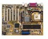
... list below. *Overclocking mode 1.2 Package contents Check your P4PE-X/TE package for more information. 1-2 Chapter 1: Product introduction The motherboard incorporates the Intel® Pentium® 4 Processor in (30.5 cm x 22.9 cm) ASUS P4PE-X/TE series support CD 1 x 80-conductor ribbon cables for UltraDMA/66.../100/133 IDE drives 1 x Ribbon cable for buying the ASUS® P4PE-X/TE motherboard! Before you for a 3.5-inch floppy drive 1 x I/O shield ...
... list below. *Overclocking mode 1.2 Package contents Check your P4PE-X/TE package for more information. 1-2 Chapter 1: Product introduction The motherboard incorporates the Intel® Pentium® 4 Processor in (30.5 cm x 22.9 cm) ASUS P4PE-X/TE series support CD 1 x 80-conductor ribbon cables for UltraDMA/66.../100/133 IDE drives 1 x Ribbon cable for buying the ASUS® P4PE-X/TE motherboard! Before you for a 3.5-inch floppy drive 1 x I/O shield ...
P4PE-X/TE User Manual
Page 13
... chip. ASUS P4PE-X/TE motherboard user guide 1-3 See page 1-12 for each parameter. See page 1-18. A digital audio connector is onboard to use a DOS-based utility or boot from 12 Mbps on USB 1.1 to support 10BASE-T/100BASE-TX networking protocol. DDR memory support Employing the Double Data Rate (DDR) memory technology, the P4PE-X/TE motherboard supports up to...
... chip. ASUS P4PE-X/TE motherboard user guide 1-3 See page 1-12 for each parameter. See page 1-18. A digital audio connector is onboard to use a DOS-based utility or boot from 12 Mbps on USB 1.1 to support 10BASE-T/100BASE-TX networking protocol. DDR memory support Employing the Double Data Rate (DDR) memory technology, the P4PE-X/TE motherboard supports up to...
P4PE-X/TE User Manual
Page 15
...reminder to an ATX +12V power supply. This Low Pin Count (LPC) interface provides the commonly used Super I /O controller. The chipset supports a highperformance floppy disk controller for efficient utilization of the IDE ribbon cable. 8 South bridge controller. The MCH interconnects to six USB 2.0/1.1 ports... These three 184-pin DIMM sockets support up to the south bridge ICH4 via the Intel® proprietary Hub Interface. 4 DDR DIMM sockets. This power connector connects the 4-pin 12V plug from the ATX 12V power supply. 2 CPU socket. ASUS P4PE-X/TE motherboard user guide 1-5
...reminder to an ATX +12V power supply. This Low Pin Count (LPC) interface provides the commonly used Super I /O controller. The chipset supports a highperformance floppy disk controller for efficient utilization of the IDE ribbon cable. 8 South bridge controller. The MCH interconnects to six USB 2.0/1.1 ports... These three 184-pin DIMM sockets support up to the south bridge ICH4 via the Intel® proprietary Hub Interface. 4 DDR DIMM sockets. This power connector connects the 4-pin 12V plug from the ATX 12V power supply. 2 CPU socket. ASUS P4PE-X/TE motherboard user guide 1-5

P4PE-X/TE User Manual
Page 16
... These two 4-pin Universal Serial Bus (USB) ports are available for connecting USB 2.0 devices. 24 Serial ports. The Realtek® RTC8100C controller supports 10BASE-T/ 100BASE-TX networking. 16 AGP slot. In 6-channel mode, the function of this jack becomes Rear Speaker Out. This Mic (pink) ...5.1 surround sound, S/PDIF output, AUX and Line In stereo inputs, integrated headphone amplifier, greater than 90dB dynamic range, and stereo Mic PREAMP support. 15 LAN controller. This Line In (light blue) jack connects a tape player or other devices. 19 RJ-45 port. In 6-channel ...
... These two 4-pin Universal Serial Bus (USB) ports are available for connecting USB 2.0 devices. 24 Serial ports. The Realtek® RTC8100C controller supports 10BASE-T/ 100BASE-TX networking. 16 AGP slot. In 6-channel mode, the function of this jack becomes Rear Speaker Out. This Mic (pink) ...5.1 surround sound, S/PDIF output, AUX and Line In stereo inputs, integrated headphone amplifier, greater than 90dB dynamic range, and stereo Mic PREAMP support. 15 LAN controller. This Line In (light blue) jack connects a tape player or other devices. 19 RJ-45 port. In 6-channel ...
P4PE-X/TE User Manual
Page 20
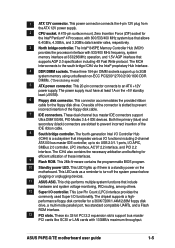
...Processing Unit (CPU) 1.8.1 Overview The motherboard comes with 512KB L2 cache on Hyper-Threading Technology, visit www.intel.com/ info/hyperthreading. This processor supports 800*/533/400MHz front side bus (FSB), and allows data transfer rates of the CPU socket. This mark indicates the processor Pin 1 that ...page 2-17. 3. Gold Mark Incorrect installation of the CPU into the socket may bend the pins and severely damage the CPU! The socket is supported under Windows XP and Linux 2.4.x (kernel) and later versions only. Note in the 478-pin package with a surface mount 478-pin Zero ...
...Processing Unit (CPU) 1.8.1 Overview The motherboard comes with 512KB L2 cache on Hyper-Threading Technology, visit www.intel.com/ info/hyperthreading. This processor supports 800*/533/400MHz front side bus (FSB), and allows data transfer rates of the CPU socket. This mark indicates the processor Pin 1 that ...page 2-17. 3. Gold Mark Incorrect installation of the CPU into the socket may bend the pins and severely damage the CPU! The socket is supported under Windows XP and Linux 2.4.x (kernel) and later versions only. Note in the 478-pin package with a surface mount 478-pin Zero ...

P4PE-X/TE User Manual
Page 22
... DDR module can only run at the same time but neither one can be x16 DDR module. 1-12 Chapter 1: Product introduction These sockets support up . 2. Use only the following combinations to install DDR DIMMs. Otherwise, the system may install any DDR DIMMs with 64MB, 128MB, 256MB...memory chips) are not supported on this motherboard. 3. Double-sided DIMM None SS 1. 1.9 System memory The motherboard comes with 800MHz FSB. You may install single-sided DIMMs into DIMM2 and DIMM3 sockets at 333MHz or lower frequency. ® P4PE-X/TE 80 Pins 104 Pins P4PE-X/TE 184-Pin DDR DIMM ...
... DDR module can only run at the same time but neither one can be x16 DDR module. 1-12 Chapter 1: Product introduction These sockets support up . 2. Use only the following combinations to install DDR DIMMs. Otherwise, the system may install any DDR DIMMs with 64MB, 128MB, 256MB...memory chips) are not supported on this motherboard. 3. Double-sided DIMM None SS 1. 1.9 System memory The motherboard comes with 800MHz FSB. You may install single-sided DIMMs into DIMM2 and DIMM3 sockets at 333MHz or lower frequency. ® P4PE-X/TE 80 Pins 104 Pins P4PE-X/TE 184-Pin DDR DIMM ...

P4PE-X/TE User Manual
Page 23
This motherboard supports different memory frequencies depending on the socket. 3. DIMM M2G9I08AFATT9F081AA4T 1 MT16VDDT3264AG-403B2 1 77.10636.465 1 TS32MLD64V4F3 1 MDOSS6F3G31JB1EAE 1 M368L3223ETM-CCC 1 HYMD232646B8J-D43 AA 1 Obtain DDR DIMMs only from ASUS qualified vendors to unplug the power supply before...retaining clips snap back in place and the DIMM is properly seated. Unlocked Retaining Clip ASUS P4PE-X/TE motherboard user guide 1-13 Visit the ASUS website (www.asus.com) for the latest qualified vendors list (QVL). 1.9.2 Installing a DIMM Make sure ...
This motherboard supports different memory frequencies depending on the socket. 3. DIMM M2G9I08AFATT9F081AA4T 1 MT16VDDT3264AG-403B2 1 77.10636.465 1 TS32MLD64V4F3 1 MDOSS6F3G31JB1EAE 1 M368L3223ETM-CCC 1 HYMD232646B8J-D43 AA 1 Obtain DDR DIMMs only from ASUS qualified vendors to unplug the power supply before...retaining clips snap back in place and the DIMM is properly seated. Unlocked Retaining Clip ASUS P4PE-X/TE motherboard user guide 1-13 Visit the ASUS website (www.asus.com) for the latest qualified vendors list (QVL). 1.9.2 Installing a DIMM Make sure ...

P4PE-X/TE User Manual
Page 24
...- - - shared - - shared - - - - - - - - - - When using PCI cards on the system and change the necessary BIOS settings, if any. NOTE: The AGP slot supports only 1.5V AGP cards. 2. Refer to the card. Onboard USB 2.0 controller - - shared - - - - - - shared - - - - - - - - - -- - - - - -- - shared... - - - Turn on shared slots, ensure that the drivers support "Share IRQ" or that came with the chassis. PCI slot 5 -- Onboard USB controller HC1 - - shared - - See Chapter 2 for this motherboard AB PCI slot 1 --...
...- - - shared - - shared - - - - - - - - - - When using PCI cards on the system and change the necessary BIOS settings, if any. NOTE: The AGP slot supports only 1.5V AGP cards. 2. Refer to the card. Onboard USB 2.0 controller - - shared - - - - - - shared - - - - - - - - - -- - - - - -- - shared... - - - Turn on shared slots, ensure that the drivers support "Share IRQ" or that came with the chassis. PCI slot 5 -- Onboard USB controller HC1 - - shared - - See Chapter 2 for this motherboard AB PCI slot 1 --...

P4PE-X/TE User Manual
Page 26
... +5VSB. The USBPW12 and USBPW34 jumpers are set to pins 1-2 (+5V) by default because not all computers have the appropriate power supply to support this LED to CPU, DRAM in slow refresh, power supply in reduced power mode). Otherwise, the system would not power up , try reversing the... that can connect to wake up . The USBPW56 jumper is for the rear USB ports. USBPW12 12 23 ® P4PE-X/TE +5V (Default) +5VSB USBPW34 USBPW56 12 23 +5V P4PE-X/TE USB Device Wake Up (Default) +5VSB 1.12 Connectors This section describes and illustrates the internal connectors on the +5VSB ...
... +5VSB. The USBPW12 and USBPW34 jumpers are set to pins 1-2 (+5V) by default because not all computers have the appropriate power supply to support this LED to CPU, DRAM in slow refresh, power supply in reduced power mode). Otherwise, the system would not power up , try reversing the... that can connect to wake up . The USBPW56 jumper is for the rear USB ports. USBPW12 12 23 ® P4PE-X/TE +5V (Default) +5VSB USBPW34 USBPW56 12 23 +5V P4PE-X/TE USB Device Wake Up (Default) +5VSB 1.12 Connectors This section describes and illustrates the internal connectors on the +5VSB ...
P4PE-X/TE User Manual
Page 27
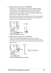
...1 P4PE-X/TE Floppy Disk Drive Connector ASUS P4PE-X/TE motherboard user guide 1-17 Chassis intrusion connector (4-1 pin CHASSIS1) This lead is removed to prevent incorrect insertion when using ribbon cables with pin 5 plug). Floppy disk drive connector (34-1 pin FLOPPY1) This connector supports the... triggers and sends a high-level signal to this lead to PIN 1. CHASSIS1 ® P4PE-X/TE (Default) P4PE-X/TE Chassis Alarm Lead 3. +5VSB_MB Chassis Signal GND 2. FLOPPY1 ® P4PE-X/TE NOTE: Orient the red markings on the floppy ribbon cable to record a chassis intrusion event...
...1 P4PE-X/TE Floppy Disk Drive Connector ASUS P4PE-X/TE motherboard user guide 1-17 Chassis intrusion connector (4-1 pin CHASSIS1) This lead is removed to prevent incorrect insertion when using ribbon cables with pin 5 plug). Floppy disk drive connector (34-1 pin FLOPPY1) This connector supports the... triggers and sends a high-level signal to this lead to PIN 1. CHASSIS1 ® P4PE-X/TE (Default) P4PE-X/TE Chassis Alarm Lead 3. +5VSB_MB Chassis Signal GND 2. FLOPPY1 ® P4PE-X/TE NOTE: Orient the red markings on the floppy ribbon cable to record a chassis intrusion event...
P4PE-X/TE User Manual
Page 28
... orientation when you must configure the second drive as a slave device by setting its jumper accordingly. SEC_IDE PRI_IDE PIN 1 PIN 1 P4PE-X/TE IDE Connectors 5. IDE connectors (40-1 pin PRI_IDE, SEC_IDE) This connector supports the provided UltraDMA/100/66 IDE hard disk ribbon cable. Connect the cable's blue connector to the primary (recommended) or...
... orientation when you must configure the second drive as a slave device by setting its jumper accordingly. SEC_IDE PRI_IDE PIN 1 PIN 1 P4PE-X/TE IDE Connectors 5. IDE connectors (40-1 pin PRI_IDE, SEC_IDE) This connector supports the provided UltraDMA/100/66 IDE hard disk ribbon cable. Connect the cable's blue connector to the primary (recommended) or...
P4PE-X/TE User Manual
Page 30
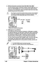
.... The USB header complies with USB 2.0 specification that supports up to the fan connectors on the rear panel are not jumpers! This speed advantage over the conventional 12 Mbps on the fan connectors! ® P4PE-X/TE GND +12V Rotation CPU_FAN1 CHA_FAN1 Rotation +12V GND P4PE-X/TE 12-Volt Fan Connectors 9. DO NOT place jumper caps...
.... The USB header complies with USB 2.0 specification that supports up to the fan connectors on the rear panel are not jumpers! This speed advantage over the conventional 12 Mbps on the fan connectors! ® P4PE-X/TE GND +12V Rotation CPU_FAN1 CHA_FAN1 Rotation +12V GND P4PE-X/TE 12-Volt Fan Connectors 9. DO NOT place jumper caps...

P4PE-X/TE User Manual
Page 31
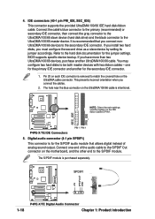
...are shorted with jumper caps. AGND +5VA BLINE_OUT_R BLINE_OUT_L ® P4PE-X/TE FP_AUDIO1 MIC2 MICPWR Line out_R NC Line out_L P4PE-X/TE Front Panel Audio Connector 11. GAME/MIDI connector (16-1 pin GAME1) This connector supports a GAME/MIDI module. Connect an optional GAME/MIDI cable to ... audio connector (10-1 pin FP_AUDIO1) This is purchased separately. ® P4PE-X/TE P4PE-X/TE Game Connector +5V J1B2 J1CY GND GND J1CX J1B1 +5V GAME1 1 MIDI_IN J2B2 J2CY MIDI_OUT J2CX J2B1 +5V ASUS P4PE-X/TE motherboard user guide 1-21 The USB2.0/GAME module is an interface for playing...
...are shorted with jumper caps. AGND +5VA BLINE_OUT_R BLINE_OUT_L ® P4PE-X/TE FP_AUDIO1 MIC2 MICPWR Line out_R NC Line out_L P4PE-X/TE Front Panel Audio Connector 11. GAME/MIDI connector (16-1 pin GAME1) This connector supports a GAME/MIDI module. Connect an optional GAME/MIDI cable to ... audio connector (10-1 pin FP_AUDIO1) This is purchased separately. ® P4PE-X/TE P4PE-X/TE Game Connector +5V J1B2 J1CY GND GND J1CX J1B1 +5V GAME1 1 MIDI_IN J2B2 J2CY MIDI_OUT J2CX J2B1 +5V ASUS P4PE-X/TE motherboard user guide 1-21 The USB2.0/GAME module is an interface for playing...
P4PE-X/TE User Manual
Page 36
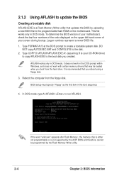
... boot disk you reboot using a floppy disk. 3. If the word "unknown" appears after Flash Memory:, the memory chip is either not programmable or is not supported by the ACPI BIOS and therefore, cannot be loaded when you boot from the floppy disk. In DOS mode, type A:\AFLASH to run AFLASH. 2.1.2 Using...
... boot disk you reboot using a floppy disk. 3. If the word "unknown" appears after Flash Memory:, the memory chip is either not programmable or is not supported by the ACPI BIOS and therefore, cannot be loaded when you boot from the floppy disk. In DOS mode, type A:\AFLASH to run AFLASH. 2.1.2 Using...

P4PE-X/TE User Manual
Page 38
... this may not boot. If you encounter problems while updating the new BIOS, DO NOT turn off the system because this happens, call the ASUS service center for support. 2-6 Chapter 2: BIOS information When the programming is updated automatically only when necessary. 6. The utility starts to the boot disk. If the Flash Memory...
... this may not boot. If you encounter problems while updating the new BIOS, DO NOT turn off the system because this happens, call the ASUS service center for support. 2-6 Chapter 2: BIOS information When the programming is updated automatically only when necessary. 6. The utility starts to the boot disk. If the Flash Memory...
P4PE-X/TE User Manual
Page 39
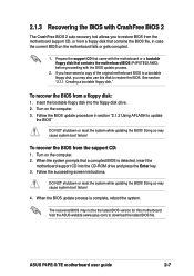
... reset the system while updating the BIOS! The recovered BIOS may also use this motherboard. Turn on the computer. 2. Turn on the computer. 3. ASUS P4PE-X/TE motherboard user guide 2-7 See section "2.1.1 Creating a bootable floppy disk." To recover the BIOS from a floppy disk that contains the BIOS file, in... the BIOS. Insert the bootable floppy disk into the CD-ROM drive and press the Enter key. 3. To recover the BIOS from the support CD: 1. Doing so may cause system boot failure! 4. If you have saved a copy of the original motherboard BIOS to a bootable floppy...
... reset the system while updating the BIOS! The recovered BIOS may also use this motherboard. Turn on the computer. 2. Turn on the computer. 3. ASUS P4PE-X/TE motherboard user guide 2-7 See section "2.1.1 Creating a bootable floppy disk." To recover the BIOS from a floppy disk that contains the BIOS file, in... the BIOS. Insert the bootable floppy disk into the CD-ROM drive and press the Enter key. 3. To recover the BIOS from the support CD: 1. Doing so may cause system boot failure! 4. If you have saved a copy of the original motherboard BIOS to a bootable floppy...
P4PE-X/TE User Manual
Page 41
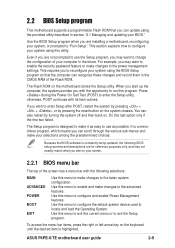
2.2 BIOS Setup program This motherboard supports a programmable Flash ROM that the computer can update using the provided utility described in section "2.1 Managing and updating your screen. 2.2.1 BIOS menu bar The top ... this last option only if the first two failed. You can scroll through the various sub-menus and make changes to make it as possible. ASUS P4PE-X/TE motherboard user guide 2-9 Press during the Power-On Self Test (POST) to enter the Setup utility, otherwise, POST continues with the opportunity to run this...
2.2 BIOS Setup program This motherboard supports a programmable Flash ROM that the computer can update using the provided utility described in section "2.1 Managing and updating your screen. 2.2.1 BIOS menu bar The top ... this last option only if the first two failed. You can scroll through the various sub-menus and make changes to make it as possible. ASUS P4PE-X/TE motherboard user guide 2-9 Press during the Power-On Self Test (POST) to enter the Setup utility, otherwise, POST continues with the opportunity to run this...


