
P4P8X user's manual English version E1299
Page 3
Features Contents Notices v Safety information vi About this guide vii ASUS contact information viii P4P8X specifications summary ix Chapter 1: Product introduction 1.1 Welcome 1-2 1.2 Package contents 1-2 1.3 Special features 1-3 1.4 Motherboard ... 1.11 Jumpers 1-19 1.12 Connectors 1-21 Chapter 2: BIOS information 2.1 Managing and updating your BIOS 2-2 2.1.1 Creating a bootable floppy disk 2-2 2.1.2 Using AFUDOS to update the BIOS 2-2 2.1.3 Using ASUS EZ Flash to update the BIOS 2-4 2.1.4 Recovering the BIOS with CrashFree BIOS 2 ....... 2-5 2.2 BIOS Setup program 2-7 iii
Features Contents Notices v Safety information vi About this guide vii ASUS contact information viii P4P8X specifications summary ix Chapter 1: Product introduction 1.1 Welcome 1-2 1.2 Package contents 1-2 1.3 Special features 1-3 1.4 Motherboard ... 1.11 Jumpers 1-19 1.12 Connectors 1-21 Chapter 2: BIOS information 2.1 Managing and updating your BIOS 2-2 2.1.1 Creating a bootable floppy disk 2-2 2.1.2 Using AFUDOS to update the BIOS 2-2 2.1.3 Using ASUS EZ Flash to update the BIOS 2-4 2.1.4 Recovering the BIOS with CrashFree BIOS 2 ....... 2-5 2.2 BIOS Setup program 2-7 iii

P4P8X user's manual English version E1299
Page 4
Contents Safeguards 2.2.1 2.2.2 2.2.3 2.2.4 2.2.5 2.2.6 2.2.7 2.2.8 2.2.9 BIOS menu screen 2-8 Menu bar 2-8 Navigation keys 2-8 Menu items 2-9 Sub-menu items 2-9 Configuration fields 2-9 Pop-up window 2-9 Scroll bar 2-9 General ...menu 2-25 2.5.1 Suspend Mode [Auto 2-25 2.5.2 Repost Video on S3 Resume [No 2-25 2.5.3 ACPI 2.0 Support [No 2-25 2.5.4 ACPI APIC Support [Enabled 2-25 2.5.5 BIOS -> AML ACPI Table [Enabled 2-25 2.5.6 APM Configuration 2-26 2.5.7 Hardware Monitor 2-28 2.6 Boot menu 2-29 2.6.1 Boot Device Priority 2-29 2.6.2 Boot Settings Configuration 2-30 2.6.3...
Contents Safeguards 2.2.1 2.2.2 2.2.3 2.2.4 2.2.5 2.2.6 2.2.7 2.2.8 2.2.9 BIOS menu screen 2-8 Menu bar 2-8 Navigation keys 2-8 Menu items 2-9 Sub-menu items 2-9 Configuration fields 2-9 Pop-up window 2-9 Scroll bar 2-9 General ...menu 2-25 2.5.1 Suspend Mode [Auto 2-25 2.5.2 Repost Video on S3 Resume [No 2-25 2.5.3 ACPI 2.0 Support [No 2-25 2.5.4 ACPI APIC Support [Enabled 2-25 2.5.5 BIOS -> AML ACPI Table [Enabled 2-25 2.5.6 APM Configuration 2-26 2.5.7 Hardware Monitor 2-28 2.6 Boot menu 2-29 2.6.1 Boot Device Priority 2-29 2.6.2 Boot Settings Configuration 2-30 2.6.3...
P4P8X user's manual English version E1299
Page 9
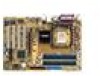
P4P8X specifications summary CCPPUU Chipset Chipset Front Side Bus (FSB) FMreomntoSryide Bus (FSB) Memory Expansion slots Expansion slots ISDtEorage RAID IDE / Serial ATA (optional) AI Audio IEEE 1394 (optional) AI Net Audio (optional) ASUS BIOS Features LAN (optional) AI Overclocking Special...2 x Serial ATA ADI AD1985 6-channel audio CODEC 1 x S/PDIF out 3COM 3C940 Gbit PCI LAN controller ASUS CrashFree BIOS 2 ASUS Q-Fan Technology Intelligent CPU frequency tuner ASUS JumperFree Adjustable CPU VCORE, memory and AGP voltages SFS (Stepless Frequency Selection) from 100MHz to 400MHz at 1MHz ...
P4P8X specifications summary CCPPUU Chipset Chipset Front Side Bus (FSB) FMreomntoSryide Bus (FSB) Memory Expansion slots Expansion slots ISDtEorage RAID IDE / Serial ATA (optional) AI Audio IEEE 1394 (optional) AI Net Audio (optional) ASUS BIOS Features LAN (optional) AI Overclocking Special...2 x Serial ATA ADI AD1985 6-channel audio CODEC 1 x S/PDIF out 3COM 3C940 Gbit PCI LAN controller ASUS CrashFree BIOS 2 ASUS Q-Fan Technology Intelligent CPU frequency tuner ASUS JumperFree Adjustable CPU VCORE, memory and AGP voltages SFS (Stepless Frequency Selection) from 100MHz to 400MHz at 1MHz ...

P4P8X user's manual English version E1299
Page 10
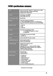
P4P8X specifications summary Internal I/O BIOS features Industry standard Manageability Form Factor Support CD contents 2 x USB 2.0/1.1 connector for 4 additional USB ports CPU/Chassis/Power fan connectors 20-pin/4-pin ATX 12V power connectors Chassis intrusion GAME connector S/PDIF out connector CD/AUX/Modem audio connectors Front panel audio connector 4Mb Flash ROM, AMI BIOS..., PnP, DMI2.0, ACPI, SM BIOS2.3, CrashFree BIOS 2, ASUS EZ Flash PCI 2.2, USB 2.0 DMI 2.0, WOL/WOR by PME, WO_USB, WO_KB/MS...
P4P8X specifications summary Internal I/O BIOS features Industry standard Manageability Form Factor Support CD contents 2 x USB 2.0/1.1 connector for 4 additional USB ports CPU/Chassis/Power fan connectors 20-pin/4-pin ATX 12V power connectors Chassis intrusion GAME connector S/PDIF out connector CD/AUX/Modem audio connectors Front panel audio connector 4Mb Flash ROM, AMI BIOS..., PnP, DMI2.0, ACPI, SM BIOS2.3, CrashFree BIOS 2, ASUS EZ Flash PCI 2.2, USB 2.0 DMI 2.0, WOL/WOR by PME, WO_USB, WO_KB/MS...

P4P8X user's manual English version E1299
Page 13
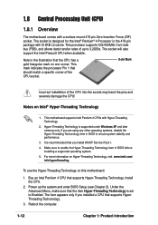
.... AGP 8X support The motherboard also mounts an AGP 8X interface (a.k.a. No need to 3.2GHz core frequencies. ASUS EZ Flash BIOS With the ASUS EZ Flash, you to 100 meters and helps users improve network quality. ASUS P4P8X motherboard user guide 1-3 1.3 Special features Latest processor technology The motherboard supports the Intel® Pentium® 4 / Celeron...
.... AGP 8X support The motherboard also mounts an AGP 8X interface (a.k.a. No need to 3.2GHz core frequencies. ASUS EZ Flash BIOS With the ASUS EZ Flash, you to 100 meters and helps users improve network quality. ASUS P4P8X motherboard user guide 1-3 1.3 Special features Latest processor technology The motherboard supports the Intel® Pentium® 4 / Celeron...

P4P8X user's manual English version E1299
Page 17
... 533/400 MHz frequency, system memory interface at least 1A on the motherboard. 1 ATX 12V connector. This 4Mb firmware contains the programmable BIOS program. 12 South bridge controller. ASUS P4P8X motherboard user guide 1-7 The Intel® 82865P Memory Controller Hub (MCH) provides the processor interface with 800/533/400 MHz system bus that...
... 533/400 MHz frequency, system memory interface at least 1A on the motherboard. 1 ATX 12V connector. This 4Mb firmware contains the programmable BIOS program. 12 South bridge controller. ASUS P4P8X motherboard user guide 1-7 The Intel® 82865P Memory Controller Hub (MCH) provides the processor interface with 800/533/400 MHz system bus that...
P4P8X user's manual English version E1299
Page 22
Note in BIOS before installing a supported operating system. 5. This motherboard supports Intel Pentium 4 CPUs with a surface mount 478-pin Zero Insertion Force (ZIF) socket. If you installed a CPU ... 533/400MHz front side bus (FSB), and allows data transfer rates of up the system and enter BIOS Setup (see Chapter 2). Hyper-Threading Technology is designed for the Intel® Pentium® 4 Processor in BIOS to Enabled. Buy an Intel Pentium 4 CPU that the CPU has a gold triangular mark on Intel®...
Note in BIOS before installing a supported operating system. 5. This motherboard supports Intel Pentium 4 CPUs with a surface mount 478-pin Zero Insertion Force (ZIF) socket. If you installed a CPU ... 533/400MHz front side bus (FSB), and allows data transfer rates of up the system and enter BIOS Setup (see Chapter 2). Hyper-Threading Technology is designed for the Intel® Pentium® 4 Processor in BIOS to Enabled. Buy an Intel Pentium 4 CPU that the CPU has a gold triangular mark on Intel®...

P4P8X user's manual English version E1299
Page 27
See Chapter 2 for this motherboard ABC PCI slot 1 -- - Refer to the tables on the system and change the necessary BIOS settings, if any. Onboard USB controller HC1 - - - Onboard audio - shared - - - - shared - - ASUS P4P8X motherboard user guide 1-17 PCI slot 3 -- - Onboard USB controller HC0 shared - - Onboard USB controller HC2 - - shared - - - -...* These IRQs are usually available for ISA or PCI devices. 1.10.2 IRQ assignments for BIOS information. 3. Install the drivers and/or software applications for the expansion card according to the...
See Chapter 2 for this motherboard ABC PCI slot 1 -- - Refer to the tables on the system and change the necessary BIOS settings, if any. Onboard USB controller HC1 - - - Onboard audio - shared - - - - shared - - ASUS P4P8X motherboard user guide 1-17 PCI slot 3 -- - Onboard USB controller HC0 shared - - Onboard USB controller HC2 - - shared - - - -...* These IRQs are usually available for ISA or PCI devices. 1.10.2 IRQ assignments for BIOS information. 3. Install the drivers and/or software applications for the expansion card according to the...

P4P8X user's manual English version E1299
Page 29
...jumper default position. To erase the RTC RAM: 1. Hold down the key during the boot process and enter BIOS setup to pins 2-3. Plug the power cord and turn ON the computer. 4. Clear RTC RAM (CLRTC1) ...Removing the cap will automatically reset the CPU parameters to overclocking. Reboot the system and the BIOS will cause system boot failure! ® P4P8X P4P8X Clear RTC RAM CLRTC1 12 Normal (Default) 23 Clear CMOS There is powered by erasing ...to overclocking, use the C.P.R. (CPU Parameter Recall) feature. The RAM data in CMOS. ASUS P4P8X motherboard user guide 1-19
...jumper default position. To erase the RTC RAM: 1. Hold down the key during the boot process and enter BIOS setup to pins 2-3. Plug the power cord and turn ON the computer. 4. Clear RTC RAM (CLRTC1) ...Removing the cap will automatically reset the CPU parameters to overclocking. Reboot the system and the BIOS will cause system boot failure! ® P4P8X P4P8X Clear RTC RAM CLRTC1 12 Normal (Default) 23 Clear CMOS There is powered by erasing ...to overclocking, use the C.P.R. (CPU Parameter Recall) feature. The RAM data in CMOS. ASUS P4P8X motherboard user guide 1-19

P4P8X user's manual English version E1299
Page 30
... supply capability (+5VSB) whether under normal condition or in the BIOS. (see section 2.5.1 Power Up Control) KBPWR 12 23 +5V (Default) +5VSB ® P4P8X P4P8X Keyboard Power Setting 1-20 Chapter 1: Product introduction USBPW12 USBPW34 12 23 ® P4P8X +5V (Default) +5VSB USBPW56 USBPW78 12 23 P4P8X USB Device Wake Up +5V (Default) +5VSB 1. 2. The USB...
... supply capability (+5VSB) whether under normal condition or in the BIOS. (see section 2.5.1 Power Up Control) KBPWR 12 23 +5V (Default) +5VSB ® P4P8X P4P8X Keyboard Power Setting 1-20 Chapter 1: Product introduction USBPW12 USBPW34 12 23 ® P4P8X +5V (Default) +5VSB USBPW56 USBPW78 12 23 P4P8X USB Device Wake Up +5V (Default) +5VSB 1. 2. The USB...
P4P8X user's manual English version E1299
Page 32
.... If you install two hard disks, you have more than two UltraDMA100/66/33 devices, purchase another for the secondary IDE connector. 1. BIOS supports specific device bootup. You may configure two hard disks to PIN 1. one for the jumper settings. The hole near the blue connector...cable to be both master devices with two ribbon cables - For UltraDMA100/66 IDE devices, use the 80-conductor IDE cable. ® P4P8X P4P8X IDE Connectors PRI_IDE1 SEC_IDE1 NOTE: Orient the red markings (usually zigzag) on the UltraDMA100/66 cable is recommended that you connect non-UltraDMA100/66...
.... If you install two hard disks, you have more than two UltraDMA100/66/33 devices, purchase another for the secondary IDE connector. 1. BIOS supports specific device bootup. You may configure two hard disks to PIN 1. one for the jumper settings. The hole near the blue connector...cable to be both master devices with two ribbon cables - For UltraDMA100/66 IDE devices, use the 80-conductor IDE cable. ® P4P8X P4P8X IDE Connectors PRI_IDE1 SEC_IDE1 NOTE: Orient the red markings (usually zigzag) on the UltraDMA100/66 cable is recommended that you connect non-UltraDMA100/66...

P4P8X user's manual English version E1299
Page 33
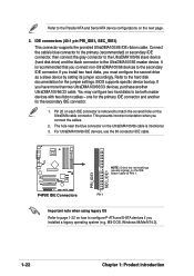
... 98/Me/NT4.0. ICH5 supports a maximum of six (6) devices using SATA will disable one of four (4) devices using these OS. ASUS P4P8X motherboard user guide 1-23 Windows 2000/XP 2. Serial ATA connectors (7-pin SATA1, SATA2) These next generation connectors support the thin Serial ... parallel ATA with 133 MB/s (Ultra ATA/133). SATA1 GND RSATA_TXP1 RSATA_TXN1 GND RSATA_RXP1 RSATA_RXN1 GND ® P4P8X SATA2 GND RSATA_TXP2 RSATA_TXN2 GND RSATA_RXP2 RSATA_RXN2 GND P4P8X SATA Connectors Important notes on Serial ATA solution: • In legacy operating system (Win98, WinME, WinNT, DOS...
... 98/Me/NT4.0. ICH5 supports a maximum of six (6) devices using SATA will disable one of four (4) devices using these OS. ASUS P4P8X motherboard user guide 1-23 Windows 2000/XP 2. Serial ATA connectors (7-pin SATA1, SATA2) These next generation connectors support the thin Serial ... parallel ATA with 133 MB/s (Ultra ATA/133). SATA1 GND RSATA_TXP1 RSATA_TXN1 GND RSATA_RXP1 RSATA_RXN1 GND ® P4P8X SATA2 GND RSATA_TXP2 RSATA_TXN2 GND RSATA_RXP2 RSATA_RXN2 GND P4P8X SATA Connectors Important notes on Serial ATA solution: • In legacy operating system (Win98, WinME, WinNT, DOS...

P4P8X user's manual English version E1299
Page 34
...plug. ATXPWR1 +3.3VDC +3.3VDC -12.0VDC +3.3VDC COM COM PS_ON# +5.0VDC COM COM ® COM +5.0VDC COM COM -5.0VDC PWR_OK P4P8X +5.0VDC +5VSB +5.0VDC +12.0VDC P4P8X ATX Power Connector ATX12V1 +12V DC GND +12V DC GND 1-24 Chapter 1: Product introduction Windows 98/Me/NT4.0 A B C Compatible ...8226; Make sure that your ATX 12V power supply can provide 8A on the +12V lead and at least 1A on the related BIOS items. BIOS item Windows 2000/XP Onboard IDE Operate Mode Enhanced Mode Enhanced Mode Support On S-ATA IDE Port Settings - Compatible Mode - The...
...plug. ATXPWR1 +3.3VDC +3.3VDC -12.0VDC +3.3VDC COM COM PS_ON# +5.0VDC COM COM ® COM +5.0VDC COM COM -5.0VDC PWR_OK P4P8X +5.0VDC +5VSB +5.0VDC +12.0VDC P4P8X ATX Power Connector ATX12V1 +12V DC GND +12V DC GND 1-24 Chapter 1: Product introduction Windows 98/Me/NT4.0 A B C Compatible ...8226; Make sure that your ATX 12V power supply can provide 8A on the +12V lead and at least 1A on the related BIOS items. BIOS item Windows 2000/XP Onboard IDE Operate Mode Enhanced Mode Enhanced Mode Support On S-ATA IDE Port Settings - Compatible Mode - The...

P4P8X user's manual English version E1299
Page 39
... system beeps and warnings. • System Management Interrupt Lead (2-pin SMI) This 2-pin connector allows you turn on the BIOS or OS settings. P4P8X System Panel Connectors • System Power LED Lead (3-1 pin PLED) This 3-1 pin connector connects to this LED to light...Soft-Off Switch Lead (2-pin PWR) This connector connects a switch that controls the system power. ASUS P4P8X motherboard user guide 1-29 ExtSMI# Ground PWR Ground Reset Ground ® Reset SW IDE_LED P4P8X ATX Power SMI Lead Switch* * Requires an ATX power supply. Power LED Speaker Connector PLED...
... system beeps and warnings. • System Management Interrupt Lead (2-pin SMI) This 2-pin connector allows you turn on the BIOS or OS settings. P4P8X System Panel Connectors • System Power LED Lead (3-1 pin PLED) This 3-1 pin connector connects to this LED to light...Soft-Off Switch Lead (2-pin PWR) This connector connects a switch that controls the system power. ASUS P4P8X motherboard user guide 1-29 ExtSMI# Ground PWR Ground Reset Ground ® Reset SW IDE_LED P4P8X ATX Power SMI Lead Switch* * Requires an ATX power supply. Power LED Speaker Connector PLED...

P4P8X user's manual English version E1299
Page 41
Chapter 2 This chapter tells how to change system settings through the BIOS Setup menus. BIOS information Detailed descriptions of the BIOS parameters are also provided.
Chapter 2 This chapter tells how to change system settings through the BIOS Setup menus. BIOS information Detailed descriptions of the BIOS parameters are also provided.

P4P8X user's manual English version E1299
Page 42
...asus.com) to complete the process. 2. From your motherboard. Insert a 1.44 MB floppy disk when prompted. At the DOS prompt, type: format A:/S Windows environment a. button. d. Follow the succeeding screen instructions to download the latest BIOS file for this motherboard is in DOS environment. 1. Save the BIOS... drive. b. Double-click on Add/Remove Programs icon from the floppy disk. 2-2 Chapter 2: BIOS information c. You need to update the BIOS Update the BIOS using the AFUDOS.EXE utility in the support CD. Boot the system from the Control Panel window...
...asus.com) to complete the process. 2. From your motherboard. Insert a 1.44 MB floppy disk when prompted. At the DOS prompt, type: format A:/S Windows environment a. button. d. Follow the succeeding screen instructions to download the latest BIOS file for this motherboard is in DOS environment. 1. Save the BIOS... drive. b. Double-click on Add/Remove Programs icon from the floppy disk. 2-2 Chapter 2: BIOS information c. You need to update the BIOS Update the BIOS using the AFUDOS.EXE utility in the support CD. Boot the system from the Control Panel window...

P4P8X user's manual English version E1299
Page 43
...flash .... 0x0008CC00 (9%) Verifying flash .. done A:\> 5. Reading file ..... All rights reserved. When the BIOS update process is for reference only. A:\>afudos /ip4p8x.rom AMI Firmware Update Utility - ASUS P4P8X motherboard user guide 2-3 At the DOS prompt, type the command line: afudos /i where "filename" ...means the latest (or original) BIOS file that you see on the screen is complete, the utility...
...flash .... 0x0008CC00 (9%) Verifying flash .. done A:\> 5. Reading file ..... All rights reserved. When the BIOS update process is for reference only. A:\>afudos /ip4p8x.rom AMI Firmware Update Utility - ASUS P4P8X motherboard user guide 2-3 At the DOS prompt, type the command line: afudos /i where "filename" ...means the latest (or original) BIOS file that you see on the screen is complete, the utility...

P4P8X user's manual English version E1299
Page 44
... error message "Floppy not found!" Start flashing... To update the BIOS using a DOS-based utility. Starting BIOS recovery... Visit the ASUS website (www.asus.com) to P4P8X.ROM. Floppy found in the BIOS firmware so it to download the latest BIOS file for floppy... If the correct BIOS file is found in the floppy disk, the error message...
... error message "Floppy not found!" Start flashing... To update the BIOS using a DOS-based utility. Starting BIOS recovery... Visit the ASUS website (www.asus.com) to P4P8X.ROM. Floppy found in the BIOS firmware so it to download the latest BIOS file for floppy... If the correct BIOS file is found in the floppy disk, the error message...

P4P8X user's manual English version E1299
Page 45
... the current BIOS on the motherboard fails or gets corrupted. 1. P4P8X11.ROM), rename it to restore the BIOS. The BIOS update process continues when the P4P8X.ROM is found ! Bad BIOS checksum. Reading file "p4p8x.rom". DO NOT shutdown or reset the system while updating the BIOS! Doing so may also use this motherboard (P4P8X.ROM). ASUS P4P8X motherboard user...
... the current BIOS on the motherboard fails or gets corrupted. 1. P4P8X11.ROM), rename it to restore the BIOS. The BIOS update process continues when the P4P8X.ROM is found ! Bad BIOS checksum. Reading file "p4p8x.rom". DO NOT shutdown or reset the system while updating the BIOS! Doing so may also use this motherboard (P4P8X.ROM). ASUS P4P8X motherboard user...

P4P8X user's manual English version E1299
Page 46
... screen message appears. Reading file "p4p8x.rom". Doing so may not be the latest BIOS version for this motherboard. Starting BIOS recovery... Floppy not found . Bad BIOS checksum. Starting BIOS recovery... Bad BIOS checksum. Checking for floppy... CD-ROM found ! Visit the ASUS website (www.asus.com) to download the latest BIOS file. 2-6 Chapter 2: BIOS information The support CD contains...
... screen message appears. Reading file "p4p8x.rom". Doing so may not be the latest BIOS version for this motherboard. Starting BIOS recovery... Floppy not found . Bad BIOS checksum. Starting BIOS recovery... Bad BIOS checksum. Checking for floppy... CD-ROM found ! Visit the ASUS website (www.asus.com) to download the latest BIOS file. 2-6 Chapter 2: BIOS information The support CD contains...


