
P4P8X SE user's manual English version E1479
Page 6
... the correct voltage in any damage, contact your dealer immediately. • To avoid short circuits, keep paper clips, screws, and staples away from connectors, slots, sockets and circuitry. • Avoid dust, humidity, and temperature extremes. Operation safety • Before installing the motherboard and adding devices on a stable surface. • If you...
... the correct voltage in any damage, contact your dealer immediately. • To avoid short circuits, keep paper clips, screws, and staples away from connectors, slots, sockets and circuitry. • Avoid dust, humidity, and temperature extremes. Operation safety • Before installing the motherboard and adding devices on a stable surface. • If you...
P4P8X SE user's manual English version E1479
Page 9
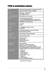
P4P8X SE specifications summary CCPPUU Chipset CFrhoipnst eStide Bus (FSB) FMreomntoSryide Bus (FSB) Memory Expansion slots Expansion slots Storage IDE RAAudIDioIDE / Serial ATA (optional) IGEiEgEab1i3t 9L4AN(optional) USB 2.0 ASpuedcioia(loFpetaiotunrael)s LAN (optional) Overclocking Features Rear Panel I/O Socket 478 for...interface Marvell® 88E8001 Gigabit LAN controller Integrated 8 USB 2.0 ports Power Loss Restart ASUS EZ Flash ASUS CrashFree BIOS 2 ASUS MyLogo2 ASUS JumperFree ASUS C.P.R. (CPU Parameter Recall) Adjustable CPU, memory and AGP voltages SFS (Stepless Frequency Selection...
P4P8X SE specifications summary CCPPUU Chipset CFrhoipnst eStide Bus (FSB) FMreomntoSryide Bus (FSB) Memory Expansion slots Expansion slots Storage IDE RAAudIDioIDE / Serial ATA (optional) IGEiEgEab1i3t 9L4AN(optional) USB 2.0 ASpuedcioia(loFpetaiotunrael)s LAN (optional) Overclocking Features Rear Panel I/O Socket 478 for...interface Marvell® 88E8001 Gigabit LAN controller Integrated 8 USB 2.0 ports Power Loss Restart ASUS EZ Flash ASUS CrashFree BIOS 2 ASUS MyLogo2 ASUS JumperFree ASUS C.P.R. (CPU Parameter Recall) Adjustable CPU, memory and AGP voltages SFS (Stepless Frequency Selection...
P4P8X SE user's manual English version E1479
Page 15
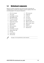
... install the motherboard, learn about its major components and available features to the succeeding pages for the specifications of each component. CPU socket 3. AGP 8X slot 10. Standby power LED 14. PCI slots 15. Line In jack 21. S/PDIF out port 27. Floppy disk ... I/O controller 7. Flash ROM 12. USB 2.0 ports 3 and 4 24. Audio CODEC 16. Refer to facilitate the installation and future upgrades. DDR DIMM sockets 5. ATX 12V connector 2. LAN controller 17. RJ-45 port 20. IDE connectors 9. Microphone jack 23. ASUS P4P8X SE motherboard user guide 1-5
... install the motherboard, learn about its major components and available features to the succeeding pages for the specifications of each component. CPU socket 3. AGP 8X slot 10. Standby power LED 14. PCI slots 15. Line In jack 21. S/PDIF out port 27. Floppy disk ... I/O controller 7. Flash ROM 12. USB 2.0 ports 3 and 4 24. Audio CODEC 16. Refer to facilitate the installation and future upgrades. DDR DIMM sockets 5. ATX 12V connector 2. LAN controller 17. RJ-45 port 20. IDE connectors 9. Microphone jack 23. ASUS P4P8X SE motherboard user guide 1-5
P4P8X SE user's manual English version E1479
Page 17
.... (*Overclocking mode) 3 North bridge controller. This LED acts as a reminder to prevent incorrect insertion of the floppy disk cable. 8 IDE connectors. ASUS P4P8X SE motherboard user guide 1-7 This Accelerated Graphics Port (AGP) slot supports 0.8V/1.5V AGP 8X mode graphics cards for the floppy disk drive. This 4Mb ... before plugging or unplugging devices. This power connector connects the 4-pin 12V plug from the ATX 12V power supply. 2 CPU socket. The Intel® 82865P Memory Controller Hub (MCH) provides the processor interface with 133 MB/s. 11 Flash ROM. These four 184-pin...
.... (*Overclocking mode) 3 North bridge controller. This LED acts as a reminder to prevent incorrect insertion of the floppy disk cable. 8 IDE connectors. ASUS P4P8X SE motherboard user guide 1-7 This Accelerated Graphics Port (AGP) slot supports 0.8V/1.5V AGP 8X mode graphics cards for the floppy disk drive. This 4Mb ... before plugging or unplugging devices. This power connector connects the 4-pin 12V plug from the ATX 12V power supply. 2 CPU socket. The Intel® 82865P Memory Controller Hub (MCH) provides the processor interface with 133 MB/s. 11 Flash ROM. These four 184-pin...

P4P8X SE user's manual English version E1479
Page 19
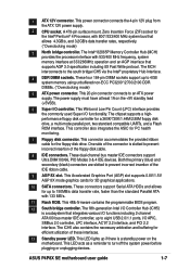
ATX Power Connector FLOPPY1 1.5 Motherboard layout PS/2KBMS KBPWR T: Mouse B: Keyboard SPDIF_O 24.5cm (9.6in) Socket 478 CPU_FAN1 Super I/O DDR DIMM_A1 (64 bit,184-pin module) DDR DIMM_A2 (64 bit,184-pin module) DDR DIMM_B1 (64 bit,184-pin ... Graphics Port (AGP1) Marrell 88E8001 ® CHA_FAN1 CD1 AUX1 Audio Codec FP_AUDIO PCI1 PCI2 PCI3 P4P8X SE PCI4 SATA2 Intel ICH5 SATA1 USBPW56 USBPW78 CLRTC1 USB_56 USB_78 4Mbit Firmware Hub CR2032 3V Lithium Cell CMOS Power PCI5 SB_PWR1 GAME1 CHASSIS1 PANEL1 PRI_IDE1 SEC_IDE1 30.5cm (12.0in) ASUS P4P8X SE motherboard user guide 1-9
ATX Power Connector FLOPPY1 1.5 Motherboard layout PS/2KBMS KBPWR T: Mouse B: Keyboard SPDIF_O 24.5cm (9.6in) Socket 478 CPU_FAN1 Super I/O DDR DIMM_A1 (64 bit,184-pin module) DDR DIMM_A2 (64 bit,184-pin module) DDR DIMM_B1 (64 bit,184-pin ... Graphics Port (AGP1) Marrell 88E8001 ® CHA_FAN1 CD1 AUX1 Audio Codec FP_AUDIO PCI1 PCI2 PCI3 P4P8X SE PCI4 SATA2 Intel ICH5 SATA1 USBPW56 USBPW78 CLRTC1 USB_56 USB_78 4Mbit Firmware Hub CR2032 3V Lithium Cell CMOS Power PCI5 SB_PWR1 GAME1 CHASSIS1 PANEL1 PRI_IDE1 SEC_IDE1 30.5cm (12.0in) ASUS P4P8X SE motherboard user guide 1-9
P4P8X SE user's manual English version E1479
Page 20
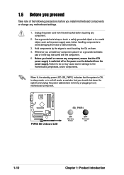
...When lit, the standby power LED (SB_PWR1) indicates that the system is ON, in sleep mode, or in any motherboard component. ® P4P8X SE P4P8X SE Onboard LED SB_PWR1 ON Standby Power OFF Powered Off 1-10 Chapter 1: Product introduction Use a grounded wrist strap or touch a safely grounded object or... power supply. Before you install motherboard components or change any component, ensure that the ATX power supply is detached from the wall socket before you install or remove any motherboard settings. 1. Failure to do so may cause severe damage to static electricity. 3. Hold ...
...When lit, the standby power LED (SB_PWR1) indicates that the system is ON, in sleep mode, or in any motherboard component. ® P4P8X SE P4P8X SE Onboard LED SB_PWR1 ON Standby Power OFF Powered Off 1-10 Chapter 1: Product introduction Use a grounded wrist strap or touch a safely grounded object or... power supply. Before you install motherboard components or change any component, ensure that the ATX power supply is detached from the wall socket before you install or remove any motherboard settings. 1. Failure to do so may cause severe damage to static electricity. 3. Hold ...
P4P8X SE user's manual English version E1479
Page 22
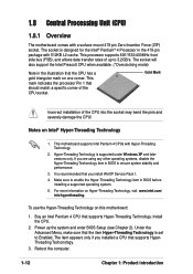
... visit www.intel.com/ info/hyperthreading. This motherboard supports Intel Pentium 4 CPUs with a surface mount 478-pin Zero Insertion Force (ZIF) socket. For more information on this motherboard: 1. Power up to Enabled. It is set to 3.2GB/s. 1.8 Central Processing Unit (CPU) 1.8.1... mark on Intel® Hyper-Threading Technology 1. This mark indicates the processor Pin 1 that supports Hyper-Threading Technology. The socket is supported under Windows XP and later versions only. Notes on one corner. Install the CPU. 2. Reboot the computer. 1-12 Chapter...
... visit www.intel.com/ info/hyperthreading. This motherboard supports Intel Pentium 4 CPUs with a surface mount 478-pin Zero Insertion Force (ZIF) socket. For more information on this motherboard: 1. Power up to Enabled. It is set to 3.2GB/s. 1.8 Central Processing Unit (CPU) 1.8.1... mark on Intel® Hyper-Threading Technology 1. This mark indicates the processor Pin 1 that supports Hyper-Threading Technology. The socket is supported under Windows XP and later versions only. Notes on one corner. Install the CPU. 2. Reboot the computer. 1-12 Chapter...
P4P8X SE user's manual English version E1479
Page 23
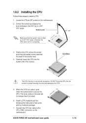
... damaging the CPU! 5. Connect the CPU fan cable to a 90°- 100° angle. Locate the 478-pin ZIF socket on the motherboard. Unlock the socket by pressing the lever sideways, then lift it fits in place. 90 - 100 Gold Mark The CPU fits only in one ... up to the CPU_FAN1 connector on the motherboard. 2. Position the CPU above the socket such that came with the heatsink package. 7. 1.8.2 Installing the CPU Follow these steps to indicate that the socket lever is in completely. 3. ASUS P4P8X SE motherboard user guide 1-13 The lever clicks on the side tab to install a ...
... damaging the CPU! 5. Connect the CPU fan cable to a 90°- 100° angle. Locate the 478-pin ZIF socket on the motherboard. Unlock the socket by pressing the lever sideways, then lift it fits in place. 90 - 100 Gold Mark The CPU fits only in one ... up to the CPU_FAN1 connector on the motherboard. 2. Position the CPU above the socket such that came with the heatsink package. 7. 1.8.2 Installing the CPU Follow these steps to indicate that the socket lever is in completely. 3. ASUS P4P8X SE motherboard user guide 1-13 The lever clicks on the side tab to install a ...
P4P8X SE user's manual English version E1479
Page 24
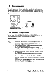
... notes 1. Always install DIMMs with four Double Data Rate (DDR) Dual Inline Memory Module (DIMM) sockets. For optimum compatibility, it is recommended to Table 2. 5. DIMMs installed into any of the DDR DIMM sockets. (*Overclocking mode) SB_PWR1 ® P4P8X SE P4P8X SE Onboard LED ON Standby Power OFF Powered Off 1.9.1 Memory configurations You may install 64MB, 128MB...
... notes 1. Always install DIMMs with four Double Data Rate (DDR) Dual Inline Memory Module (DIMM) sockets. For optimum compatibility, it is recommended to Table 2. 5. DIMMs installed into any of the DDR DIMM sockets. (*Overclocking mode) SB_PWR1 ® P4P8X SE P4P8X SE Onboard LED ON Standby Power OFF Powered Off 1.9.1 Memory configurations You may install 64MB, 128MB...

P4P8X SE user's manual English version E1479
Page 25
...8226; The following FSB/DDR ratios are not supported: 400/333, 400/400, 533/400. Table 1 Recommended memory configurations Mode Single-channel Dual-channel Sockets DIMM_A1 DIMM_A2 DIMM_B1 DIMM_B2 (blue) (black) (blue) (black) (1) Populated - - - (2) - Populated - (4) - - - Populated - ...sockets) and identical DIMMs in DIMM_A2 and DIMM_B2 (black sockets) Table 2 Memory frequency/CPU FSB synchronization This motherboard supports different memory frequencies depending on the CPU FSB (Front Side Bus) and the type of DDR DIMM. Populated - - (3) - - ASUS P4P8X SE...
...8226; The following FSB/DDR ratios are not supported: 400/333, 400/400, 533/400. Table 1 Recommended memory configurations Mode Single-channel Dual-channel Sockets DIMM_A1 DIMM_A2 DIMM_B1 DIMM_B2 (blue) (black) (blue) (black) (1) Populated - - - (2) - Populated - (4) - - - Populated - ...sockets) and identical DIMMs in DIMM_A2 and DIMM_B2 (black sockets) Table 2 Memory frequency/CPU FSB synchronization This motherboard supports different memory frequencies depending on the CPU FSB (Front Side Bus) and the type of DDR DIMM. Populated - - (3) - - ASUS P4P8X SE...

P4P8X SE user's manual English version E1479
Page 26
...) for better system performance. Failure to do so may cause severe damage to install a DIMM. Unlock a DIMM socket by pressing the retaining clips outward. 2. DIMMs 2 2 1 2 2 2 2 2 2 2 2 2 2 2 2 2 2 2 2 2 2 2 2 • Obtain DDR DIMMs only from ASUS qualified vendors for the latest QVL. • FSB800 and DDR400 is properly Unlocked Retaining Clip seated. 1-16 Chapter 1: Product introduction...
...) for better system performance. Failure to do so may cause severe damage to install a DIMM. Unlock a DIMM socket by pressing the retaining clips outward. 2. DIMMs 2 2 1 2 2 2 2 2 2 2 2 2 2 2 2 2 2 2 2 2 2 2 2 • Obtain DDR DIMMs only from ASUS qualified vendors for the latest QVL. • FSB800 and DDR400 is properly Unlocked Retaining Clip seated. 1-16 Chapter 1: Product introduction...


