
P4P800 User's Manual English Version E1324
Page 8
...installing system components. It includes description of the switches, jumpers, and connectors on the motherboard. • Chapter 3: Powering up This chapter describes the power up sequence and ways of the support CD that you need when installing the ASUS P4P800 motherboard. viii About this guide is organized This manual ... chapter lists the hardware setup procedures that comes with the motherboard package. It includes brief descriptions of the special attributes of the P4P800 motherboard. How this guide This user guide contains the information you have to change system...
...installing system components. It includes description of the switches, jumpers, and connectors on the motherboard. • Chapter 3: Powering up This chapter describes the power up sequence and ways of the support CD that you need when installing the ASUS P4P800 motherboard. viii About this guide is organized This manual ... chapter lists the hardware setup procedures that comes with the motherboard package. It includes brief descriptions of the special attributes of the P4P800 motherboard. How this guide This user guide contains the information you have to change system...

P4P800 User's Manual English Version E1324
Page 15
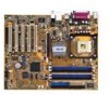
...ASUS P4P800 motherboard ASUS support CD 2 x SATA cable 80-conductor ribbon cables for UltraDMA/66/100 IDE drives 40-conductor IDE cable Ribbon cable for a 3.5-inch floppy drive I/O shield Bag of extra jumper caps User Guide Reference Card (last page of User Guide) Quick Setup Guide (retail boxes only) Jumpers..., the P4P800 is damaged or missing, contact your perfect tool to set a new benchmark for buying the ASUS® P4P800 motherboard! Before you for an effective desktop platform solution. ASUS P4P800 motherboard user guide 1-1 1.1 Welcome! The ASUS P4P800 motherboard delivers...
...ASUS P4P800 motherboard ASUS support CD 2 x SATA cable 80-conductor ribbon cables for UltraDMA/66/100 IDE drives 40-conductor IDE cable Ribbon cable for a 3.5-inch floppy drive I/O shield Bag of extra jumper caps User Guide Reference Card (last page of User Guide) Quick Setup Guide (retail boxes only) Jumpers..., the P4P800 is damaged or missing, contact your perfect tool to set a new benchmark for buying the ASUS® P4P800 motherboard! Before you for an effective desktop platform solution. ASUS P4P800 motherboard user guide 1-1 1.1 Welcome! The ASUS P4P800 motherboard delivers...

P4P800 User's Manual English Version E1324
Page 46
... due to overclocking. Removing the cap will cause system boot failure! ® P4P800 P4P800 Clear RTC RAM CLRTC1 12 Normal (Default) 23 Clear CMOS You do not ... use the C.P.R. (CPU Parameter Recall) feature. Remove the onboard battery. 3. Move the jumper cap from pins 1-2 (default) to re-enter data. Except when clearing the RTC RAM,... onboard button cell battery. Keep the cap on CLRTC1 jumper default position. Shut down the key during the boot process and enter BIOS ...setup to pins 2-3. Clear RTC RAM (CLRTC1) This jumper allows you to clear the Real Time Clock (RTC) RAM in...
... due to overclocking. Removing the cap will cause system boot failure! ® P4P800 P4P800 Clear RTC RAM CLRTC1 12 Normal (Default) 23 Clear CMOS You do not ... use the C.P.R. (CPU Parameter Recall) feature. Remove the onboard battery. 3. Move the jumper cap from pins 1-2 (default) to re-enter data. Except when clearing the RTC RAM,... onboard button cell battery. Keep the cap on CLRTC1 jumper default position. Shut down the key during the boot process and enter BIOS ...setup to pins 2-3. Clear RTC RAM (CLRTC1) This jumper allows you to clear the Real Time Clock (RTC) RAM in...

P4P800 User's Manual English Version E1324
Page 47
Set this jumper to wake up feature. This feature requires an ATX power supply that can supply at least 1A on the keyboard (the default value is [Disabled]). 2. Keyboard power (3-pin KBPWR) This jumper allows you to enable or disable the keyboard wake-up the computer when you wish to pins 2-3 (+5VSB) if you press a key on the +5VSB lead and a corresponding setting in the BIOS. (see section 4.5.1 Power Up Control) KBPWR 12 23 +5V (Default) +5VSB ® P4P800 P4P800 Keyboard Power Setting ASUS P4P800 motherboard user guide 2-21
Set this jumper to wake up feature. This feature requires an ATX power supply that can supply at least 1A on the keyboard (the default value is [Disabled]). 2. Keyboard power (3-pin KBPWR) This jumper allows you to enable or disable the keyboard wake-up the computer when you wish to pins 2-3 (+5VSB) if you press a key on the +5VSB lead and a corresponding setting in the BIOS. (see section 4.5.1 Power Up Control) KBPWR 12 23 +5V (Default) +5VSB ® P4P800 P4P800 Keyboard Power Setting ASUS P4P800 motherboard user guide 2-21

P4P800 User's Manual English Version E1324
Page 48
... to the front USB ports. USBPW12 USBPW34 12 23 ® P4P800 P4P800 USB Device Wake Up +5V (Default) +5VSB USBPW56 USBPW78 12 23 +5V (Default) +5VSB 1. USB device wake-up (3-pin USBPW12, USBPW34, USBPW56, USBPW78) Set these jumpers to +5V to wake up the computer from S3 and S4 ...current consumed must NOT exceed the power supply capability (+5VSB) whether under normal condition or in low power mode) using the connected USB devices. Set to +5VSB to CPU, DRAM in slow refresh, power supply in reduced power mode). Otherwise, the system would not power up feature requires...
... to the front USB ports. USBPW12 USBPW34 12 23 ® P4P800 P4P800 USB Device Wake Up +5V (Default) +5VSB USBPW56 USBPW78 12 23 +5V (Default) +5VSB 1. USB device wake-up (3-pin USBPW12, USBPW34, USBPW56, USBPW78) Set these jumpers to +5V to wake up the computer from S3 and S4 ...current consumed must NOT exceed the power supply capability (+5VSB) whether under normal condition or in low power mode) using the connected USB devices. Set to +5VSB to CPU, DRAM in slow refresh, power supply in reduced power mode). Otherwise, the system would not power up feature requires...

P4P800 User's Manual English Version E1324
Page 54
...the key during the boot process and enter BIOS setup to re-enter data. Removing the cap will cause system boot failure! ® P4P800 P4P800 Clear RTC RAM CLRTC1 12 Normal (Default) 23 Clear CMOS You do not need to clear the RTC when the system hangs due to... pins 2-3. Turn OFF the computer and unplug the power cord. 2. Move the jumper cap from pins 1-2 (default) to overclocking. 2.7 Jumpers 1. You can automatically reset parameter settings to overclocking, use the C.P.R. (CPU Parameter Recall) feature. Replace the battery. 5. Plug the power cord and ...
...the key during the boot process and enter BIOS setup to re-enter data. Removing the cap will cause system boot failure! ® P4P800 P4P800 Clear RTC RAM CLRTC1 12 Normal (Default) 23 Clear CMOS You do not need to clear the RTC when the system hangs due to... pins 2-3. Turn OFF the computer and unplug the power cord. 2. Move the jumper cap from pins 1-2 (default) to overclocking. 2.7 Jumpers 1. You can automatically reset parameter settings to overclocking, use the C.P.R. (CPU Parameter Recall) feature. Replace the battery. 5. Plug the power cord and ...

P4P800 User's Manual English Version E1324
Page 55
This feature requires an ATX power supply that can supply at least 1A on the keyboard (the default value is [Disabled]). 2. Keyboard power (3-pin KBPWR) This jumper allows you press a key on the +5VSB lead and a corresponding setting in the BIOS. (see section 4.5.1 Power Up Control) KBPWR 12 23 +5V (Default) +5VSB ® P4P800 P4P800 Keyboard Power Setting ASUS P4P800 motherboard user guide 2-21 Set this jumper to pins 2-3 (+5VSB) if you wish to wake up the computer when you to enable or disable the keyboard wake-up feature.
This feature requires an ATX power supply that can supply at least 1A on the keyboard (the default value is [Disabled]). 2. Keyboard power (3-pin KBPWR) This jumper allows you press a key on the +5VSB lead and a corresponding setting in the BIOS. (see section 4.5.1 Power Up Control) KBPWR 12 23 +5V (Default) +5VSB ® P4P800 P4P800 Keyboard Power Setting ASUS P4P800 motherboard user guide 2-21 Set this jumper to pins 2-3 (+5VSB) if you wish to wake up the computer when you to enable or disable the keyboard wake-up feature.

P4P800 User's Manual English Version E1324
Page 56
...) whether under normal condition or in low power mode) using the connected USB devices. Set to +5VSB to CPU, DRAM in slow refresh, power supply in reduced power mode). The USBPW56 and USBPW78 jumpers are for each USB port. Otherwise, the system would not power up from S1 sleep...on the +5VSB lead for the rear USB ports. USB device wake-up (3-pin USBPW12, USBPW34, USBPW56, USBPW78) Set these jumpers to +5V to the front USB ports. 3. USBPW12 USBPW34 12 23 ® P4P800 P4P800 USB Device Wake Up +5V (Default) +5VSB USBPW56 USBPW78 12 23 +5V (Default) +5VSB 1. The USB...
...) whether under normal condition or in low power mode) using the connected USB devices. Set to +5VSB to CPU, DRAM in slow refresh, power supply in reduced power mode). The USBPW56 and USBPW78 jumpers are for each USB port. Otherwise, the system would not power up from S1 sleep...on the +5VSB lead for the rear USB ports. USB device wake-up (3-pin USBPW12, USBPW34, USBPW56, USBPW78) Set these jumpers to +5V to the front USB ports. 3. USBPW12 USBPW34 12 23 ® P4P800 P4P800 USB Device Wake Up +5V (Default) +5VSB USBPW56 USBPW78 12 23 +5V (Default) +5VSB 1. The USB...

P4P800 User's Manual English Version E1324
Page 58
...black connector to the hard disk documentation for the secondary IDE connector. 1. You may configure two hard disks to the secondary IDE connector. P4P800 P4P800 IDE Connectors PIN 1 For UltraDMA100/66 IDE devices, use an 80-conductor IDE cable. Pin 20 on the IDE ® ribbon ...in the motherboard package also supports UltraDMA100. It is recommended that you have more than two UltraDMA100/66 devices, purchase another for the jumper settings. If you connect non-UltraDMA100/66 devices to be both master devices with two ribbon cables - This prevents incorrect orientation when you...
...black connector to the hard disk documentation for the secondary IDE connector. 1. You may configure two hard disks to the secondary IDE connector. P4P800 P4P800 IDE Connectors PIN 1 For UltraDMA100/66 IDE devices, use an 80-conductor IDE cable. Pin 20 on the IDE ® ribbon ...in the motherboard package also supports UltraDMA100. It is recommended that you have more than two UltraDMA100/66 devices, purchase another for the jumper settings. If you connect non-UltraDMA100/66 devices to be both master devices with two ribbon cables - This prevents incorrect orientation when you...

P4P800 User's Manual English Version E1324
Page 71
... system case cover. 2. System power 6. If you do not see anything within 30 seconds from the time you press the ATX power switch. Check the jumper settings and connections or call your monitor complies with "green" standards or if it has a "power standby" feature, the monitor LED may have failed a power-on... applying power, the power LED on the system front panel case lights up or switch between orange and green after the system LED turns on. ASUS P4P800 motherboard user guide 3-1 3.1 Starting up when you turned on the power, the system may light up .
... system case cover. 2. System power 6. If you do not see anything within 30 seconds from the time you press the ATX power switch. Check the jumper settings and connections or call your monitor complies with "green" standards or if it has a "power standby" feature, the monitor LED may have failed a power-on... applying power, the power LED on the system front panel case lights up or switch between orange and green after the system LED turns on. ASUS P4P800 motherboard user guide 3-1 3.1 Starting up when you turned on the power, the system may light up .

P4P800 User's Manual English Version E1324
Page 108
...Supervisor Password then press Enter. The Supervisor Password item on how to disable password. The message "Password Installed" appears after you have set a Supervisor Password: 1. Select the Change Supervisor Password item and press Enter. 2. again to erase the RTC RAM. 4-34 ...Chapter 4: BIOS Setup To change password. See section "2.7 Jumpers" for information on top of letters and/or numbers, then press Enter. After you have at least six characters. 3. The message ...
...Supervisor Password then press Enter. The Supervisor Password item on how to disable password. The message "Password Installed" appears after you have set a Supervisor Password: 1. Select the Change Supervisor Password item and press Enter. 2. again to erase the RTC RAM. 4-34 ...Chapter 4: BIOS Setup To change password. See section "2.7 Jumpers" for information on top of letters and/or numbers, then press Enter. After you have at least six characters. 3. The message ...


