
P4P800-X user's manual English version E1718
Page 13
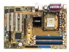
... 30% (depending on USB 2.0. See page 1-15. 10/100 Mbps LAN support Easy connectivity to 150 MB/s data transfer rate, and software compatibility with legacy Parallel ATA. ASUS P4P800-X motherboard 1-3 The Serial ATA specification allows for 5.1 surround sound using digital audio devices via a Sony/Philips Digital Interface (S/PDIF) jack located at the rear panel...
... 30% (depending on USB 2.0. See page 1-15. 10/100 Mbps LAN support Easy connectivity to 150 MB/s data transfer rate, and software compatibility with legacy Parallel ATA. ASUS P4P800-X motherboard 1-3 The Serial ATA specification allows for 5.1 surround sound using digital audio devices via a Sony/Philips Digital Interface (S/PDIF) jack located at the rear panel...
P4P800-X user's manual English version E1718
Page 27
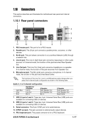
This 25-pin port connects a parallel printer, a scanner, or other audio sources. In 6-channel mode, the function of this jack becomes Rear Speaker Out. 5. In 6-channel mode, the function of this jack becomes Front Speaker ...Serial connector. This 9-pin COM1 port is for connecting USB 2.0 devices. 9. RJ-45 port. This Line In (light blue) jack connects a tape player or other devices. 3. ASUS P4P800-X motherboard 1-17 This port allows connection to external audio output devices. 11. Line Out jack. This Mic (pink) jack connects a microphone. The functions of this jack becomes ...
This 25-pin port connects a parallel printer, a scanner, or other audio sources. In 6-channel mode, the function of this jack becomes Rear Speaker Out. 5. In 6-channel mode, the function of this jack becomes Front Speaker ...Serial connector. This 9-pin COM1 port is for connecting USB 2.0 devices. 9. RJ-45 port. This Line In (light blue) jack connects a tape player or other devices. 3. ASUS P4P800-X motherboard 1-17 This port allows connection to external audio output devices. 11. Line Out jack. This Mic (pink) jack connects a microphone. The functions of this jack becomes ...
P4P800-X user's manual English version E1718
Page 31
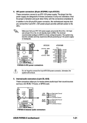
...is inadequate. CD (Black) P4P800-X ® AUX (White) P4P800-X Internal audio connectors Right Audio Channel Ground Ground Left Audio Channel Right Audio Channel Ground Ground Left Audio Channel ASUS P4P800-X motherboard 1-21 ATX power connectors (20-pin ATXPWR, 4-pin ATX12V) These connectors connect to fit these connectors in ... power supply is 300W for a fully configured system. Internal audio connectors (4-pin CD, AUX) These connectors allow you connect the 4-pin ATX +12V power plug to provide sufficient power to connect the 4-pin ATX12V power connector, otherwise, the system will ...
...is inadequate. CD (Black) P4P800-X ® AUX (White) P4P800-X Internal audio connectors Right Audio Channel Ground Ground Left Audio Channel Right Audio Channel Ground Ground Left Audio Channel ASUS P4P800-X motherboard 1-21 ATX power connectors (20-pin ATXPWR, 4-pin ATX12V) These connectors connect to fit these connectors in ... power supply is 300W for a fully configured system. Internal audio connectors (4-pin CD, AUX) These connectors allow you connect the 4-pin ATX +12V power plug to provide sufficient power to connect the 4-pin ATX12V power connector, otherwise, the system will ...
P4P800-X user's manual English version E1718
Page 33
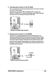
...; P4P800-X Front panel audio connector 9. P4P800-X ® CHASSIS GND Chassis Signal (Default) +5VSB_MB P4P800-X Chassis intrusion connector ASUS P4P800-X motherboard 1-23 Be default, the pins labeled LINE OUT_R/BLINE_OUT_R and the pins LINE OUT_L/BLINE_OUT_L are shorted with a jumper cap. This requires an external detection mechanism such as a chassis intrusion sensor or microswitch. If you are connecting...
...; P4P800-X Front panel audio connector 9. P4P800-X ® CHASSIS GND Chassis Signal (Default) +5VSB_MB P4P800-X Chassis intrusion connector ASUS P4P800-X motherboard 1-23 Be default, the pins labeled LINE OUT_R/BLINE_OUT_R and the pins LINE OUT_L/BLINE_OUT_L are shorted with a jumper cap. This requires an external detection mechanism such as a chassis intrusion sensor or microswitch. If you are connecting...

P4P800-X user's manual English version E1718
Page 34
...5V J1B1 J1CX GND GND J1CY J1B2 +5V P4P800-X ® P4P800-X Game connector GAME The GAME/MIDI module is purchased separately. 1-24 Chapter 1: Product introduction Digital Audio connector (6-1 pin SPDIF_OUT) This connector is available, connect the GAME/MIDI cable to this connector and...other end to allow digital sound output. Connect one end of the S/PDIF audio cable to this connector. GAME/MIDI connector (16-1 pin GAME) This connector supports a GAME/MIDI module. P4P800-X R SPDIF_OUT GND SPDIFOUT +5V P4P800-X Digital audio connector The S/PDIF module is purchased ...
...5V J1B1 J1CX GND GND J1CY J1B2 +5V P4P800-X ® P4P800-X Game connector GAME The GAME/MIDI module is purchased separately. 1-24 Chapter 1: Product introduction Digital Audio connector (6-1 pin SPDIF_OUT) This connector is available, connect the GAME/MIDI cable to this connector and...other end to allow digital sound output. Connect one end of the S/PDIF audio cable to this connector. GAME/MIDI connector (16-1 pin GAME) This connector supports a GAME/MIDI module. P4P800-X R SPDIF_OUT GND SPDIFOUT +5V P4P800-X Digital audio connector The S/PDIF module is purchased ...


