Motherboard DIY Troubleshooting Guide
Page 5
.... Operation is connected. • Consult the dealer or an experienced radio/TV technician for help. Changes or modifications to this unit not expressly approved by turning the equipment off and on a circuit different from digital apparatus set out in a residential installation. v This equipment has been tested and found to comply with...
.... Operation is connected. • Consult the dealer or an experienced radio/TV technician for help. Changes or modifications to this unit not expressly approved by turning the equipment off and on a circuit different from digital apparatus set out in a residential installation. v This equipment has been tested and found to comply with...
Motherboard DIY Troubleshooting Guide
Page 16
... IDE ribbon cable. 9 Flash EEPROM. One side of the floppy disk cable. 8 IDE connectors. Both the primary (blue) and secondary (black) connectors are slotted to turn off the system power before plugging or unplugging devices. 1-6 Chapter 1: Product introduction This LED acts as a reminder to prevent incorrect insertion of these interfaces. 12...
... IDE ribbon cable. 9 Flash EEPROM. One side of the floppy disk cable. 8 IDE connectors. Both the primary (blue) and secondary (black) connectors are slotted to turn off the system power before plugging or unplugging devices. 1-6 Chapter 1: Product introduction This LED acts as a reminder to prevent incorrect insertion of these interfaces. 12...
Motherboard DIY Troubleshooting Guide
Page 26
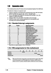
.... Otherwise, conflicts will arise between the two PCI groups, making the system unstable and the card inoperable. 1-16 Chapter 1: Product introduction Refer to the card. Turn on the system and change the necessary BIOS settings, if any. To install and configure an expansion card: 1. 1.10 Expansion slots The motherboard has three...
.... Otherwise, conflicts will arise between the two PCI groups, making the system unstable and the card inoperable. 1-16 Chapter 1: Product introduction Refer to the card. Turn on the system and change the necessary BIOS settings, if any. To install and configure an expansion card: 1. 1.10 Expansion slots The motherboard has three...
Motherboard DIY Troubleshooting Guide
Page 28
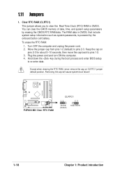
... powered by erasing the CMOS RTC RAM data. Removing the cap will cause system boot failure! To erase the RTC RAM: 1. Turn OFF the computer and unplug the power cord. 2. P4P800-MX ® P4P800-MX Clear RTC RAM CLRTC1 12 23 Normal (Default) Clear CMOS 1-18 Chapter 1: Product introduction The RAM data in CMOS. Clear... date, time, and system setup parameters by the onboard button cell battery. Keep the cap on CLRTC1 jumper default position. Plug the power cord and turn ON the computer. 4. 1.11 Jumpers 1.
... powered by erasing the CMOS RTC RAM data. Removing the cap will cause system boot failure! To erase the RTC RAM: 1. Turn OFF the computer and unplug the power cord. 2. P4P800-MX ® P4P800-MX Clear RTC RAM CLRTC1 12 23 Normal (Default) Clear CMOS 1-18 Chapter 1: Product introduction The RAM data in CMOS. Clear... date, time, and system setup parameters by the onboard button cell battery. Keep the cap on CLRTC1 jumper default position. Plug the power cord and turn ON the computer. 4. 1.11 Jumpers 1.
Motherboard DIY Troubleshooting Guide
Page 38
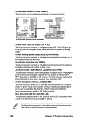
System panel connector (20-pin PANEL1) This connector accommodates several system front panel functions. P4P800-MX System Panel connector • System Power LED Lead (Green 3-pin PLED) This 3-pin connector connects to expand the life of certain system components. The System ... this LED to the hard disk activity LED. The LED lights up . Power LED Speaker Connector PLED+ PLED+5V Ground Ground Speaker P4P800-MX IDE_LED+ IDE_LED- Pressing the power switch turns the system between ON and SLEEP, or ON and SOFT OFF, depending on the system power, and blinks when the system is...
System panel connector (20-pin PANEL1) This connector accommodates several system front panel functions. P4P800-MX System Panel connector • System Power LED Lead (Green 3-pin PLED) This 3-pin connector connects to expand the life of certain system components. The System ... this LED to the hard disk activity LED. The LED lights up . Power LED Speaker Connector PLED+ PLED+5V Ground Ground Speaker P4P800-MX IDE_LED+ IDE_LED- Pressing the power switch turns the system between ON and SLEEP, or ON and SOFT OFF, depending on the system power, and blinks when the system is...

Motherboard DIY Troubleshooting Guide
Page 44
... to the power management settings. Press during the Power-On Self Test (POST) to enter Setup after POST, restart the system by pressing , or by turning the system off and then back on the motherboard stores the Setup utility. If you may want to enable the security password feature or make...
... to the power management settings. Press during the Power-On Self Test (POST) to enter Setup after POST, restart the system by pressing , or by turning the system off and then back on the motherboard stores the Setup utility. If you may want to enable the security password feature or make...
Motherboard DIY Troubleshooting Guide
Page 60
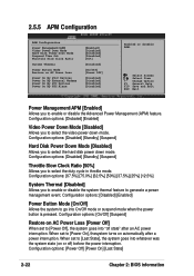
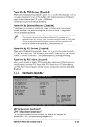
... Select Item +- Configuration options: [Disbaled] [Enabled] Video Power Down Mode [Disabled] Allows you to enable or disable the system thermal feature to [Power On], thesystem turns on automatically after an AC power interruption. Configuration options: [On/Off] [Suspend] Restore on AC Power Loss [Power Off] When set to generate a power management...
... Select Item +- Configuration options: [Disbaled] [Enabled] Video Power Down Mode [Disabled] Allows you to enable or disable the system thermal feature to [Power On], thesystem turns on automatically after an AC power interruption. Configuration options: [On/Off] [Suspend] Restore on AC Power Loss [Power Off] When set to generate a power management...

Motherboard DIY Troubleshooting Guide
Page 61
... transmit data until the computer and applications are fully running. Configuration options: [Disabled] [Enabled] Power On By RTC Alarm [Disabled] Allows you to turn on the system. ASUS P4P800-MX motherboard 2-23 Power On By PCI Devices [Disabled] When set to [Enabled], this parameter allows you to enable or disable RTC to generate a wake...
... transmit data until the computer and applications are fully running. Configuration options: [Disabled] [Enabled] Power On By RTC Alarm [Disabled] Allows you to turn on the system. ASUS P4P800-MX motherboard 2-23 Power On By PCI Devices [Disabled] When set to [Enabled], this parameter allows you to enable or disable RTC to generate a wake...

Motherboard DIY Troubleshooting Guide
Page 67
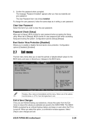
... when accessing Setup and booting the system. The CMOS RAM is sustained by an onboard backup battery and stays on even when the PC is turned off. Exit & Save Changes Once you select this menu. When you are saved to exit. Configuration options: [Setup] [Always] Boot Sector Virus Protection...this menu or from the Exit menu to ensure the values you to [Setup], BIOS checks for the BIOS items, and save changes and exit. ASUS P4P800-MX motherboard 2-29 To change the user password, follow the same steps as in setting a user password. Password Check [Setup] When set to save...
... when accessing Setup and booting the system. The CMOS RAM is sustained by an onboard backup battery and stays on even when the PC is turned off. Exit & Save Changes Once you select this menu. When you are saved to exit. Configuration options: [Setup] [Always] Boot Sector Virus Protection...this menu or from the Exit menu to ensure the values you to [Setup], BIOS checks for the BIOS items, and save changes and exit. ASUS P4P800-MX motherboard 2-29 To change the user password, follow the same steps as in setting a user password. Password Check [Setup] When set to save...

P4P800-MX user's manual
Page 5
... interference by one or more of the following two conditions: • This device may cause harmful interference to operate this unit not expressly approved by turning the equipment off and on a circuit different from digital apparatus set out in a particular installation. This equipment has been tested and found to assure compliance...
... interference by one or more of the following two conditions: • This device may cause harmful interference to operate this unit not expressly approved by turning the equipment off and on a circuit different from digital apparatus set out in a particular installation. This equipment has been tested and found to assure compliance...

P4P800-MX user's manual
Page 16
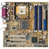
This power connector connects the 4-pin 12V plug from the ATX 12V power supply. 2 CPU socket. This 20-pin connector connects to turn off the system power before plugging or unplugging devices. 1-6 Chapter 1: Product introduction Both the primary (blue) and secondary (black) connectors are slotted to 4GB system ...
This power connector connects the 4-pin 12V plug from the ATX 12V power supply. 2 CPU socket. This 20-pin connector connects to turn off the system power before plugging or unplugging devices. 1-6 Chapter 1: Product introduction Both the primary (blue) and secondary (black) connectors are slotted to 4GB system ...

P4P800-MX user's manual
Page 26
Turn on the next page. 4. Install the drivers and/or software applications for the expansion card according to the card documentation. 1.10.1 Standard interrupt assignments IRQ ...
Turn on the next page. 4. Install the drivers and/or software applications for the expansion card according to the card documentation. 1.10.1 Standard interrupt assignments IRQ ...

P4P800-MX user's manual
Page 28
... boot process and enter BIOS setup to pins 2-3. 1.11 Jumpers 1. Removing the cap will cause system boot failure! Plug the power cord and turn ON the computer. 4. Except when clearing the RTC RAM, never remove the cap on pins 2-3 for about 5~10 seconds, then move the ... 1-2 (default) to re-enter data. Keep the cap on CLRTC1 jumper default position. The RAM data in CMOS. Turn OFF the computer and unplug the power cord. 2. P4P800-MX ® P4P800-MX Clear RTC RAM CLRTC1 12 23 Normal (Default) Clear CMOS 1-18 Chapter 1: Product introduction You can clear the CMOS...
... boot process and enter BIOS setup to pins 2-3. 1.11 Jumpers 1. Removing the cap will cause system boot failure! Plug the power cord and turn ON the computer. 4. Except when clearing the RTC RAM, never remove the cap on pins 2-3 for about 5~10 seconds, then move the ... 1-2 (default) to re-enter data. Keep the cap on CLRTC1 jumper default position. The RAM data in CMOS. Turn OFF the computer and unplug the power cord. 2. P4P800-MX ® P4P800-MX Clear RTC RAM CLRTC1 12 23 Normal (Default) Clear CMOS 1-18 Chapter 1: Product introduction You can clear the CMOS...

P4P800-MX user's manual
Page 38
...IDE_LED ATX Power SMI Lead Switch* * Requires an ATX power supply. Power LED Speaker Connector PLED+ PLED+5V Ground Ground Speaker P4P800-MX IDE_LED+ IDE_LED- P4P800-MX System Panel connector • System Power LED Lead (Green 3-pin PLED) This 3-pin connector connects to light up when you...(20-pin PANEL1) This connector accommodates several system front panel functions. The System Panel connector is color-coded for rebooting the system without turning off the system power. • ATX Power Switch / Soft-Off Switch Lead (Yellow 2-pin PWR ) This connector connects a switch ...
...IDE_LED ATX Power SMI Lead Switch* * Requires an ATX power supply. Power LED Speaker Connector PLED+ PLED+5V Ground Ground Speaker P4P800-MX IDE_LED+ IDE_LED- P4P800-MX System Panel connector • System Power LED Lead (Green 3-pin PLED) This 3-pin connector connects to light up when you...(20-pin PANEL1) This connector accommodates several system front panel functions. The System Panel connector is color-coded for rebooting the system without turning off the system power. • ATX Power Switch / Soft-Off Switch Lead (Yellow 2-pin PWR ) This connector connects a switch ...
P4P800-MX user's manual
Page 44
This section explains how to enter Setup after POST, restart the system by pressing , or by turning the system off and then back on the motherboard stores the Setup utility. If you may want to run this program. For example, you wish ...
This section explains how to enter Setup after POST, restart the system by pressing , or by turning the system off and then back on the motherboard stores the Setup utility. If you may want to run this program. For example, you wish ...

P4P800-MX user's manual
Page 60
... select the duty cycle in throttle mode. Configuration options: [On/Off] [Suspend] Restore on AC Power Loss [Power Off] When set to [Power On], thesystem turns on automatically after an AC power interruption. When set to [Power Off], the system goes into whatever was the system state (on AC Power Loss...
... select the duty cycle in throttle mode. Configuration options: [On/Off] [Suspend] Restore on AC Power Loss [Power Off] When set to [Power On], thesystem turns on automatically after an AC power interruption. When set to [Power Off], the system goes into whatever was the system state (on AC Power Loss...
P4P800-MX user's manual
Page 61
... [xxxC/xxxF] CPU Temperature [xxxC/xxxF] The onboard hardware monitor automatically detects and displays the motherboard, CPU, and power supply temperatures. ASUS P4P800-MX motherboard 2-23 Configuration options: [Disabled] [Enabled] The computer cannot receive or transmit data until the computer and applications are fully running. ...Configuration options: [Disabled] [Enabled] Power On By RTC Alarm [Disabled] Allows you to turn on the +5VSB lead. When this item is set to Enabled, the items RTC Alarm Date, RTC Alarm Hour, RTC Alarm...
... [xxxC/xxxF] CPU Temperature [xxxC/xxxF] The onboard hardware monitor automatically detects and displays the motherboard, CPU, and power supply temperatures. ASUS P4P800-MX motherboard 2-23 Configuration options: [Disabled] [Enabled] The computer cannot receive or transmit data until the computer and applications are fully running. ...Configuration options: [Disabled] [Enabled] Power On By RTC Alarm [Disabled] Allows you to turn on the +5VSB lead. When this item is set to Enabled, the items RTC Alarm Date, RTC Alarm Hour, RTC Alarm...
P4P800-MX user's manual
Page 67
... PC is turned off. Exit & Save Changes Once you selected are finished making your password. When you wish to the CMOS RAM. Select [Yes] to exit. Confirm the password when prompted. 3. Configuration options: [Setup] [Always] Boot Sector Virus Protection [Disabled] Allows you have successfully set your selections, choose this menu. ASUS P4P800-MX motherboard...
... PC is turned off. Exit & Save Changes Once you selected are finished making your password. When you wish to the CMOS RAM. Select [Yes] to exit. Confirm the password when prompted. 3. Configuration options: [Setup] [Always] Boot Sector Virus Protection [Disabled] Allows you have successfully set your selections, choose this menu. ASUS P4P800-MX motherboard...


