
P4B266 User Manaul
Page 4
... Chapter 3: Powering up 3-1 3.1 Starting up for the first time 3-1 3.2 Vocal POST Messages 3-2 3.3 Powering off the computer 3-4 Chapter 4: BIOS setup 4-1 4.1 Managing and updating your BIOS 4-1 4.1.1 Using the computer system for the first time 4-1 4.1.2 Updating BIOS procedures 4-3 4.2 BIOS Setup program 4-5 4.2.1 BIOS menu bar 4-6 4.2.2 Legend bar 4-6 4.3 Main Menu 4-8 4.3.1 Primary and Secondary Master/Slave 4-9 4.3.2 Keyboard Features 4-13 4.4 Advanced Menu...
... Chapter 3: Powering up 3-1 3.1 Starting up for the first time 3-1 3.2 Vocal POST Messages 3-2 3.3 Powering off the computer 3-4 Chapter 4: BIOS setup 4-1 4.1 Managing and updating your BIOS 4-1 4.1.1 Using the computer system for the first time 4-1 4.1.2 Updating BIOS procedures 4-3 4.2 BIOS Setup program 4-5 4.2.1 BIOS menu bar 4-6 4.2.2 Legend bar 4-6 4.3 Main Menu 4-8 4.3.1 Primary and Secondary Master/Slave 4-9 4.3.2 Keyboard Features 4-13 4.4 Advanced Menu...

P4B266 User Manaul
Page 8
... This chapter describes the power up sequence and gives information on the BIOS beep codes. • Chapter 4: BIOS setup This chapter tells how to perform when installing system components. Detailed descriptions of the BIOS parameters are also provided. • Chapter 5: Software support This chapter...through the BIOS Setup menus. It includes brief descriptions of the special attributes of the motherboard and the new technology it supports. • Chapter 2: Hardware information This chapter lists the hardware setup procedures that you need when installing the ASUS P4B266 motherboard. ...
... This chapter describes the power up sequence and gives information on the BIOS beep codes. • Chapter 4: BIOS setup This chapter tells how to perform when installing system components. Detailed descriptions of the BIOS parameters are also provided. • Chapter 5: Software support This chapter...through the BIOS Setup menus. It includes brief descriptions of the special attributes of the motherboard and the new technology it supports. • Chapter 2: Hardware information This chapter lists the hardware setup procedures that you need when installing the ASUS P4B266 motherboard. ...

P4B266 User Manaul
Page 15
...supports coaxial interfaces. ASUS P4B266 motherboard user guide 1-3 The SD/MS Reader allows portable high-capacity storage through BIOS built-in optimization mode • adjustable CPU VCORE and DDR memory voltage ASUS iPanel support The motherboard supports the ASUS iPanel to page ...and convenient monitoring of system status. See page 2-33. 1.3.2 Value-added solutions Overclocking The P4B266 overclocking features: • adjustable CPU frequency multiple in BIOS using the ASUS JumperFree™ solution • adjustable FSB/PCI frequency ratio • Stepless Frequency Selection ...
...supports coaxial interfaces. ASUS P4B266 motherboard user guide 1-3 The SD/MS Reader allows portable high-capacity storage through BIOS built-in optimization mode • adjustable CPU VCORE and DDR memory voltage ASUS iPanel support The motherboard supports the ASUS iPanel to page ...and convenient monitoring of system status. See page 2-33. 1.3.2 Value-added solutions Overclocking The P4B266 overclocking features: • adjustable CPU frequency multiple in BIOS using the ASUS JumperFree™ solution • adjustable FSB/PCI frequency ratio • Stepless Frequency Selection ...

P4B266 User Manaul
Page 19
... BIOS program. 14 South bridge controller. This controller supports the Universal Serial Bus (USB) 2.0 specification for a fast connection speed of up if there is specifically designed for PC peripherals. (optional) 17 Onboard LED. This slot is a standby power on audio models only) ASUS P4B266 ...In (0.5~5V) and S/PDIF Out (44.1K and 48K formats) professional digital audio interface. (on the motherboard. This Winbond speech controller supports ASUS POST Reporter™ for a 360K/720K/1.44M/ 2.88M floppy disk drive, a multi-mode parallel port, two standard compatible UARTs, a Standard ...
... BIOS program. 14 South bridge controller. This controller supports the Universal Serial Bus (USB) 2.0 specification for a fast connection speed of up if there is specifically designed for PC peripherals. (optional) 17 Onboard LED. This slot is a standby power on audio models only) ASUS P4B266 ...In (0.5~5V) and S/PDIF Out (44.1K and 48K formats) professional digital audio interface. (on the motherboard. This Winbond speech controller supports ASUS POST Reporter™ for a 360K/720K/1.44M/ 2.88M floppy disk drive, a multi-mode parallel port, two standard compatible UARTs, a Standard ...

P4B266 User Manaul
Page 35
...motherboard components. 2.6.1 Installing an expansion card Follow these steps to install an expansion card. 1. See Chapter 4 for the expansion card. ASUS P4B266 motherboard user guide 2-13 Failure to do so may cause you may need to the card. Keep the screw for the card. 2..... 2.6.2 Configuring an expansion card After physically installing the expansion card, configure the card by adjusting the software settings. 1. Turn on BIOS setup. 2. Before installing the expansion card, read the documentation that they support. The following subsections describe the slots and the expansion ...
...motherboard components. 2.6.1 Installing an expansion card Follow these steps to install an expansion card. 1. See Chapter 4 for the expansion card. ASUS P4B266 motherboard user guide 2-13 Failure to do so may cause you may need to the card. Keep the screw for the card. 2..... 2.6.2 Configuring an expansion card After physically installing the expansion card, configure the card by adjusting the software settings. 1. Turn on BIOS setup. 2. Before installing the expansion card, read the documentation that they support. The following subsections describe the slots and the expansion ...

P4B266 User Manaul
Page 39
... 4. JEN SWITCH ® ON 1 2 3 4 5 6 7 8 9 10 ON OFF P4B266 12 Jumper Mode P4B266 JumperFree™ Mode Setting 23 Jumper Free (Default) The JEN jumper is adjusted through the BIOS setup instead of using the DIP switches. Frequency Multiple 2. Otherwise, setting the switches does not produce...8482; mode (JEN) This jumper allows you to use the DIP switches. ASUS P4B266 motherboard user guide 2-17 The white block represents the switch position. Frequency Selection 9. Reserved ON ON P4B266 DIP Switches The JEN jumper must be set all the switches in conjunction with ...
... 4. JEN SWITCH ® ON 1 2 3 4 5 6 7 8 9 10 ON OFF P4B266 12 Jumper Mode P4B266 JumperFree™ Mode Setting 23 Jumper Free (Default) The JEN jumper is adjusted through the BIOS setup instead of using the DIP switches. Frequency Multiple 2. Otherwise, setting the switches does not produce...8482; mode (JEN) This jumper allows you to use the DIP switches. ASUS P4B266 motherboard user guide 2-17 The white block represents the switch position. Frequency Selection 9. Reserved ON ON P4B266 DIP Switches The JEN jumper must be set all the switches in conjunction with ...

P4B266 User Manaul
Page 42
... ATX power supply that you press a key on the +5VSB lead, and a corresponding setting in the BIOS (see section 4.5.1 Power Up Control). ® P4B266 KBPWR 2 1 +5V (Default) 3 2 +5VSB P4B266 Keyboard Power Setting 5. Set this jumper to pins 2-3 (+5VSB) if you wish to enable or disable ... you to wake up feature. Setting to the system memory by changing the jumper setting. 4. DDR_OV ® P4B266 12 DISABLE (Default) 23 34 STAGE1 STAGE2 P4B266 DDR_OV Setting 2-20 Chapter 2: Hardware information Keyboard power (3-pin KBPWR) This jumper allows you to select the voltage...
... ATX power supply that you press a key on the +5VSB lead, and a corresponding setting in the BIOS (see section 4.5.1 Power Up Control). ® P4B266 KBPWR 2 1 +5V (Default) 3 2 +5VSB P4B266 Keyboard Power Setting 5. Set this jumper to pins 2-3 (+5VSB) if you wish to enable or disable ... you to wake up feature. Setting to the system memory by changing the jumper setting. 4. DDR_OV ® P4B266 12 DISABLE (Default) 23 34 STAGE1 STAGE2 P4B266 DDR_OV Setting 2-20 Chapter 2: Hardware information Keyboard power (3-pin KBPWR) This jumper allows you to select the voltage...

P4B266 User Manaul
Page 44
Setting to a very high core voltage may cause permanent damage to 1.75V range for the ASUS POST Reporter™ function. When disabled, the allowed Vcore settings are lower. It is recommended that you connected an external ...) 8. Set to pins 1-2 to pins 2-3 if you keep the default setting (Disable). ® P4B266 OVER_VOLT 2 1 DISABLE (Default) 3 2 ENABLE P4B266 OVER_VOLT Setting 2-22 Chapter 2: Hardware information Set to use for Northwood processor through BIOS Setup. VCORE over-voltage (3-pin OVER_VOLT) When enabled, this jumper allows a CPU Vcore setting range of...
Setting to a very high core voltage may cause permanent damage to 1.75V range for the ASUS POST Reporter™ function. When disabled, the allowed Vcore settings are lower. It is recommended that you connected an external ...) 8. Set to pins 1-2 to pins 2-3 if you keep the default setting (Disable). ® P4B266 OVER_VOLT 2 1 DISABLE (Default) 3 2 ENABLE P4B266 OVER_VOLT Setting 2-22 Chapter 2: Hardware information Set to use for Northwood processor through BIOS Setup. VCORE over-voltage (3-pin OVER_VOLT) When enabled, this jumper allows a CPU Vcore setting range of...

P4B266 User Manaul
Page 46
... RAM data in CMOS. Short the solder points. 4. 11. Remove the battery. 3. Hold down the key during the boot process and enter BIOS setup to re-enter data. ® P4B266 P4B266 Clear RTC RAM CR2032 3V Lithium Cell CMOS Power CLRTC(R197) Short solder points to enable or disable the Universal Serial Bus... the power cord and turn ON the computer. 6. To erase the RTC RAM: 1. Set to Enable (pins 1-2) if you to use USB 2.0 compliant devices. ® P4B266 P4B266 USB Setting USB20_EN 32 21 Disable Enable (Default) 12.
... RAM data in CMOS. Short the solder points. 4. 11. Remove the battery. 3. Hold down the key during the boot process and enter BIOS setup to re-enter data. ® P4B266 P4B266 Clear RTC RAM CR2032 3V Lithium Cell CMOS Power CLRTC(R197) Short solder points to enable or disable the Universal Serial Bus... the power cord and turn ON the computer. 6. To erase the RTC RAM: 1. Set to Enable (pins 1-2) if you to use USB 2.0 compliant devices. ® P4B266 P4B266 USB Setting USB20_EN 32 21 Disable Enable (Default) 12.

P4B266 User Manaul
Page 48
...disk documentation for the primary IDE connector and another UltraDMA/100/66 cable. P4B266 IDE Connectors PIN 1 For UltraDMA/100/66 IDE devices, use an 80-conductor IDE cable. 2. Refer to PIN 1. BIOS supports specific device bootup. one for the jumper settings. Secondary IDE Connector ...Primary IDE Connector ® P4B266 NOTE: Orient the red markings (usually zigzag) on each IDE connector is removed to be...
...disk documentation for the primary IDE connector and another UltraDMA/100/66 cable. P4B266 IDE Connectors PIN 1 For UltraDMA/100/66 IDE devices, use an 80-conductor IDE cable. 2. Refer to PIN 1. BIOS supports specific device bootup. one for the jumper settings. Secondary IDE Connector ...Primary IDE Connector ® P4B266 NOTE: Orient the red markings (usually zigzag) on each IDE connector is removed to be...

P4B266 User Manaul
Page 57
... support this connector. Use the five pins as shown in BIOS to the pin definitions. ® P4B266 IR 1 P4B266 Infrared Module Connector +5V (NC) IRRX GND IRTX Front View Back View IRTX +5V GND (NC) IRRX 17. Ground TRPWR ® P4B266 P4B266 Power Supply Thermal Connector ASUS P4B266 motherboard user guide 2-35 You must also configure the...
... support this connector. Use the five pins as shown in BIOS to the pin definitions. ® P4B266 IR 1 P4B266 Infrared Module Connector +5V (NC) IRRX GND IRTX Front View Back View IRTX +5V GND (NC) IRRX 17. Ground TRPWR ® P4B266 P4B266 Power Supply Thermal Connector ASUS P4B266 motherboard user guide 2-35 You must also configure the...

P4B266 User Manaul
Page 59
Pressing the power switch turns the system between ON and SLEEP, or ON and SOFT OFF, depending on the BIOS or OS settings. ASUS P4B266 motherboard user guide 2-37 • ATX Power Switch / Soft-Off Switch Lead (2-pin PWRBTN) This connector connects a switch that controls the system power. Pressing the power switch while in the ON mode for more than 4 seconds turns the system OFF. • Reset Switch Lead (2-pin RESET) This 2-pin connector connects to the case-mounted reset switch for rebooting the system without turning off the system power.
Pressing the power switch turns the system between ON and SLEEP, or ON and SOFT OFF, depending on the BIOS or OS settings. ASUS P4B266 motherboard user guide 2-37 • ATX Power Switch / Soft-Off Switch Lead (2-pin PWRBTN) This connector connects a switch that controls the system power. Pressing the power switch while in the ON mode for more than 4 seconds turns the system OFF. • Reset Switch Lead (2-pin RESET) This 2-pin connector connects to the case-mounted reset switch for rebooting the system without turning off the system power.

P4B266 User Manaul
Page 61
Chapter 3 This chapter describes the power up Powering up sequence and gives information on the BIOS beep codes.
Chapter 3 This chapter describes the power up Powering up sequence and gives information on the BIOS beep codes.

P4B266 User Manaul
Page 63
... all switches are running at the back of the chassis). 6. You will not hear the BIOS beeps when the ASUS POST Reporter™ is equipped with a surge protector. 5. System running , the BIOS beeps or additional messages appear on the devices in the following order: a. After applying power,...the system LED lights up or switch between orange and green after the system LED turns on the chain) c. ASUS P4B266 motherboard user guide 3-1 Connect the power cord to enter BIOS Setup. Turn on the screen. Monitor b. If your retailer for the first time 1. Check the jumper settings...
... all switches are running at the back of the chassis). 6. You will not hear the BIOS beeps when the ASUS POST Reporter™ is equipped with a surge protector. 5. System running , the BIOS beeps or additional messages appear on the devices in the following order: a. After applying power,...the system LED lights up or switch between orange and green after the system LED turns on the chain) c. ASUS P4B266 motherboard user guide 3-1 Connect the power cord to enter BIOS Setup. Turn on the screen. Monitor b. If your retailer for the first time 1. Check the jumper settings...
P4B266 User Manaul
Page 64
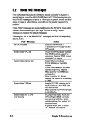
...section "2.3 System memory" for assistance. See section "4.4 Advanced menu." • In jumper mode, refer to support a special feature called the ASUS POST Reporter™. These POST messages are not defective. • Refer to inform you only set to replace the default messages. System failed CPU...on installing a DIMM. See the "ASUS contact information" on the DIMM sockets are properly installed. • Make sure that your DIMMs are customizable using the Winbond Voice Editor software that your package. You can record your CPU settings in BIOS and make sure you of the problem...
...section "2.3 System memory" for assistance. See section "4.4 Advanced menu." • In jumper mode, refer to support a special feature called the ASUS POST Reporter™. These POST messages are not defective. • Refer to inform you only set to replace the default messages. System failed CPU...on installing a DIMM. See the "ASUS contact information" on the DIMM sockets are properly installed. • Make sure that your DIMMs are customizable using the Winbond Voice Editor software that your package. You can record your CPU settings in BIOS and make sure you of the problem...

P4B266 User Manaul
Page 65
ASUS P4B266 motherboard user guide 3-3 No IDE hard disk detected • Make sure you have connected a floppy disk to the one of the IDE connectors on page x. See the "ASUS contact information" on the motherboard. • See section "2.8 Connectors." See section "4.4.2 I/O Device Configuration". System ... • No action required Computer now booting from operating • No action required system You may disable the ASUS POST Reporter™ in the BIOS setup. No floppy disk detected • Make sure you applied power to the purple PS/2 connector on the ...
ASUS P4B266 motherboard user guide 3-3 No IDE hard disk detected • Make sure you have connected a floppy disk to the one of the IDE connectors on page x. See the "ASUS contact information" on the motherboard. • See section "2.8 Connectors." See section "4.4.2 I/O Device Configuration". System ... • No action required Computer now booting from operating • No action required system You may disable the ASUS POST Reporter™ in the BIOS setup. No floppy disk detected • Make sure you applied power to the purple PS/2 connector on the ...

P4B266 User Manaul
Page 67
Chapter 4 This chapter tells how to change system settings through the BIOS Setup menus. BIOS setup Detailed descriptions of the BIOS parameters are also provided.
Chapter 4 This chapter tells how to change system settings through the BIOS Setup menus. BIOS setup Detailed descriptions of the BIOS parameters are also provided.

P4B266 User Manaul
Page 69
...programmed by uploading a new BIOS file to the programmable flash ROM on the upper left-hand corner of your CD-ROM drive) to copy AFLASH.EXE to reinstall the BIOS later. BIOS setup must specify "Floppy" as the first item in DOS mode. ASUS P4B266 motherboard user guide 4-1 ...Larger numbers represent a newer BIOS file. 1. Type COPY D:\AFLASH\AFLASH.EXE A:\ (assuming D is recommended ...
...programmed by uploading a new BIOS file to the programmable flash ROM on the upper left-hand corner of your CD-ROM drive) to copy AFLASH.EXE to reinstall the BIOS later. BIOS setup must specify "Floppy" as the first item in DOS mode. ASUS P4B266 motherboard user guide 4-1 ...Larger numbers represent a newer BIOS file. 1. Type COPY D:\AFLASH\AFLASH.EXE A:\ (assuming D is recommended ...

P4B266 User Manaul
Page 70
The Save Current BIOS To File screen appears. 6. Select 1. Save Current BIOS to File from the Main menu and press . Type a filename and the path, for example, A:\XXX-XX.XXX, then press . 4-2 Chapter 4: BIOS Setup 5.
The Save Current BIOS To File screen appears. 6. Select 1. Save Current BIOS to File from the Main menu and press . Type a filename and the path, for example, A:\XXX-XX.XXX, then press . 4-2 Chapter 4: BIOS Setup 5.

P4B266 User Manaul
Page 71
... with the motherboard and you are sure that the new BIOS revision will solve your new BIOS and the path, for details) and save to start the update. ASUS P4B266 motherboard user guide 4-3 At the Main Menu, type 2 then press . 4.1.2 Updating BIOS procedures Update the BIOS only if you have problems with the motherboard! 1. To cancel...
... with the motherboard and you are sure that the new BIOS revision will solve your new BIOS and the path, for details) and save to start the update. ASUS P4B266 motherboard user guide 4-3 At the Main Menu, type 2 then press . 4.1.2 Updating BIOS procedures Update the BIOS only if you have problems with the motherboard! 1. To cancel...


