
Motherboard DIY Troubleshooting Guide
Page 13
... devices on it another standout in the world of ASUS quality motherboards! The ASUS P4B-M motherboard delivers a host of the above items is your retailer. ASUS P4B-M motherboard user guide 1-1 Supporting up to 3GB of system memory with the list below. 1.2 Package contents Check your P4B-M package for the following items. ASUS P4B-M motherboard (micro-ATX form factor: 9.6-in x 9.6-in your package with...
... devices on it another standout in the world of ASUS quality motherboards! The ASUS P4B-M motherboard delivers a host of the above items is your retailer. ASUS P4B-M motherboard user guide 1-1 Supporting up to 3GB of system memory with the list below. 1.2 Package contents Check your P4B-M package for the following items. ASUS P4B-M motherboard (micro-ATX form factor: 9.6-in x 9.6-in your package with...
Motherboard DIY Troubleshooting Guide
Page 15
...Package (DIP) allows you to an ATX 12V power supply. A 478-pin surface mount, Zero Insertion Force (ZIF) socket called the Intel Memory Controller Hub (MCH) is slotted to 3GB using unbuffered ECC or non-ECC PC100/133 SDRAM DIMMs. 4 ATX power connector. This socket accommodates... one MPU-401 UART mode compatible MIDI/game port, and a Flash ROM interface. 6 IDE connectors. 1 CPU socket. ASUS P4B-M motherboard user guide 1-3 The MCH provides the processor interface, system memory interface, AGP interface, and Hub Interface. 3 SDRAM DIMM sockets. The power supply must have at least 1A on the ...
...Package (DIP) allows you to an ATX 12V power supply. A 478-pin surface mount, Zero Insertion Force (ZIF) socket called the Intel Memory Controller Hub (MCH) is slotted to 3GB using unbuffered ECC or non-ECC PC100/133 SDRAM DIMMs. 4 ATX power connector. This socket accommodates... one MPU-401 UART mode compatible MIDI/game port, and a Flash ROM interface. 6 IDE connectors. 1 CPU socket. ASUS P4B-M motherboard user guide 1-3 The MCH provides the processor interface, system memory interface, AGP interface, and Hub Interface. 3 SDRAM DIMM sockets. The power supply must have at least 1A on the ...

Motherboard DIY Troubleshooting Guide
Page 22
...GAME_AUDIO Realtek RTL8100 COM2 ATX12V Line Out Line In SYSTEM_FAN Mic In Intel 845 Memory Controller Hub (MCH) 01 23 45 Accelerated Graphics Port (AGP) SERIRQ_CON P4B-M LAN_EN BCS1 BCS2 AUX INT_LINEIN CD MIC HPHONE SPDIF_C PCI1 PCI2 ® ...CR2032 3V Lithium Cell CMOS Power Intel I/O Controller Hub (ICH2) CLEAR CMOS 2Mbit Firmware Hub BUZZER MODEM C-Media CMI8738 6CH Audio Controller PCI3 CNR_SLOT LED1 ASUS ASIC USBPWR23 CNRUSB0 CNRUSB1 USB23 HDDLED PANEL DIP_SW Figure 2-2 Motherboard...
...GAME_AUDIO Realtek RTL8100 COM2 ATX12V Line Out Line In SYSTEM_FAN Mic In Intel 845 Memory Controller Hub (MCH) 01 23 45 Accelerated Graphics Port (AGP) SERIRQ_CON P4B-M LAN_EN BCS1 BCS2 AUX INT_LINEIN CD MIC HPHONE SPDIF_C PCI1 PCI2 ® ...CR2032 3V Lithium Cell CMOS Power Intel I/O Controller Hub (ICH2) CLEAR CMOS 2Mbit Firmware Hub BUZZER MODEM C-Media CMI8738 6CH Audio Controller PCI3 CNR_SLOT LED1 ASUS ASIC USBPWR23 CNRUSB0 CNRUSB1 USB23 HDDLED PANEL DIP_SW Figure 2-2 Motherboard...

Motherboard DIY Troubleshooting Guide
Page 30
...sockets support up to avoid damaging the DIMM. 2.5.2 Memory configurations Install DIMMs in only one direction. 2.5 System memor y 2.5.1 Overview The motherboard comes with notches so that they fit in any of the following combinations. DIMM Location 168-pin DIMM (SDR) Total Memory Socket 1 (Rows 0&1) 64MB, 128MB, 256MB, 512MB...= 2-10 Chapter 2: Hardware information DO NOT force a DIMM into a socket to 3GB system memory using unbuffered ECC or non-ECC PC100/133 DIMMs. 88 Pins P4B-M ® P4B-M 168-Pin DIMM Sockets 60 Pins 20 Pins Figure 2-13 DIMM Sockets Location and SDR DIMMs ...
...sockets support up to avoid damaging the DIMM. 2.5.2 Memory configurations Install DIMMs in only one direction. 2.5 System memor y 2.5.1 Overview The motherboard comes with notches so that they fit in any of the following combinations. DIMM Location 168-pin DIMM (SDR) Total Memory Socket 1 (Rows 0&1) 64MB, 128MB, 256MB, 512MB...= 2-10 Chapter 2: Hardware information DO NOT force a DIMM into a socket to 3GB system memory using unbuffered ECC or non-ECC PC100/133 DIMMs. 88 Pins P4B-M ® P4B-M 168-Pin DIMM Sockets 60 Pins 20 Pins Figure 2-13 DIMM Sockets Location and SDR DIMMs ...

Motherboard DIY Troubleshooting Guide
Page 41
You can clear the CMOS memory of date, time, and system setup parameters by the onboard button cell battery. Turn OFF the computer and unplug the power cord. 2. Plug the power cord and turn ON the computer. 6. P4B-M ® P4B-M Clear RTC RAM Figure 2-28 Clear RTC RAM Intel I/O Controller Hub...RAM: 1. Remove the battery. 3. Re-install the battery. 5. Hold down the key during the boot process and enter BIOS setup to clear CMOS ASUS P4B-M motherboard user guide 2-21 6. Clear RTC RAM (CLRCMOS) These pads allow you to clear the Real Time Clock (RTC) RAM in CMOS, that include ...
You can clear the CMOS memory of date, time, and system setup parameters by the onboard button cell battery. Turn OFF the computer and unplug the power cord. 2. Plug the power cord and turn ON the computer. 6. P4B-M ® P4B-M Clear RTC RAM Figure 2-28 Clear RTC RAM Intel I/O Controller Hub...RAM: 1. Remove the battery. 3. Re-install the battery. 5. Hold down the key during the boot process and enter BIOS setup to clear CMOS ASUS P4B-M motherboard user guide 2-21 6. Clear RTC RAM (CLRCMOS) These pads allow you to clear the Real Time Clock (RTC) RAM in CMOS, that include ...
Motherboard DIY Troubleshooting Guide
Page 55
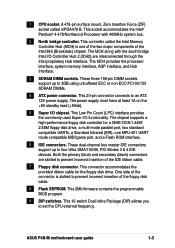
... on the chain) c. Be sure that is working Meaning No error during POST No DRAM installed or detected Video card not found or video card memory bad CPU overheated; Monitor b. External SCSI devices (starting with a surge protector. 5. System power (if you are running at the back of the chassis). 6....or additional messages appear on the screen. If you do not see anything within 30 seconds from the time you need to enter BIOS Setup. ASUS P4B-M motherboard user guide 3-1 3.1 Star ting up or switch between orange and green after the system LED turns on. Connect the power cord to the ...
... on the chain) c. Be sure that is working Meaning No error during POST No DRAM installed or detected Video card not found or video card memory bad CPU overheated; Monitor b. External SCSI devices (starting with a surge protector. 5. System power (if you are running at the back of the chassis). 6....or additional messages appear on the screen. If you do not see anything within 30 seconds from the time you need to enter BIOS Setup. ASUS P4B-M motherboard user guide 3-1 3.1 Star ting up or switch between orange and green after the system LED turns on. Connect the power cord to the ...
Motherboard DIY Troubleshooting Guide
Page 59
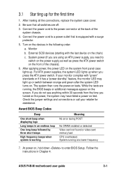
... CONFIG.SYS to run AFLASH. It is your motherboard, check the last four numbers of the code displayed on the motherboard. If the word "unknown" appears after Flash Memory:, the memory chip is either not programmable or is a Flash Memory Writer utility that you created. This file works...on the upper left-hand corner of the original motherboard BIOS along with certain memory drivers that may be programmed by the Flash Memory Writer utility. Type FORMAT A:/S at the DOS prompt to a bootable floppy disk in DOS mode. ASUS P4B-M motherboard user guide 4-1 AFLASH works only in case ...
... CONFIG.SYS to run AFLASH. It is your motherboard, check the last four numbers of the code displayed on the motherboard. If the word "unknown" appears after Flash Memory:, the memory chip is either not programmable or is a Flash Memory Writer utility that you created. This file works...on the upper left-hand corner of the original motherboard BIOS along with certain memory drivers that may be programmed by the Flash Memory Writer utility. Type FORMAT A:/S at the DOS prompt to a bootable floppy disk in DOS mode. ASUS P4B-M motherboard user guide 4-1 AFLASH works only in case ...

Motherboard DIY Troubleshooting Guide
Page 73
... CPU Level 1 and Level 2 built-in the popup menu vary according to the system bus and PCI bus. CPU/Memory Frequency Ratio [Auto] This field determines whether the memory clock frequency is locked, you to choose from the default of [Enabled] or choose [Disabled] to the system frequency....Configuration options: [Auto] [1:1] [3:4] CPU Level 1 Cache, CPU Level 2 Cache [Enabled] These fields allow you cannot access this field. Configuration options: [Disabled] [Enabled] ASUS P4B-M motherboard user guide 4-15 4.4 Advanced Menu CPU Speed This parameter displays the auto-detected CPU speed.
... CPU Level 1 and Level 2 built-in the popup menu vary according to the system bus and PCI bus. CPU/Memory Frequency Ratio [Auto] This field determines whether the memory clock frequency is locked, you to choose from the default of [Enabled] or choose [Disabled] to the system frequency....Configuration options: [Auto] [1:1] [3:4] CPU Level 1 Cache, CPU Level 2 Cache [Enabled] These fields allow you cannot access this field. Configuration options: [Disabled] [Enabled] ASUS P4B-M motherboard user guide 4-15 4.4 Advanced Menu CPU Speed This parameter displays the auto-detected CPU speed.

Motherboard DIY Troubleshooting Guide
Page 75
... that you set the optimal timings for items 2-5, depending on the memory module stores critical information about the module, such as memory type, size, speed, voltage interface, and module banks. SDRAM RAS to [User Defined]. ASUS P4B-M motherboard user guide 4-17 The SDRAM CAS Latency parameter appears only when you are using. The default setting...
... that you set the optimal timings for items 2-5, depending on the memory module stores critical information about the module, such as memory type, size, speed, voltage interface, and module banks. SDRAM RAS to [User Defined]. ASUS P4B-M motherboard user guide 4-17 The SDRAM CAS Latency parameter appears only when you are using. The default setting...

Motherboard DIY Troubleshooting Guide
Page 77
...being copied to floppy disks by allowing reads from, but not writes to, the floppy disk drive. Configuration options: [R/W] [Read Only] ASUS P4B-M motherboard user guide 4-19 Setting the address space to a particular setting makes that are not PCI 2.1 compliant. Configuration options: [Enabled] [Disabled...[Enabled] Delayed Transaction [Disabled] When set to [Read Only], this field to [Disabled] when using ISA cards that memory space unavailable to [Disabled]. Memory Hole At 15M-16M [Disabled] This field allows you to enable either the primary IDE channel or secondary IDE channel,...
...being copied to floppy disks by allowing reads from, but not writes to, the floppy disk drive. Configuration options: [R/W] [Read Only] ASUS P4B-M motherboard user guide 4-19 Setting the address space to a particular setting makes that are not PCI 2.1 compliant. Configuration options: [Enabled] [Disabled...[Enabled] Delayed Transaction [Disabled] When set to [Read Only], this field to [Disabled] when using ISA cards that memory space unavailable to [Disabled]. Memory Hole At 15M-16M [Disabled] This field allows you to enable either the primary IDE channel or secondary IDE channel,...

Motherboard DIY Troubleshooting Guide
Page 105
... the PC. This enables the system to automatically turn on a separate storage device from system memory. AGP was designed to offer the necessary bandwidth and latency to the PC such as DVD, 3-D multiplayer gaming and interactive music. ASUS P4B-M motherboard user guide G-1 This copy is accidentally erased, damaged, or destroyed. This specification uses software...
... the PC. This enables the system to automatically turn on a separate storage device from system memory. AGP was designed to offer the necessary bandwidth and latency to the PC such as DVD, 3-D multiplayer gaming and interactive music. ASUS P4B-M motherboard user guide G-1 This copy is accidentally erased, damaged, or destroyed. This specification uses software...
Motherboard DIY Troubleshooting Guide
Page 107
... up necessary parameters for a particular device. This device is similar to homes, schools, businesses, and the government. Flash ROM is removed. The specific memory location for the OS. ASUS P4B-M motherboard user guide G-3 It acts as keyboards, screens, serial and parallel ports, printers, modems, etc.) connected to it . DOS (Disk Operating System). IDE (Integrated...
... up necessary parameters for a particular device. This device is similar to homes, schools, businesses, and the government. Flash ROM is removed. The specific memory location for the OS. ASUS P4B-M motherboard user guide G-3 It acts as keyboards, screens, serial and parallel ports, printers, modems, etc.) connected to it . DOS (Disk Operating System). IDE (Integrated...

Motherboard DIY Troubleshooting Guide
Page 109
...DRAM and SDRAM. An integrated circuit chip containing program and data that are based on ATX motherboards. SDRAM (Synchronous DRAM). RAM (Random Access Memory). PS/2 ports are synchronized with the CPU clock, eliminating the delay associated with data transfers ...memory accept the request, and lets the CPU do something else while the data requested is assembled for processing. When you turn ON the computer, it uses an EEPROM component on a DIMM for storing module configuration information inside. A type of software-controlled diagnostic tests. ASUS P4B-M motherboard...
...DRAM and SDRAM. An integrated circuit chip containing program and data that are based on ATX motherboards. SDRAM (Synchronous DRAM). RAM (Random Access Memory). PS/2 ports are synchronized with the CPU clock, eliminating the delay associated with data transfers ...memory accept the request, and lets the CPU do something else while the data requested is assembled for processing. When you turn ON the computer, it uses an EEPROM component on a DIMM for storing module configuration information inside. A type of software-controlled diagnostic tests. ASUS P4B-M motherboard...

Motherboard DIY Troubleshooting Guide
Page 115
Serial Ports 1-5, 4-20 Smart Card Reader 2-30 SMART Monitoring 4-12 SPDIF Audio 2-29 Starting up 3-1 Support CD 5-1 ASUS Update 5-3 DOS Utilities 5-6 Drivers menu 5-5 Main menu 5-2 Motherboard information 5-7 Readme file 5-8 Software menu 5-3 Technical Support Form 5-8 Welcome screen 5-1 Suspend Mode 4-25 System Controller north bridge 1-3 south bridge 1-3 System Date 4-8 System Memory configurations 2-10 System Time 4-8 U UART2 4-20 Ultra DMA Mode 4-12 USB Ports 1-5 USWC 4-18 Z ZIF socket 2-4 ASUS P4B-M motherboard user guide I-3
Serial Ports 1-5, 4-20 Smart Card Reader 2-30 SMART Monitoring 4-12 SPDIF Audio 2-29 Starting up 3-1 Support CD 5-1 ASUS Update 5-3 DOS Utilities 5-6 Drivers menu 5-5 Main menu 5-2 Motherboard information 5-7 Readme file 5-8 Software menu 5-3 Technical Support Form 5-8 Welcome screen 5-1 Suspend Mode 4-25 System Controller north bridge 1-3 south bridge 1-3 System Date 4-8 System Memory configurations 2-10 System Time 4-8 U UART2 4-20 Ultra DMA Mode 4-12 USB Ports 1-5 USWC 4-18 Z ZIF socket 2-4 ASUS P4B-M motherboard user guide I-3


