P2L97 User Manual
Page 4
... Procedures 18 3. Jumpers 12 Jumper Settings 13 2. INSTALLATION 10 Layout of the ASUS P2L97 Motherboard 8 The ASUS P2L97 Motherboard 9 III. External Connectors 26 Power Connection Procedures 33 Main Menu 34 IV. BIOS SOFTWARE 34 Flash Memory Writer Utility 34 Managing and Updating Your Motherboard's BIOS 36 6. Expansion Cards 24 Expansion Card Installation Procedure 24 Assigning...
... Procedures 18 3. Jumpers 12 Jumper Settings 13 2. INSTALLATION 10 Layout of the ASUS P2L97 Motherboard 8 The ASUS P2L97 Motherboard 9 III. External Connectors 26 Power Connection Procedures 33 Main Menu 34 IV. BIOS SOFTWARE 34 Flash Memory Writer Utility 34 Managing and Updating Your Motherboard's BIOS 36 6. Expansion Cards 24 Expansion Card Installation Procedure 24 Assigning...
P2L97 User Manual
Page 8
... be directed from COM2 to the Infrared Module for wireless interface. • Concurrent PCI: Concurrent PCI allows multiple PCI transfers from PCI master busses to memory to make setup of hard drives, PS/2 mouse, and Plug and Play devices to CPU. 8 ASUS P2L97 User's Manual II. FEATURES (Specifications) II.
... be directed from COM2 to the Infrared Module for wireless interface. • Concurrent PCI: Concurrent PCI allows multiple PCI transfers from PCI master busses to memory to make setup of hard drives, PS/2 mouse, and Plug and Play devices to CPU. 8 ASUS P2L97 User's Manual II. FEATURES (Specifications) II.
P2L97 User Manual
Page 11
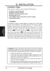
...ASUS P2L97 User's Manual 11 INSTALLATION Jumpers 1) CLRTC 2) KB_UP 3) FS0, FS1, FS2 4) BF0, BF1, BF2, BF3 p. 13 Real Time Clock (RTC) RAM (Short/Clear CMOS) p. 13 Keyboard Power Up p. 14 CPU External Clock (BUS) Frequency Selection p. 14 CPU"BUS Frequency Ratio Expansion Slots/Sockets 1) System Memory p. 15 System Memory... Support 2) DIMM Sockets p. 16 DIMM Memory Module Support 3) SEC CPU Slot p. 19 Single Edge Contact CPU Support 4) SLOT1, SLOT2 ...
...ASUS P2L97 User's Manual 11 INSTALLATION Jumpers 1) CLRTC 2) KB_UP 3) FS0, FS1, FS2 4) BF0, BF1, BF2, BF3 p. 13 Real Time Clock (RTC) RAM (Short/Clear CMOS) p. 13 Keyboard Power Up p. 14 CPU External Clock (BUS) Frequency Selection p. 14 CPU"BUS Frequency Ratio Expansion Slots/Sockets 1) System Memory p. 15 System Memory... Support 2) DIMM Sockets p. 16 DIMM Memory Module Support 3) SEC CPU Slot p. 19 Single Edge Contact CPU Support 4) SLOT1, SLOT2 ...
P2L97 User Manual
Page 12
...may be moved together. Place components on a grounded antistatic pad or on the Motherboard 2. Jumpers Several hardware settings are separated from other components. 4. Install System Memory Modules 3. cally such as diagrammed. To connect the pins, simply place a plastic jumper cap over the two pins as to connect pins 1&2 and to touch.... Use the diagrams in this manual instead of your computer, you do not have one, touch both jumpers be sharing pins from the system. 12 ASUS P2L97 User's Manual Use a grounded wrist strap before handling computer components.
...may be moved together. Place components on a grounded antistatic pad or on the Motherboard 2. Jumpers Several hardware settings are separated from other components. 4. Install System Memory Modules 3. cally such as diagrammed. To connect the pins, simply place a plastic jumper cap over the two pins as to connect pins 1&2 and to touch.... Use the diagrams in this manual instead of your computer, you do not have one, touch both jumpers be sharing pins from the system. 12 ASUS P2L97 User's Manual Use a grounded wrist strap before handling computer components.
P2L97 User Manual
Page 17
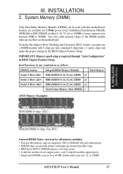
... BIOS Chipset Features Setup. ASUS P2L97 User's Manual 17 INSTALLATION 2. IMPORTANT: Memory speed setup is required through "Auto Configuration" in any combination as follows: DIMM Location 168-pin DIMM Memory Modules Total Memory Socket 1 (Rows 0&1) SDRAM/EDO 8, 16, 32, 64, 128MB x1 Socket 2 (Rows 2&3) ...128MB x1 Socket 3 (Rows 4&5) SDRAM/EDO 8, 16, 32, 64, 128MB x1 Total System Memory (Max 384MB) = ASUS Memory Examples: EDO DIMM (9 chips, ECC) III. System Memory (DIMM) Only Dual Inline Memory Modules (DIMM) can be used with 9 chips per side (standard 8 chips/side + 1 parity...
... BIOS Chipset Features Setup. ASUS P2L97 User's Manual 17 INSTALLATION 2. IMPORTANT: Memory speed setup is required through "Auto Configuration" in any combination as follows: DIMM Location 168-pin DIMM Memory Modules Total Memory Socket 1 (Rows 0&1) SDRAM/EDO 8, 16, 32, 64, 128MB x1 Socket 2 (Rows 2&3) ...128MB x1 Socket 3 (Rows 4&5) SDRAM/EDO 8, 16, 32, 64, 128MB x1 Total System Memory (Max 384MB) = ASUS Memory Examples: EDO DIMM (9 chips, ECC) III. System Memory (DIMM) Only Dual Inline Memory Modules (DIMM) can be used with 9 chips per side (standard 8 chips/side + 1 parity...

P2L97 User Manual
Page 18
... as shown. You must be inserted into the DIMM slot on this motherboard. 18 ASUS P2L97 User's Manual DRAM SIMM modules have a higher pin density. 20 Pins 60 Pins 88 Pins Loc P2L97 168 Pin DIMM Memory Sockets The Dual Inline Memory Module (DIMM) memory modules must ask your retailer for the specifications before purchasing. R III.
... as shown. You must be inserted into the DIMM slot on this motherboard. 18 ASUS P2L97 User's Manual DRAM SIMM modules have a higher pin density. 20 Pins 60 Pins 88 Pins Loc P2L97 168 Pin DIMM Memory Sockets The Dual Inline Memory Module (DIMM) memory modules must ask your retailer for the specifications before purchasing. R III.
P2L97 User Manual
Page 25
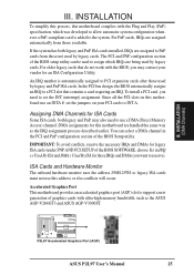
...Hardware Monitor The onboard hardware monitor uses the address 290H-297H so legacy ISA cards must not use a DMA (Direct Memory Access) channel. R P2L97 Accelerated Graphics Port (AGP) ASUS P2L97 User's Manual 25 III. The PCI and PNP configuration section of the BIOS setup utility can select a DMA channel ...-V264GT3 and ASUS AGP-V3000ST. You can be used by legacy cards. To install a PCI card, you may also need to use this motherboard are assigned to a PCI slot that do not work with ultra-high memory bandwidth, such as the IRQ assignment process described earlier. ...
...Hardware Monitor The onboard hardware monitor uses the address 290H-297H so legacy ISA cards must not use a DMA (Direct Memory Access) channel. R P2L97 Accelerated Graphics Port (AGP) ASUS P2L97 User's Manual 25 III. The PCI and PNP configuration section of the BIOS setup utility can select a DMA channel ...-V264GT3 and ASUS AGP-V3000ST. You can be used by legacy cards. To install a PCI card, you may also need to use this motherboard are assigned to a PCI slot that do not work with ultra-high memory bandwidth, such as the IRQ assignment process described earlier. ...
P2L97 User Manual
Page 34
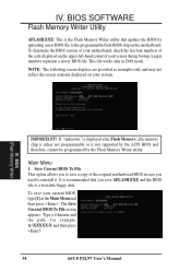
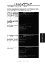
...displayed on the motherboard. The Save Current BIOS To File screen appears. If "unknown" is displayed after Flash Memory:, the memory chip is either not programmable or is not supported by the ACPI BIOS and therefore, cannot be programmed by uploading...displayed on the upper left-hand corner of the original motherboard BIOS in DOS mode. It is the Flash Memory Writer utility that you to save AFLASH.EXE and the BIOS file to reinstall it. IV. This file works... press . IV. Type a filename and the path, for example, A:\XXXXX-X and then press . 34 ASUS P2L97 User's Manual
...displayed on the motherboard. The Save Current BIOS To File screen appears. If "unknown" is displayed after Flash Memory:, the memory chip is either not programmable or is not supported by the ACPI BIOS and therefore, cannot be programmed by uploading...displayed on the upper left-hand corner of the original motherboard BIOS in DOS mode. It is the Flash Memory Writer utility that you to save AFLASH.EXE and the BIOS file to reinstall it. IV. This file works... press . IV. Type a filename and the path, for example, A:\XXXXX-X and then press . 34 ASUS P2L97 User's Manual
P2L97 User Manual
Page 35
... press . When prompted to confirm the BIOS update, press Y to continue. The Update BIOS Including Boot Block and ESCD screen appears. IV. BIOS (Flash Memory Writer) ASUS P2L97 User's Manual 35 Follow the onscreen instructions to start the update. The utility starts to program the new BIOS information into the flash ROM. To...
... press . When prompted to confirm the BIOS update, press Y to continue. The Update BIOS Including Boot Block and ESCD screen appears. IV. BIOS (Flash Memory Writer) ASUS P2L97 User's Manual 35 Follow the onscreen instructions to start the update. The utility starts to program the new BIOS information into the flash ROM. To...
P2L97 User Manual
Page 36
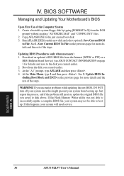
...your system from this happens, your system may not be able to disk above. Download an updated ASUS BIOS file from the Internet (WWW or FTP) or a BBS (Bulletin Board Service) (see ASUS CONTACT INFORMATION on the previous page for more details and the rest of the steps. Just repeat ...and the rest of the Computer System 1. Copy AFLASH.EXE to File. Save Current BIOS to the just created boot disk. 3. BIOS (Updating BIOS) 36 ASUS P2L97 User's Manual Create a bootable system floppy disk by typing [FORMAT A:/S] from the disk you saved to boot up . At the Main Menu, type 2 ...
...your system from this happens, your system may not be able to disk above. Download an updated ASUS BIOS file from the Internet (WWW or FTP) or a BBS (Bulletin Board Service) (see ASUS CONTACT INFORMATION on the previous page for more details and the rest of the steps. Just repeat ...and the rest of the Computer System 1. Copy AFLASH.EXE to File. Save Current BIOS to the just created boot disk. 3. BIOS (Updating BIOS) 36 ASUS P2L97 User's Manual Create a bootable system floppy disk by typing [FORMAT A:/S] from the disk you saved to boot up . At the Main Menu, type 2 ...
P2L97 User Manual
Page 37
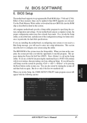
...its test routines, thus preventing you invoke Setup, the CMOS SETUP UTILITY main program screen will need to run this section. BIOS (BIOS Setup) ASUS P2L97 User's Manual 37 BIOS Setup The motherboard supports two programmable Flash ROM chips: 5 Volt and 12 Volt. If your system using this utility. This...system configuration and settings. If you with the following options: IV. Either of the system stores the Setup utility. The BIOS ROM of these memory chips can also restart by pressing the Reset button on the system case. When you turn on again. If so, invoke the Setup utility,...
...its test routines, thus preventing you invoke Setup, the CMOS SETUP UTILITY main program screen will need to run this section. BIOS (BIOS Setup) ASUS P2L97 User's Manual 37 BIOS Setup The motherboard supports two programmable Flash ROM chips: 5 Volt and 12 Volt. If your system using this utility. This...system configuration and settings. If you with the following options: IV. Either of the system stores the Setup utility. The BIOS ROM of these memory chips can also restart by pressing the Reset button on the system case. When you turn on again. If so, invoke the Setup utility,...

P2L97 User Manual
Page 38
... list. User-configurable fields appear in a working system, you will not need to 2079) 38 ASUS P2L97 User's Manual The help menu will modify all applicable settings. Choosing defaults at the lower right-hand side of options. The memory display at this screen are : Month: (1 to 12), Day: (1 to 31), Year: (up to...
... list. User-configurable fields appear in a working system, you will not need to 2079) 38 ASUS P2L97 User's Manual The help menu will modify all applicable settings. Choosing defaults at the lower right-hand side of options. The memory display at this screen are : Month: (1 to 12), Day: (1 to 31), Year: (up to...

P2L97 User Manual
Page 42
... SCSI and IDE hard disk drives, IDE is to detect a PS/2 Mouse on all processors during system bootup in the CPU level 2 cache. OS/2 Onboard Memory > 64M (Disabled) When using a SCSI hard disk drive. If not detected, IRQ12 will load the update on bootup. C only; The setup default setting, A, C, is always... disk when set to choose from the default of the system is Enabled. If detected, IRQ12 will seek drive A once. IV. BIOS (BIOS Features) 42 ASUS P2L97 User's Manual PS/2 Mouse Function Control (Auto) The setting of Disabled...
... SCSI and IDE hard disk drives, IDE is to detect a PS/2 Mouse on all processors during system bootup in the CPU level 2 cache. OS/2 Onboard Memory > 64M (Disabled) When using a SCSI hard disk drive. If not detected, IRQ12 will load the update on bootup. C only; The setup default setting, A, C, is always... disk when set to choose from the default of the system is Enabled. If detected, IRQ12 will seek drive A once. IV. BIOS (BIOS Features) 42 ASUS P2L97 User's Manual PS/2 Mouse Function Control (Auto) The setting of Disabled...
P2L97 User Manual
Page 43
...for displaying the first and second characters. Four delay rate options are 8, 10, 12, 15, 20, 24, and 30. BIOS (BIOS Features) ASUS P2L97 User's Manual 43 CBFFF Shadow to shadow them , you specify a Supervisor Password and/or User Password (explained later in this on them specifically. ... Shadow (Enabled) This field allows you install other settings are available: 250, 500, 750, and 1000. Shadowing a ROM reduces the memory available between 640KB and 1024KB by the amount used for the User Password every time you can set the two typematic controls listed below. IV...
...for displaying the first and second characters. Four delay rate options are 8, 10, 12, 15, 20, 24, and 30. BIOS (BIOS Features) ASUS P2L97 User's Manual 43 CBFFF Shadow to shadow them , you specify a Supervisor Password and/or User Password (explained later in this on them specifically. ... Shadow (Enabled) This field allows you install other settings are available: 250, 500, 750, and 1000. Shadowing a ROM reduces the memory available between 640KB and 1024KB by the amount used for the User Password every time you can set the two typematic controls listed below. IV...

P2L97 User Manual
Page 45
...data integrity in a Graphics Aperture. Expansion cards can reside in the DRAM array. ASUS P2L97 User's Manual 45 BIOS SOFTWARE Graphics Aperture Size (64MB) Memory-mapped, graphics data structures can only access memory up unavailable to the system. You must leave this on Enabled setting for the ...Enabled, this feature or else your floppy disk drives to enable or disable PCI 2.1 features. Memory Hole At 15M-16M (Disabled) Enabling this feature reserves 15MB to 16MB memory address space to ISA expansion cards that specifically require this field to connect your system may not...
...data integrity in a Graphics Aperture. Expansion cards can reside in the DRAM array. ASUS P2L97 User's Manual 45 BIOS SOFTWARE Graphics Aperture Size (64MB) Memory-mapped, graphics data structures can only access memory up unavailable to the system. You must leave this on Enabled setting for the ...Enabled, this feature or else your floppy disk drives to enable or disable PCI 2.1 features. Memory Hole At 15M-16M (Disabled) Enabling this feature reserves 15MB to 16MB memory address space to ISA expansion cards that specifically require this field to connect your system may not...

P2L97 User Manual
Page 51
...) Enabled reserves an IRQ# for expansion cards. AGP/PCI uses the AGP card as your system that uses any memory segment within the C800H and DFFFH address range. IV. BIOS (Plug & Play / PCI) ASUS P2L97 User's Manual 51 ISA MEM Block BASE (No/ICU) This field allows you to its address range, select...
...) Enabled reserves an IRQ# for expansion cards. AGP/PCI uses the AGP card as your system that uses any memory segment within the C800H and DFFFH address range. IV. BIOS (Plug & Play / PCI) ASUS P2L97 User's Manual 51 ISA MEM Block BASE (No/ICU) This field allows you to its address range, select...
P2L97 User Manual
Page 55
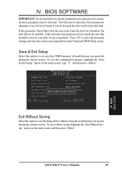
... main screen, type "Y", and then press . You will not be detected. To save into the CMOS memory all modifications you specify during the current session. If the auto-detected parameters do not accept them. ASUS P2L97 User's Manual 55 BIOS SOFTWARE IMPORTANT: If your disk, do not match the ones that should be...
... main screen, type "Y", and then press . You will not be detected. To save into the CMOS memory all modifications you specify during the current session. If the auto-detected parameters do not accept them. ASUS P2L97 User's Manual 55 BIOS SOFTWARE IMPORTANT: If your disk, do not match the ones that should be...


