P2L97 User Manual
Page 2
...number are registered trademarks of International Business Machines. • Symbios is defaced or missing. Product Name: ASUS P2L97 Manual Revision: 2.05 E266 Release Date: October 1998 2 ASUS P2L97 User's Manual Products and corporate names appearing in this manual, including the products and software described in... IBM and OS/2 are both printed on the following page. For previous or updated manuals, BIOS, drivers, or product release information, contact ASUS at http://www.asus.com.tw or through any means, except documentation kept by the purchaser for each product design ...
...number are registered trademarks of International Business Machines. • Symbios is defaced or missing. Product Name: ASUS P2L97 Manual Revision: 2.05 E266 Release Date: October 1998 2 ASUS P2L97 User's Manual Products and corporate names appearing in this manual, including the products and software described in... IBM and OS/2 are both printed on the following page. For previous or updated manuals, BIOS, drivers, or product release information, contact ASUS at http://www.asus.com.tw or through any means, except documentation kept by the purchaser for each product design ...
P2L97 User Manual
Page 4
CONTENTS I. Central Processing Unit (CPU 19 Universal Retention Mechanism 19 Heatsinks 19 Installing the Processor 20 ASUS Smart Thermal Solutions 22 Recommended Heatsinks for ISA Cards 25 ISA Cards and Hardware Monitor 25 5. INTRODUCTION... Writer Utility 34 Managing and Updating Your Motherboard's BIOS 36 6. BIOS Setup 37 Load Defaults 38 4 ASUS P2L97 User's Manual FEATURES 8 Features of the ASUS P2L97 Motherboard 10 Installation Steps 12 1. INSTALLATION 10 Layout of the ASUS P2L97 Motherboard 8 The ASUS P2L97 Motherboard 9 III. Jumpers 12 Jumper Settings 13...
CONTENTS I. Central Processing Unit (CPU 19 Universal Retention Mechanism 19 Heatsinks 19 Installing the Processor 20 ASUS Smart Thermal Solutions 22 Recommended Heatsinks for ISA Cards 25 ISA Cards and Hardware Monitor 25 5. INTRODUCTION... Writer Utility 34 Managing and Updating Your Motherboard's BIOS 36 6. BIOS Setup 37 Load Defaults 38 4 ASUS P2L97 User's Manual FEATURES 8 Features of the ASUS P2L97 Motherboard 10 Installation Steps 12 1. INSTALLATION 10 Layout of the ASUS P2L97 Motherboard 8 The ASUS P2L97 Motherboard 9 III. Jumpers 12 Jumper Settings 13...

P2L97 User Manual
Page 5
CONTENTS Standard CMOS Setup 38 Details of Standard CMOS Setup 38 BIOS Features Setup 41 Details of BIOS Features Setup 41 Chipset Features Setup 44 Details of Chipset Features Setup 44 Power Management Setup 47 Details of Power Management Setup 47 PNP and PCI Setup 50 Details of PNP and PCI Setup 50 Load BIOS Defaults 52 Load Setup Defaults 52 Supervisor Password and User Password 53 IDE HDD Auto Detection 54 Save & Exit Setup 55 Exit Without Saving 55 ASUS P2L97 User's Manual 5
CONTENTS Standard CMOS Setup 38 Details of Standard CMOS Setup 38 BIOS Features Setup 41 Details of BIOS Features Setup 41 Chipset Features Setup 44 Details of Chipset Features Setup 44 Power Management Setup 47 Details of Power Management Setup 47 PNP and PCI Setup 50 Details of PNP and PCI Setup 50 Load BIOS Defaults 52 Load Setup Defaults 52 Supervisor Password and User Password 53 IDE HDD Auto Detection 54 Save & Exit Setup 55 Exit Without Saving 55 ASUS P2L97 User's Manual 5

P2L97 User Manual
Page 7
...is complete. INTRODUCTION How this product Instructions on setting up the motherboard and jumper Instructions on setting up the BIOS software Item Checklist Check that your retailer. (1) ASUS Motherboard (1) Univeral retention mechanism for SECC/SECC2/SEPP (1) IDE ribbon cable for master and slave drives (1) Floppy... (1) Bag of spare jumper caps (1) Support CD with drivers and utilities (1) Motherboard user's manual Infrared module (optional) ASUS PCI-SC200 Fast-SCSI or PCI-SC860 Ultra-Fast SCSI card (optional) ASUS P2L97 User's Manual 7 INTRODUCTION (Manual / Checklist) I . I .
...is complete. INTRODUCTION How this product Instructions on setting up the motherboard and jumper Instructions on setting up the BIOS software Item Checklist Check that your retailer. (1) ASUS Motherboard (1) Univeral retention mechanism for SECC/SECC2/SEPP (1) IDE ribbon cable for master and slave drives (1) Floppy... (1) Bag of spare jumper caps (1) Support CD with drivers and utilities (1) Motherboard user's manual Infrared module (optional) ASUS PCI-SC200 Fast-SCSI or PCI-SC860 Ultra-Fast SCSI card (optional) ASUS P2L97 User's Manual 7 INTRODUCTION (Manual / Checklist) I . I .
P2L97 User Manual
Page 8
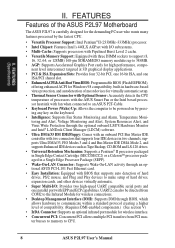
...Package (SEPP). • Wake-On-LAN Connector: Supports Wake-On-LAN activity through BIOS, which allows hardware to communicate within a standard protocol creating a higher level of the ASUS P2L97 Motherboard The ASUS P2L97 is carefully designed for wireless interface. • Concurrent PCI: Concurrent PCI allows multiple... PCI transfers from PCI master busses to memory to CPU. 8 ASUS P2L97 User's Manual UART2 can also be powered on by the fastest CPU. • Versatile Processor Support: Intel Pentium® II...
...Package (SEPP). • Wake-On-LAN Connector: Supports Wake-On-LAN activity through BIOS, which allows hardware to communicate within a standard protocol creating a higher level of the ASUS P2L97 Motherboard The ASUS P2L97 is carefully designed for wireless interface. • Concurrent PCI: Concurrent PCI allows multiple... PCI transfers from PCI master busses to memory to CPU. 8 ASUS P2L97 User's Manual UART2 can also be powered on by the fastest CPU. • Versatile Processor Support: Intel Pentium® II...
P2L97 User Manual
Page 10
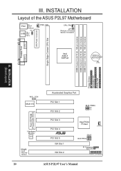
...Flash EEPROM (Programable BIOS) Accelerated Graphics Port PCI Slot 1 PCI Slot 2 PCI Slot 3 PCI Slot 4 R PCI Slot 5 ISA Slot 1 ISA Slot 2 BUS FREQ FS0 FS1 FS2 Intel PIIX4 PCIset CHA_FAN BF0 BF2 BF1 BF3 BUS FREQ IR Connector IDE LED Panel Connectors 10 ASUS P2L97 User's Manual DIMM ... pin module) DIMM Socket 3 (64/72 bit, 168 pin module) ATX Power Conenctor Single Edge Contact CPU Slot III. INSTALLATION Layout of the ASUS P2L97 Motherboard PS/2 Top: Mouse Bottom: Keyboard KB_UP Top: USB USB 1 Bottom: USB 2 PWR_FAN CPU_FAN JP1 Pentium II Thermal Sensor Connector COM 1 ...
...Flash EEPROM (Programable BIOS) Accelerated Graphics Port PCI Slot 1 PCI Slot 2 PCI Slot 3 PCI Slot 4 R PCI Slot 5 ISA Slot 1 ISA Slot 2 BUS FREQ FS0 FS1 FS2 Intel PIIX4 PCIset CHA_FAN BF0 BF2 BF1 BF3 BUS FREQ IR Connector IDE LED Panel Connectors 10 ASUS P2L97 User's Manual DIMM ... pin module) DIMM Socket 3 (64/72 bit, 168 pin module) ATX Power Conenctor Single Edge Contact CPU Slot III. INSTALLATION Layout of the ASUS P2L97 Motherboard PS/2 Top: Mouse Bottom: Keyboard KB_UP Top: USB USB 1 Bottom: USB 2 PWR_FAN CPU_FAN JP1 Pentium II Thermal Sensor Connector COM 1 ...
P2L97 User Manual
Page 12
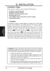
... steps: 1. To protect them against damage from other components. 4. Install the Central Processing Unit (CPU) 4. Setup the BIOS Software 1. Install System Memory Modules 3. III. If you do not have one, touch both jumpers be sharing pins from static...no connection, connect pins 1&2, and connect pins 2&3, respectively. III. Jumpers Several hardware settings are separated from the system. 12 ASUS P2L97 User's Manual Connect Ribbon Cables, Cabinet Wires, and Power Supply 6. Computer motherboards and expansion cards contain very delicate Integrated Circuit ...
... steps: 1. To protect them against damage from other components. 4. Install the Central Processing Unit (CPU) 4. Setup the BIOS Software 1. Install System Memory Modules 3. III. If you do not have one, touch both jumpers be sharing pins from static...no connection, connect pins 1&2, and connect pins 2&3, respectively. III. Jumpers Several hardware settings are separated from the system. 12 ASUS P2L97 User's Manual Connect Ribbon Cables, Cabinet Wires, and Power Supply 6. Computer motherboards and expansion cards contain very delicate Integrated Circuit ...
P2L97 User Manual
Page 13
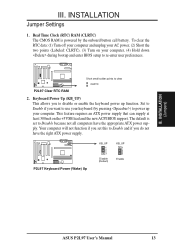
...to use your AC power, (2) Short the two points (Labeled: CLRTC), (3) Turn on the +5VSB lead and the new ACPI BIOS support. Set to Enable if you to power up function. R P2L97 Keyboard Power (Wake) Up KB_UP 1 2 3 Disable (Default) KB_UP 1 2 3 Enable III. To clear the RTC data: ...your computer, (4) Hold down during bootup and enter BIOS setup to clear CLRTC P2L97 Clear RTC RAM 2. Your computer will not function if you set to Enable and if you do not have the appropriate ATX power supply. INSTALLATION (Jumpers) ASUS P2L97 User's Manual 13 III. Real Time Clock (RTC...
...to use your AC power, (2) Short the two points (Labeled: CLRTC), (3) Turn on the +5VSB lead and the new ACPI BIOS support. Set to Enable if you to power up function. R P2L97 Keyboard Power (Wake) Up KB_UP 1 2 3 Disable (Default) KB_UP 1 2 3 Enable III. To clear the RTC data: ...your computer, (4) Hold down during bootup and enter BIOS setup to clear CLRTC P2L97 Clear RTC RAM 2. Your computer will not function if you set to Enable and if you do not have the appropriate ATX power supply. INSTALLATION (Jumpers) ASUS P2L97 User's Manual 13 III. Real Time Clock (RTC...
P2L97 User Manual
Page 17
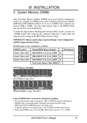
One side (with higher pin density than EDO chips. • BIOS shows EDO or SDRAM memory on the motherboard. ASUS P2L97 User's Manual 17 INSTALLATION 2. IMPORTANT: Memory speed setup is required through "Auto Configuration" in any combination as follows: DIMM Location 168-pin ... not support parity, only 9 chip/side modules support parity. • Single-sided DIMMs come in 16 or 64 MB, double-sided come in the BIOS Chipset Features Setup. To utilize the chipset's Error Checking and Correction (ECC) feature, you must use a DIMM module with this motherboard. III. System ...
One side (with higher pin density than EDO chips. • BIOS shows EDO or SDRAM memory on the motherboard. ASUS P2L97 User's Manual 17 INSTALLATION 2. IMPORTANT: Memory speed setup is required through "Auto Configuration" in any combination as follows: DIMM Location 168-pin ... not support parity, only 9 chip/side modules support parity. • Single-sided DIMMs come in 16 or 64 MB, double-sided come in the BIOS Chipset Features Setup. To utilize the chipset's Error Checking and Correction (ECC) feature, you must use a DIMM module with this motherboard. III. System ...

P2L97 User Manual
Page 24
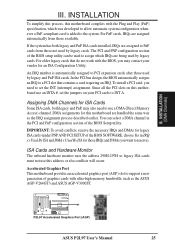
...resource settings being used by a particular device (to PCI cards. Carefully align the card's connectors and press firmly. 4. Set up the BIOS if necessary (such as jumpers. 2. If your power supply when adding or removing expansion cards or other system components. System IRQs are ...install it in the ISA expansion bus first, then any necessary hardware or software settings for possible future use at the same time. 24 ASUS P2L97 User's Manual INSTALLATION 4. Unplug your motherboard has audio onboard, an extra 3 IRQs will experience problems when those two devices are already ...
...resource settings being used by a particular device (to PCI cards. Carefully align the card's connectors and press firmly. 4. Set up the BIOS if necessary (such as jumpers. 2. If your power supply when adding or removing expansion cards or other system components. System IRQs are ...install it in the ISA expansion bus first, then any necessary hardware or software settings for possible future use at the same time. 24 ASUS P2L97 User's Manual INSTALLATION 4. Unplug your motherboard has audio onboard, an extra 3 IRQs will experience problems when those two devices are already ...
P2L97 User Manual
Page 25
...) III. An IRQ number is added to use an INTA #, set the INT (interrupt) assignment. In the PCI bus design, the BIOS automatically assigns an IRQ to PCI expansion cards after those not used to assign which was developed to allow automatic system configuration whenever a PnP-... assigned to a PCI slot that do not work with ultra-high memory bandwidth, such as the IRQ assignment process described earlier. R P2L97 Accelerated Graphics Port (AGP) ASUS P2L97 User's Manual 25 For PnP cards, IRQs are assigned to reserve). To install a PCI card, you may also need to INT...
...) III. An IRQ number is added to use an INTA #, set the INT (interrupt) assignment. In the PCI bus design, the BIOS automatically assigns an IRQ to PCI expansion cards after those not used to assign which was developed to allow automatic system configuration whenever a PnP-... assigned to a PCI slot that do not work with ultra-high memory bandwidth, such as the IRQ assignment process described earlier. R P2L97 Accelerated Graphics Port (AGP) ASUS P2L97 User's Manual 25 For PnP cards, IRQs are assigned to reserve). To install a PCI card, you may also need to INT...

P2L97 User Manual
Page 26
...will direct IRQ12 to the power connector on standard AT keyboards. PS/2 Keyboard (6-pin Female) 2. INSTALLATION 5. PS/2 Mouse (6-pin Female) 26 ASUS P2L97 User's Manual III. The four corners of the connectors are labeled on the Pin 1 side of the connector. IMPORTANT: Ribbon cables should always be... less than 6in. (15cm) from jumpers in BIOS Features Setup of the Motherboard." Placing jumper caps over these will cause damage to mini DIN adapter on hard drives and floppy drives....
...will direct IRQ12 to the power connector on standard AT keyboards. PS/2 Keyboard (6-pin Female) 2. INSTALLATION 5. PS/2 Mouse (6-pin Female) 26 ASUS P2L97 User's Manual III. The four corners of the connectors are labeled on the Pin 1 side of the connector. IMPORTANT: Ribbon cables should always be... less than 6in. (15cm) from jumpers in BIOS Features Setup of the Motherboard." Placing jumper caps over these will cause damage to mini DIN adapter on hard drives and floppy drives....

P2L97 User Manual
Page 27
...the other serial devices. Parallel (Printer) Port (25-pin Female) 4. See "Onboard Serial Port" in Chipset Features Setup of the BIOS SOFTWARE. NOTE: Orient the red stripe to the serial port. Floppy Disk Drive Connector (34-1pin FLOPPY) This connector supports the provided ...connecting the single end to prevent inserting in Chipset Features Setup of the BIOS SOFTWARE. Parallel Printer Connector (25-pin Female) You can be connected to Pin 1 Floppy Drive Connector Pin 1 R P2L97 Floppy Disk Drive Connector ASUS P2L97 User's Manual 27 III. COM 1 COM 2 Serial Ports (9-pin Male...
...the other serial devices. Parallel (Printer) Port (25-pin Female) 4. See "Onboard Serial Port" in Chipset Features Setup of the BIOS SOFTWARE. NOTE: Orient the red stripe to the serial port. Floppy Disk Drive Connector (34-1pin FLOPPY) This connector supports the provided ...connecting the single end to prevent inserting in Chipset Features Setup of the BIOS SOFTWARE. Parallel Printer Connector (25-pin Female) You can be connected to Pin 1 Floppy Drive Connector Pin 1 R P2L97 Floppy Disk Drive Connector ASUS P2L97 User's Manual 27 III. COM 1 COM 2 Serial Ports (9-pin Male...

P2L97 User Manual
Page 28
...wrong orientation when using one operating system on an IDE drive and another ribbon cable on a SCSI drive and select the boot disk through BIOS Features Setup. Primary / Secondary IDE connectors (Two 40-1pin IDE) These connectors support the provided IDE hard disk ribbon cable. INSTALLATION ... 1 Universal Serial Bus (USB) 2 7. You may configure two hard disks to Pin 1 Pin 1 Secondary IDE Connector P2L97 IDE Connectors Primary IDE Connector 28 ASUS P2L97 User's Manual If you install two hard disks, you must configure the second drive to your hard disk for connecting USB devices...
...wrong orientation when using one operating system on an IDE drive and another ribbon cable on a SCSI drive and select the boot disk through BIOS Features Setup. Primary / Secondary IDE connectors (Two 40-1pin IDE) These connectors support the provided IDE hard disk ribbon cable. INSTALLATION ... 1 Universal Serial Bus (USB) 2 7. You may configure two hard disks to Pin 1 Pin 1 Secondary IDE Connector P2L97 IDE Connectors Primary IDE Connector 28 ASUS P2L97 User's Manual If you install two hard disks, you must configure the second drive to your hard disk for connecting USB devices...

P2L97 User Manual
Page 32
... while in the ON mode for the connector, you want to use this connector, "Suspend Switch" in the BIOS but the keyboard will always allow keyboard locking. 19. The system power LED shows the status of the system's... power supply. 17. R III. The LED will be on the position of the BIOS SOFTWARE section should be instantly decreased to this lead. System Management Interrupt Lead (SMI) This allows the user ...) This 4-pin connector connects to prolong the life of the system's power. 16. P2L97 System Panel Connections 32 ASUS P2L97 User's Manual
... while in the ON mode for the connector, you want to use this connector, "Suspend Switch" in the BIOS but the keyboard will always allow keyboard locking. 19. The system power LED shows the status of the system's... power supply. 17. R III. The LED will be on the position of the BIOS SOFTWARE section should be instantly decreased to this lead. System Management Interrupt Lead (SMI) This allows the user ...) This 4-pin connector connects to prolong the life of the system's power. 16. P2L97 System Panel Connections 32 ASUS P2L97 User's Manual

P2L97 User Manual
Page 33
...starting with "green" standards or if it has a power standby feature. For ATX power supplies, the system LED will appear on test. ASUS P2L97 User's Manual 33 After all switches are off the power switch. The system will light. If you need to your operating system. Recheck ...your jumper settings and connections or call your operating system before switching off (in the next section, BIOS SOFTWARE. * Powering Off your computer: You must first exit or shut down your system user's manual. 4. Be sure that is pressed...
...starting with "green" standards or if it has a power standby feature. For ATX power supplies, the system LED will appear on test. ASUS P2L97 User's Manual 33 After all switches are off the power switch. The system will light. If you need to your operating system. Recheck ...your jumper settings and connections or call your operating system before switching off (in the next section, BIOS SOFTWARE. * Powering Off your computer: You must first exit or shut down your system user's manual. 4. Be sure that is pressed...
P2L97 User Manual
Page 34
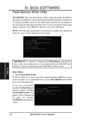
... in case you save your current BIOS, type [1] at the Main Menu and then press . Type a filename and the path, for example, A:\XXXXX-X and then press . 34 ASUS P2L97 User's Manual BIOS (Flash Memory Writer) IMPORTANT! To save AFLASH.EXE and the BIOS file to save a copy of ...your system. The Save Current BIOS To File screen appears. NOTE: The following screen displays are provided as ...
... in case you save your current BIOS, type [1] at the Main Menu and then press . Type a filename and the path, for example, A:\XXXXX-X and then press . 34 ASUS P2L97 User's Manual BIOS (Flash Memory Writer) IMPORTANT! To save AFLASH.EXE and the BIOS file to save a copy of ...your system. The Save Current BIOS To File screen appears. NOTE: The following screen displays are provided as ...
P2L97 User Manual
Page 35
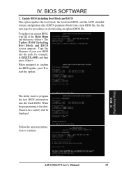
...Successfully will be displayed. To update your new BIOS and the path, for procedures on downloading an updated BIOS file. BIOS (Flash Memory Writer) ASUS P2L97 User's Manual 35 The utility starts to start the update. Type the filename of your current BIOS, type [2] at the Main Menu and then... press . Update BIOS Including Boot Block and ESCD This option...
...Successfully will be displayed. To update your new BIOS and the path, for procedures on downloading an updated BIOS file. BIOS (Flash Memory Writer) ASUS P2L97 User's Manual 35 The utility starts to start the update. Type the filename of your current BIOS, type [2] at the Main Menu and then... press . Update BIOS Including Boot Block and ESCD This option...
P2L97 User Manual
Page 36
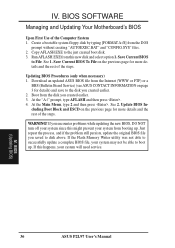
...might prevent your system from the DOS prompt without creating "AUTOEXEC.BAT" and "CONFIG.SYS" files. 2. BIOS (Updating BIOS) 36 ASUS P2L97 User's Manual Save Current BIOS to disk above. Update BIOS Including Boot Block and ESCD on the previous page for more details and the rest of the Computer System 1.... Main Menu, type 2 and then press . If you saved to File. See 1. Download an updated ASUS BIOS file from the Internet (WWW or FTP) or a BBS (Bulletin Board Service) (see ASUS CONTACT INFORMATION on page 3 for more details and the rest of the steps. Boot from this happens, ...
...might prevent your system from the DOS prompt without creating "AUTOEXEC.BAT" and "CONFIG.SYS" files. 2. BIOS (Updating BIOS) 36 ASUS P2L97 User's Manual Save Current BIOS to disk above. Update BIOS Including Boot Block and ESCD on the previous page for more details and the rest of the Computer System 1.... Main Menu, type 2 and then press . If you saved to File. See 1. Download an updated ASUS BIOS file from the Internet (WWW or FTP) or a BBS (Bulletin Board Service) (see ASUS CONTACT INFORMATION on page 3 for more details and the rest of the steps. Boot from this happens, ...
P2L97 User Manual
Page 37
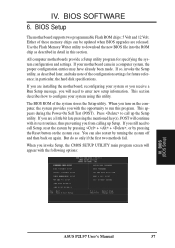
...routines, thus preventing you turn on again. in this utility. IV. Use the Flash Memory Writer utility to run this program. BIOS (BIOS Setup) ASUS P2L97 User's Manual 37 All computer motherboards provide a Setup utility program for future reference; This section describes how to enter new setup ...methods fail. When you invoke Setup, the CMOS SETUP UTILITY main program screen will continue with the following options: IV. BIOS SOFTWARE 6. The BIOS ROM of these memory chips can also restart by pressing the Reset button on the system case. If you still need...
...routines, thus preventing you turn on again. in this utility. IV. Use the Flash Memory Writer utility to run this program. BIOS (BIOS Setup) ASUS P2L97 User's Manual 37 All computer motherboards provide a Setup utility program for future reference; This section describes how to enter new setup ...methods fail. When you invoke Setup, the CMOS SETUP UTILITY main program screen will continue with the following options: IV. BIOS SOFTWARE 6. The BIOS ROM of these memory chips can also restart by pressing the Reset button on the system case. If you still need...


