P2B-L User Manual
Page 1
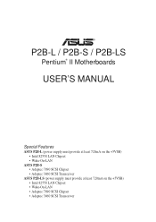
R P2B-L / P2B-S / P2B-LS Pentium® II Motherboards USER'S MANUAL Special Features ASUS P2B-L (power supply must provide at least 720mA on the +5VSB) • Intel 82558 LAN Chipset • Wake-On-LAN ASUS P2B-S • Adaptec 7890 SCSI Chipset • Adaptec 3860 SCSI Transceiver ASUS P2B-LS (power supply must provide at least 720mA on the +5VSB) • Intel 82558 LAN Chipset • Wake-On-LAN • Adaptec 7890 SCSI Chipset • Adaptec 3860 SCSI Transceiver
R P2B-L / P2B-S / P2B-LS Pentium® II Motherboards USER'S MANUAL Special Features ASUS P2B-L (power supply must provide at least 720mA on the +5VSB) • Intel 82558 LAN Chipset • Wake-On-LAN ASUS P2B-S • Adaptec 7890 SCSI Chipset • Adaptec 3860 SCSI Transceiver ASUS P2B-LS (power supply must provide at least 720mA on the +5VSB) • Intel 82558 LAN Chipset • Wake-On-LAN • Adaptec 7890 SCSI Chipset • Adaptec 3860 SCSI Transceiver
P2B-L User Manual
Page 4
... 43 Chipset Features Setup 46 Details of Chipset Features Setup 46 Power Management Setup 49 Details of Power Management Setup 49 4 ASUS P2B-L/P2B-S/P2B-LS User's Manual External Connectors 26 Power Connection Procedures 35 IV. INSTALLATION ASUS P2B-L/P2B-S/P2B-LS Motherboard Layout 10 Installation Steps 12 1. BIOS SOFTWARE Main Menu 36 Flash Memory Writer Utility 36 Managing and Updating Your...
... 43 Chipset Features Setup 46 Details of Chipset Features Setup 46 Power Management Setup 49 Details of Power Management Setup 49 4 ASUS P2B-L/P2B-S/P2B-LS User's Manual External Connectors 26 Power Connection Procedures 35 IV. INSTALLATION ASUS P2B-L/P2B-S/P2B-LS Motherboard Layout 10 Installation Steps 12 1. BIOS SOFTWARE Main Menu 36 Flash Memory Writer Utility 36 Managing and Updating Your...

P2B-L User Manual
Page 7
...specifications Instructions on setting up the BIOS software ASUS Smart Motherboard Support CD BIOS supported Desktop Management Interface Information on setting up the motherboard. INTRODUCTION How this Manual is Organized This manual is complete. Introduction II. BIOS Software ... jumpers (1) Support drivers and utilities (1) User's Manual 68-pin Ultra2 SCSI cable with terminator (optional) 68-pin Fast & Wide SCSI cable (optional) 50-pin Fast SCSI cable (optional) Network condition connector module (optional) ASUS P2B-L/P2B-S/P2B-LS User's Manual 7 I. Support Software VI.
...specifications Instructions on setting up the BIOS software ASUS Smart Motherboard Support CD BIOS supported Desktop Management Interface Information on setting up the motherboard. INTRODUCTION How this Manual is Organized This manual is complete. Introduction II. BIOS Software ... jumpers (1) Support drivers and utilities (1) User's Manual 68-pin Ultra2 SCSI cable with terminator (optional) 68-pin Fast & Wide SCSI cable (optional) 50-pin Fast SCSI cable (optional) Network condition connector module (optional) ASUS P2B-L/P2B-S/P2B-LS User's Manual 7 I. Support Software VI.
P2B-L User Manual
Page 8
... 3 mode" (3.5-inch disk drive: 1.2MB) and LS-120 floppy disk drives (3.5-inch disk drive: 120 MB, 1.44MB, 720KB). II. FEATURES Specifications II. FEATURES Features The ASUS P2B-L/P2B-S/P2B-LS motherboards are also supported without affecting system performance by the fastest... Resources Alert, and Virus Write Protection through the onboard Hardware Monitor, Intel LANDesk Client Manager (LDCM), and ASUS PC Probe software. • Super Multi-I /O subsystems and front-side bus (FSB) platform, which boosts...CD-ROM or SCSI device boot-up to CPU. 8 ASUS P2B-L/P2B-S/P2B-LS User's Manual
... 3 mode" (3.5-inch disk drive: 1.2MB) and LS-120 floppy disk drives (3.5-inch disk drive: 120 MB, 1.44MB, 720KB). II. FEATURES Specifications II. FEATURES Features The ASUS P2B-L/P2B-S/P2B-LS motherboards are also supported without affecting system performance by the fastest... Resources Alert, and Virus Write Protection through the onboard Hardware Monitor, Intel LANDesk Client Manager (LDCM), and ASUS PC Probe software. • Super Multi-I /O subsystems and front-side bus (FSB) platform, which boosts...CD-ROM or SCSI device boot-up to CPU. 8 ASUS P2B-L/P2B-S/P2B-LS User's Manual

P2B-L User Manual
Page 9
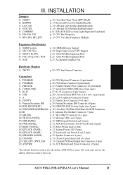
... (DMI): Supports DMI through BIOS, which allows hardware to communicate within a standard protocol creating a higher level of compatibility. (Requires DMI-enabled components.) II. II. FEATURES Motherboard Parts ASUS P2B-L/P2B-S/P2B-LS Motherboard SEC CPU Slot T: PS/2 Mouse B: PS/2 Keyboard T: USB Port 1 B: USB Port 2 COM 1 (Bottom) Parallel (Top) Serial (Bottom) COM 2 (Bottom) Intel ...-Fast/ Wide SCSI Chipset (optional) Accelerated Graphics Port 4PCI Slots Multi-I/O Hardware Monitor 2 ISA Slots Intel PIIX4E Programmable PCIset 2Mbit Flash ROM ASUS P2B-L/P2B-S/P2B-LS User's Manual 9
... (DMI): Supports DMI through BIOS, which allows hardware to communicate within a standard protocol creating a higher level of compatibility. (Requires DMI-enabled components.) II. II. FEATURES Motherboard Parts ASUS P2B-L/P2B-S/P2B-LS Motherboard SEC CPU Slot T: PS/2 Mouse B: PS/2 Keyboard T: USB Port 1 B: USB Port 2 COM 1 (Bottom) Parallel (Top) Serial (Bottom) COM 2 (Bottom) Intel ...-Fast/ Wide SCSI Chipset (optional) Accelerated Graphics Port 4PCI Slots Multi-I/O Hardware Monitor 2 ISA Slots Intel PIIX4E Programmable PCIset 2Mbit Flash ROM ASUS P2B-L/P2B-S/P2B-LS User's Manual 9
P2B-L User Manual
Page 10
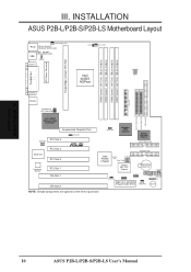
INSTALLATION Board Layout 10 ASUS P2B-L/P2B-S/P2B-LS User's Manual FS0 68 34 34 68 COM 2 RJ-45 1 FLOPPY LAN Activity LED Connector 35 1 35 1 50-Pin SCSI 1 68-Pin Wide SCSI 68-Pin Ultra2 ... CHASSIS WOL_CON EXTBATT 2Mbit Flash EEPROM (Programmable BIOS) CHA_FAN PANEL IDELED Combine IR Speaker NOTE: Greyed components are optional at the time of purchase. INSTALLATION ASUS P2B-L/P2B-S/P2B-LS Motherboard Layout DIMM Socket 0 (64/72 bit, 168 pin module) DIMM Socket 1 (64/72 bit, 168 pin module) DIMM Socket 2 (64/72 bit, 168 pin module...
INSTALLATION Board Layout 10 ASUS P2B-L/P2B-S/P2B-LS User's Manual FS0 68 34 34 68 COM 2 RJ-45 1 FLOPPY LAN Activity LED Connector 35 1 35 1 50-Pin SCSI 1 68-Pin Wide SCSI 68-Pin Ultra2 ... CHASSIS WOL_CON EXTBATT 2Mbit Flash EEPROM (Programmable BIOS) CHA_FAN PANEL IDELED Combine IR Speaker NOTE: Greyed components are optional at the time of purchase. INSTALLATION ASUS P2B-L/P2B-S/P2B-LS Motherboard Layout DIMM Socket 0 (64/72 bit, 168 pin module) DIMM Socket 1 (64/72 bit, 168 pin module) DIMM Socket 2 (64/72 bit, 168 pin module...
P2B-L User Manual
Page 11
... Lead (4-1 pins) 22) CHA_/CPU_/PWR_FAN p. 33 Chassis/CPU/Power Supply Fan Connectors (3 pins) 23) ATXPWR p. 34 ATX Motherboard Power Connector (20 pins) *The onboard hardware monitor uses the address 290H-297H so legacy ISA cards must not use this address, otherwise conflicts will occur. ASUS P2B-L/P2B-S/P2B-LS User's Manual 11 INSTALLATION Board Layout III.
... Lead (4-1 pins) 22) CHA_/CPU_/PWR_FAN p. 33 Chassis/CPU/Power Supply Fan Connectors (3 pins) 23) ATXPWR p. 34 ATX Motherboard Power Connector (20 pins) *The onboard hardware monitor uses the address 290H-297H so legacy ISA cards must not use this address, otherwise conflicts will occur. ASUS P2B-L/P2B-S/P2B-LS User's Manual 11 INSTALLATION Board Layout III.

P2B-L User Manual
Page 12
...shown graphi- Install System Memory Modules 3. The jumper settings will also be moved together. Setup the BIOS Software 1. Computer motherboards, baseboards and components, such as [----], [1-2], [2-3] for Open (Off). Use a grounded wrist strap before handling computer ...ASUS P2B-L/P2B-S/P2B-LS User's Manual INSTALLATION Installation Steps Before using your computer. 1. Set Jumpers on the inside. 2. Use the diagrams in this manual instead of jumpers. Hold components by the edges and try not to connect jumper pins (JP) on your computer, you work on the motherboard...
...shown graphi- Install System Memory Modules 3. The jumper settings will also be moved together. Setup the BIOS Software 1. Computer motherboards, baseboards and components, such as [----], [1-2], [2-3] for Open (Off). Use a grounded wrist strap before handling computer ...ASUS P2B-L/P2B-S/P2B-LS User's Manual INSTALLATION Installation Steps Before using your computer. 1. Set Jumpers on the inside. 2. Use the diagrams in this manual instead of jumpers. Hold components by the edges and try not to connect jumper pins (JP) on your computer, you work on the motherboard...
P2B-L User Manual
Page 14
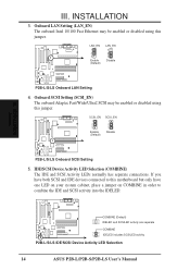
... and SCSILED activity are separate COMBINE IDELED includes SCSILED activity P2B-L/S/LS IDE/SCSI Device Activity LED Selection 14 ASUS P2B-L/P2B-S/P2B-LS User's Manual INSTALLATION 3. IDE/SCSI Device Activity LED Selection (COMBINE) The IDE and SCSI Activity LEDs normally has separate connections. LAN_EN 1 2 3 Enable (Default) LAN_EN 1 2 3 Disable P2B-L/S/LS Onboard LAN Setting 4. INSTALLATION Jumpers III. Onboard LAN Setting...
... and SCSILED activity are separate COMBINE IDELED includes SCSILED activity P2B-L/S/LS IDE/SCSI Device Activity LED Selection 14 ASUS P2B-L/P2B-S/P2B-LS User's Manual INSTALLATION 3. IDE/SCSI Device Activity LED Selection (COMBINE) The IDE and SCSI Activity LEDs normally has separate connections. LAN_EN 1 2 3 Enable (Default) LAN_EN 1 2 3 Disable P2B-L/S/LS Onboard LAN Setting 4. INSTALLATION Jumpers III. Onboard LAN Setting...
P2B-L User Manual
Page 17
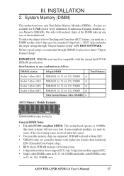
...in IV. INSTALLATION System Memory SDRAM DIMM (8 chips, Non-ECC) General DIMM Notes • Use only PC100-compliant DIMMs. This motherboard operates at 100MHz, thus most systems will not even boot if non-compliant modules are used must use a DIMM module with memory... ECC. • SDRAM chips are available for 3.3Volt (power level) unbuffered Synchronous Dynamic Random Access Memory (SDRAM). ASUS P2B-L/P2B-S/P2B-LS User's Manual 17 System Memory (DIMM) This motherboard uses only Dual Inline Memory Modules (DIMMs). BIOS SOFTWARE. Install memory in 32, 64, 128, 256MB sizes. Sockets...
...in IV. INSTALLATION System Memory SDRAM DIMM (8 chips, Non-ECC) General DIMM Notes • Use only PC100-compliant DIMMs. This motherboard operates at 100MHz, thus most systems will not even boot if non-compliant modules are used must use a DIMM module with memory... ECC. • SDRAM chips are available for 3.3Volt (power level) unbuffered Synchronous Dynamic Random Access Memory (SDRAM). ASUS P2B-L/P2B-S/P2B-LS User's Manual 17 System Memory (DIMM) This motherboard uses only Dual Inline Memory Modules (DIMMs). BIOS SOFTWARE. Install memory in 32, 64, 128, 256MB sizes. Sockets...
P2B-L User Manual
Page 18
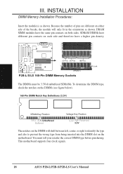
This motherboard supports four clock signals. 18 ASUS P2B-L/P2B-S/P2B-LS User's Manual You must be 3.3Volt unbuffered SDRAMs. To determine the DIMM type, check the notches on the DIMMs (see figure below). 168-Pin DIMM Notch Key .... 20 Pins 60 Pins 88 Pins Lock (FRONT) P2B-L/S/LS 168-Pin DIMM Memory Sockets The DIMMs must tell your retailer the correct DIMM type before purchasing. SDRAM DIMMs have different pin contacts on each side and therefore have the same pin contacts on the motherboard. INSTALLATION System Memory III. R III. Because the...
This motherboard supports four clock signals. 18 ASUS P2B-L/P2B-S/P2B-LS User's Manual You must be 3.3Volt unbuffered SDRAMs. To determine the DIMM type, check the notches on the DIMMs (see figure below). 168-Pin DIMM Notch Key .... 20 Pins 60 Pins 88 Pins Lock (FRONT) P2B-L/S/LS 168-Pin DIMM Memory Sockets The DIMMs must tell your retailer the correct DIMM type before purchasing. SDRAM DIMMs have different pin contacts on each side and therefore have the same pin contacts on the motherboard. INSTALLATION System Memory III. R III. Because the...

P2B-L User Manual
Page 19
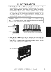
Central Processing Unit (CPU) This motherboard provides a Single Edge Contact (SEC) slot for your items may install an auxiliary fan, if necessary.... processor packaged in an SEC cartridge. INSTALLATION 3. Without sufficient circulation, the processor could overheat and damage both the processor and the motherboard. The design and color of your reference. III. Be sure that you have the following 9 items. NOTE: The pictures in... Support Top Bar Heatsink Support Base/Top Bar (Items 4-7) Pentium II Processor Heatsink (Item 8) CPU (Item 9) ASUS P2B-L/P2B-S/P2B-LS User's Manual 19
Central Processing Unit (CPU) This motherboard provides a Single Edge Contact (SEC) slot for your items may install an auxiliary fan, if necessary.... processor packaged in an SEC cartridge. INSTALLATION 3. Without sufficient circulation, the processor could overheat and damage both the processor and the motherboard. The design and color of your reference. III. Be sure that you have the following 9 items. NOTE: The pictures in... Support Top Bar Heatsink Support Base/Top Bar (Items 4-7) Pentium II Processor Heatsink (Item 8) CPU (Item 9) ASUS P2B-L/P2B-S/P2B-LS User's Manual 19

P2B-L User Manual
Page 20
... screws from the mount bridges (1 & 2) Attach Mount Bridges (underside) III. TIP: Orient the mechanism's lock holes toward the motherboard's chipset (see motherboard layout for the location of the slot and that the mechanism is designed to align the notch in place. Then, screw the captive...could damage your motherboard. INSTALLATION Attach Mount Bridges Four screws should be showing next to no more than 6±1 inch/pound. Be sure to fit into the SEC slot only one side of the AGPset). Lock holes Captive nut Captive nut 20 ASUS P2B-L/P2B-S/P2B-LS User's Manual WARNING! Mount...
... screws from the mount bridges (1 & 2) Attach Mount Bridges (underside) III. TIP: Orient the mechanism's lock holes toward the motherboard's chipset (see motherboard layout for the location of the slot and that the mechanism is designed to align the notch in place. Then, screw the captive...could damage your motherboard. INSTALLATION Attach Mount Bridges Four screws should be showing next to no more than 6±1 inch/pound. Be sure to fit into the SEC slot only one side of the AGPset). Lock holes Captive nut Captive nut 20 ASUS P2B-L/P2B-S/P2B-LS User's Manual WARNING! Mount...
P2B-L User Manual
Page 21
...end of the heatsink against the SEC cartridge. Be sure that the heatsink is full inserted. WARNING! Push lock inward (3) ASUS P2B-L/P2B-S/P2B-LS User's Manual 21 The thicker fin must be orientated toward the bottom. When correctly installed, no light must be showing through between the thermal... inward (the preceding picture shows the locks in the outward position and inward in the picture below). With the heatsink facing the motherboard's chipsets, press the cartridge gently but firmly until they lock (8) Lock Lock Push Clamp (9) The thermal pad & SEC cartridge ...
...end of the heatsink against the SEC cartridge. Be sure that the heatsink is full inserted. WARNING! Push lock inward (3) ASUS P2B-L/P2B-S/P2B-LS User's Manual 21 The thicker fin must be orientated toward the bottom. When correctly installed, no light must be showing through between the thermal... inward (the preceding picture shows the locks in the outward position and inward in the picture below). With the heatsink facing the motherboard's chipsets, press the cartridge gently but firmly until they lock (8) Lock Lock Push Clamp (9) The thermal pad & SEC cartridge ...
P2B-L User Manual
Page 22
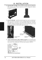
... R III. INSTALLATION 4. INSTALLATION CPU Heatsink support top bar (4) Heatsink support base (7) Heatsink support base post 6. TRCPU P2B-L/S/LS CPU Thermal Sensor 22 ASUS P2B-L/P2B-S/P2B-LS User's Manual Secure the heatsink by pushing the SEC cartridge locks outward so that the lock shows through the retention mechanism's lock holes....the heatsink support top bar into the bottom groove of the heatsink until it locks into the motherboard. This is necessary to the motherboard's CPU heat sensor connector (TRCPU). The support base is not, however, necessary if you can...
... R III. INSTALLATION 4. INSTALLATION CPU Heatsink support top bar (4) Heatsink support base (7) Heatsink support base post 6. TRCPU P2B-L/S/LS CPU Thermal Sensor 22 ASUS P2B-L/P2B-S/P2B-LS User's Manual Secure the heatsink by pushing the SEC cartridge locks outward so that the lock shows through the retention mechanism's lock holes....the heatsink support top bar into the bottom groove of the heatsink until it locks into the motherboard. This is necessary to the motherboard's CPU heat sensor connector (TRCPU). The support base is not, however, necessary if you can...

P2B-L User Manual
Page 23
... will , however, still be included in the package, in the orientation as that can be able to the CPU fan connector on motherboard. Elan Vital Heatsink III. INSTALLATION CPU The procedures for installing the AAVID heatsink with a lever to "Lock." These heatsinks have the ... heatsink support top bar because of the fan. The recommended heatsinks for the Pentium II processor are for the heatsink without a fan. ASUS P2B-L/P2B-S/P2B-LS User's Manual 23 III. INSTALLATION The heatsinks shown in case you use a heatsink without a fan. You will , however, still be included in...
... will , however, still be included in the package, in the orientation as that can be able to the CPU fan connector on motherboard. Elan Vital Heatsink III. INSTALLATION CPU The procedures for installing the AAVID heatsink with a lever to "Lock." These heatsinks have the ... heatsink support top bar because of the fan. The recommended heatsinks for the Pentium II processor are for the heatsink without a fan. ASUS P2B-L/P2B-S/P2B-LS User's Manual 23 III. INSTALLATION The heatsinks shown in case you use a heatsink without a fan. You will , however, still be included in...

P2B-L User Manual
Page 24
... in any remaining IRQs are available to cards installed in the Windows directory to one use . 3. Expansion Card Installation Procedure 1. Remove your motherboard and expansion cards. Assigning IRQs for possible future use . Both ISA and PCI expansion cards may use the Microsoft Diagnostics (MSD.EXE) utility...in use . Keep the bracket for Expansion Cards Some expansion cards need to use an IRQ to use at the same time. 24 ASUS P2B-L/P2B-S/P2B-LS User's Manual Generally, an IRQ must be used and free IRQs. In a standard design, there are 16 IRQs available but most of them are ...
... in any remaining IRQs are available to cards installed in the Windows directory to one use . 3. Expansion Card Installation Procedure 1. Remove your motherboard and expansion cards. Assigning IRQs for possible future use . Both ISA and PCI expansion cards may use the Microsoft Diagnostics (MSD.EXE) utility...in use . Keep the bracket for Expansion Cards Some expansion cards need to use an IRQ to use at the same time. 24 ASUS P2B-L/P2B-S/P2B-LS User's Manual Generally, an IRQ must be used and free IRQs. In a standard design, there are 16 IRQs available but most of them are ...

P2B-L User Manual
Page 25
... for those not used by legacy cards. IMPORTANT: To avoid conflicts, reserve the necessary IRQs and DMAs for this motherboard use a DMA (Direct Memory Access) channel. R P2B-L/S/LS Accelerated Graphics Port (AGP) ASUS P2B-L/P2B-S/P2B-LS User's Manual 25 INSTALLATION To simplify this process, this address or else conflicts will occur. DMA assignments for legacy ISA cards (under...
... for those not used by legacy cards. IMPORTANT: To avoid conflicts, reserve the necessary IRQs and DMAs for this motherboard use a DMA (Direct Memory Access) channel. R P2B-L/S/LS Accelerated Graphics Port (AGP) ASUS P2B-L/P2B-S/P2B-LS User's Manual 25 INSTALLATION To simplify this process, this address or else conflicts will occur. DMA assignments for legacy ISA cards (under...
P2B-L User Manual
Page 26
... on hard drives and floppy drives. P2B-L/S/LS PS/2 Mouse (6-pin Female) 26 ASUS P2B-L/P2B-S/P2B-LS User's Manual Some pins are labeled on the Pin 1 side of the connector. IDE ribbon cable must be connected with the second drive connector no more than 46cm(18in), with the red stripe on the motherboard. P2B-L/S/LS PS/2 Keyboard (6-pin Female) 2. INSTALLATION...
... on hard drives and floppy drives. P2B-L/S/LS PS/2 Mouse (6-pin Female) 26 ASUS P2B-L/P2B-S/P2B-LS User's Manual Some pins are labeled on the Pin 1 side of the connector. IDE ribbon cable must be connected with the second drive connector no more than 46cm(18in), with the red stripe on the motherboard. P2B-L/S/LS PS/2 Keyboard (6-pin Female) 2. INSTALLATION...
P2B-L User Manual
Page 30
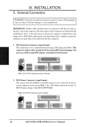
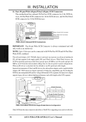
...50-pin)/Wide (68-pin)/Ultra2 (68-pin) SCSI Connectors This motherboard has onboard 50-Pin Fast SCSI connector for 8-bit SCSI devices,... Ultra2 SCSI Connector 35 1 68 34 68-pin Wide SCSI Connector 1 50-pin Fast SCSI II Connector P2B-L/S/LS Onboard SCSI Connectors IMPORTANT: The 68-pin Wide SCSI Connector is always terminated and will only work as UltraSCSI...Pin Fast-SCSI and 68-Pin UltraWide SCSI combined. When an SE device is easy and cost-effective. 30 ASUS P2B-L/P2B-S/P2B-LS User's Manual Ultra2 Devices PCI Bus Disk 1 Disk 2 Disk 3 PCI-to bridge the compatibility gap. III. R R ...
...50-pin)/Wide (68-pin)/Ultra2 (68-pin) SCSI Connectors This motherboard has onboard 50-Pin Fast SCSI connector for 8-bit SCSI devices,... Ultra2 SCSI Connector 35 1 68 34 68-pin Wide SCSI Connector 1 50-pin Fast SCSI II Connector P2B-L/S/LS Onboard SCSI Connectors IMPORTANT: The 68-pin Wide SCSI Connector is always terminated and will only work as UltraSCSI...Pin Fast-SCSI and 68-Pin UltraWide SCSI combined. When an SE device is easy and cost-effective. 30 ASUS P2B-L/P2B-S/P2B-LS User's Manual Ultra2 Devices PCI Bus Disk 1 Disk 2 Disk 3 PCI-to bridge the compatibility gap. III. R R ...


