
P2B-DS User Manual
Page 2
...or missing. Manual revisions are both printed on the following page. For previous or updated manuals, BIOS, drivers, or product release information, contact ASUS at http://www.asus.com.tw or through any means, except documentation kept by the digit before and after the period ... TO CHANGE AT ANY TIME WITHOUT NOTICE, AND SHOULD NOT BE CONSTRUED AS A COMMITMENT BY ASUS. Product Name: ASUS P2B-D/P2B-DS Manual Revision: 1.06 E429 Release Date: July 1999 2 ASUS P2B-D/P2B-DS User's Manual ASUS PROVIDES THIS MANUAL "AS IS" WITHOUT WARRANTY OF ANY KIND, EITHER EXPRESS OR IMPLIED, INCLUDING...
...or missing. Manual revisions are both printed on the following page. For previous or updated manuals, BIOS, drivers, or product release information, contact ASUS at http://www.asus.com.tw or through any means, except documentation kept by the digit before and after the period ... TO CHANGE AT ANY TIME WITHOUT NOTICE, AND SHOULD NOT BE CONSTRUED AS A COMMITMENT BY ASUS. Product Name: ASUS P2B-D/P2B-DS Manual Revision: 1.06 E429 Release Date: July 1999 2 ASUS P2B-D/P2B-DS User's Manual ASUS PROVIDES THIS MANUAL "AS IS" WITHOUT WARRANTY OF ANY KIND, EITHER EXPRESS OR IMPLIED, INCLUDING...
P2B-DS User Manual
Page 4
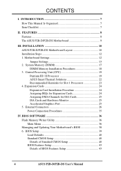
... Writer Utility 36 Main Menu 36 Managing and Updating Your Motherboard's BIOS 38 6. FEATURES 8 Features 8 The ASUS P2B-D/P2B-DS Motherboard 9 III. BIOS Setup 39 Load Defaults 40 Standard CMOS Setup 40 Details of Standard CMOS Setup 40 BIOS Features Setup 43 Details of BIOS Features Setup 43 4 ASUS P2B-D/P2B-DS User's Manual System Memory (DIMM 17 DIMM Memory Installation Procedures...
... Writer Utility 36 Main Menu 36 Managing and Updating Your Motherboard's BIOS 38 6. FEATURES 8 Features 8 The ASUS P2B-D/P2B-DS Motherboard 9 III. BIOS Setup 39 Load Defaults 40 Standard CMOS Setup 40 Details of Standard CMOS Setup 40 BIOS Features Setup 43 Details of BIOS Features Setup 43 4 ASUS P2B-D/P2B-DS User's Manual System Memory (DIMM 17 DIMM Memory Installation Procedures...
P2B-DS User Manual
Page 5
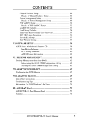
... Motherboard Support CD 58 Installation Submenu 59 DOS Utility Submenu 60 ASUS Contact Information 61 VI. ASUS LAN Card 75 ASUS PCI-L101 Fast Ethernet Card 75 Features 76 ASUS P2B-D/P2B-DS User's Manual 5 ADAPTEC EZ-SCSI 67 Quick Start Instructions 67 Troubleshooting Tips 68 Information for DOS/Windows 3.1x Users 71 ... Power Management Setup 49 Details of Power Management Setup 49 PNP and PCI Setup 52 Details of PNP and PCI Setup 52 Load BIOS Defaults 54 Load Setup Defaults 54 Supervisor Password and User Password 55 IDE HDD Auto Detection 56 Save & Exit Setup 57 Exit ...
... Motherboard Support CD 58 Installation Submenu 59 DOS Utility Submenu 60 ASUS Contact Information 61 VI. ASUS LAN Card 75 ASUS PCI-L101 Fast Ethernet Card 75 Features 76 ASUS P2B-D/P2B-DS User's Manual 5 ADAPTEC EZ-SCSI 67 Quick Start Instructions 67 Troubleshooting Tips 68 Information for DOS/Windows 3.1x Users 71 ... Power Management Setup 49 Details of Power Management Setup 49 PNP and PCI Setup 52 Details of PNP and PCI Setup 52 Load BIOS Defaults 54 Load Setup Defaults 54 Supervisor Password and User Password 55 IDE HDD Auto Detection 56 Save & Exit Setup 57 Exit ...

P2B-DS User Manual
Page 7
...Fast SCSI cable (optional) PS/2 Mouse, Infrared, USB1, and USB2 external connector module (optional) ASUS PCI-L101 Wake-On-LAN 10/100 Ethernet Card (optional) ASUS P2B-D/P2B-DS User's Manual 7 Features Information and specifications III. I . Adaptec EZ-SCSI Adaptec EZ-SCSI utility ...(optional) IX. Installation Setting up the BIOS V. IV. Introduction Manual information and checklist II. Adaptec...
...Fast SCSI cable (optional) PS/2 Mouse, Infrared, USB1, and USB2 external connector module (optional) ASUS PCI-L101 Wake-On-LAN 10/100 Ethernet Card (optional) ASUS P2B-D/P2B-DS User's Manual 7 Features Information and specifications III. I . Adaptec EZ-SCSI Adaptec EZ-SCSI utility ...(optional) IX. Installation Setting up the BIOS V. IV. Introduction Manual information and checklist II. Adaptec...

P2B-DS User Manual
Page 8
... and front-side bus (FSB) platform, which boosts the traditional 66-MHz external bus speed to the memory and processor. 8 ASUS P2B-D/P2B-DS User's Manual These new SDRAMs are carefully designed for high performance, component level interconnect targeted at 3D graphical display applications using a ...100 Fast Ethernet PCI card (see IX. II. FEATURES Features The ASUS P2B-D/P2B-DS motherboards are necessary to meet the enhanced 100MHz bus speed requirement. • Wake-On-LAN: Supports Wake-On-LAN activity through BIOS, which is used to 450MHz) processors. • Intel AGPset: Features...
... and front-side bus (FSB) platform, which boosts the traditional 66-MHz external bus speed to the memory and processor. 8 ASUS P2B-D/P2B-DS User's Manual These new SDRAMs are carefully designed for high performance, component level interconnect targeted at 3D graphical display applications using a ...100 Fast Ethernet PCI card (see IX. II. FEATURES Features The ASUS P2B-D/P2B-DS motherboards are necessary to meet the enhanced 100MHz bus speed requirement. • Wake-On-LAN: Supports Wake-On-LAN activity through BIOS, which is used to 450MHz) processors. • Intel AGPset: Features...

P2B-DS User Manual
Page 10
INSTALLATION ASUS P2B-D/P2B-DS Motherboard Layout PS/2 MOUSE (TOP PORT) KEYBOARD (BOTTOM) CPU_FAN USB USB 1(TOP PORT) USB 2 (BOTTOM) COM 1 COM 2 Slot1 for CPU 2 BUS FREQ Intel 440BX AGPset Multi-I/O Chip SB-LINK™ Connector Hardware Monitor RT2 2Mbit Flash EEPROM (Programmable BIOS) JP4 JP5... Panel Connector ISA Slot 1 ISA Slot 2 NOTE: Grayed items are optional/reserved for CPU 1 III. CLRTC ASUS A97127F Chipset CHA_FAN JP18 CHASSIS EXTBATT IrDA 10 ASUS P2B-D/P2B-DS User's Manual INST ALLATION Motherboard Layout FS0 FS1 FS2 DIMM Socket 3 (64 bit, 168 pin module) DIMM Socket...
INSTALLATION ASUS P2B-D/P2B-DS Motherboard Layout PS/2 MOUSE (TOP PORT) KEYBOARD (BOTTOM) CPU_FAN USB USB 1(TOP PORT) USB 2 (BOTTOM) COM 1 COM 2 Slot1 for CPU 2 BUS FREQ Intel 440BX AGPset Multi-I/O Chip SB-LINK™ Connector Hardware Monitor RT2 2Mbit Flash EEPROM (Programmable BIOS) JP4 JP5... Panel Connector ISA Slot 1 ISA Slot 2 NOTE: Grayed items are optional/reserved for CPU 1 III. CLRTC ASUS A97127F Chipset CHA_FAN JP18 CHASSIS EXTBATT IrDA 10 ASUS P2B-D/P2B-DS User's Manual INST ALLATION Motherboard Layout FS0 FS1 FS2 DIMM Socket 3 (64 bit, 168 pin module) DIMM Socket...
P2B-DS User Manual
Page 12
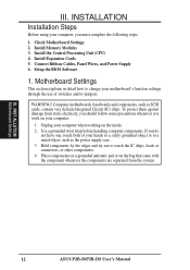
... chips, leads or connectors, or other components. 4. Check Motherboard Settings 2. Use a grounded wrist strap before handling computer components. Setup the BIOS Software 1. III. Install Expansion Cards 5. INST ALLATION Motherboard Settings 12 ASUS P2B-D/P2B-DS User's Manual INSTALLATION Installation Steps Before using your motherboard's function settings through the use of your hands to a safely grounded...
... chips, leads or connectors, or other components. 4. Check Motherboard Settings 2. Use a grounded wrist strap before handling computer components. Setup the BIOS Software 1. III. Install Expansion Cards 5. INST ALLATION Motherboard Settings 12 ASUS P2B-D/P2B-DS User's Manual INSTALLATION Installation Steps Before using your motherboard's function settings through the use of your hands to a safely grounded...

P2B-DS User Manual
Page 13
... (Default) 123 Enable 1 R 1 P2B-D/DS Keyboard Power Up ASUS P2B-D/P2B-DS User's Manual 13 This feature requires an ATX power supply that can supply at least 300mA on your computer. Set to Enable if you want to disable or enable the keyboard power up your computer, (4) Hold down during bootup and enter BIOS setup to re...
... (Default) 123 Enable 1 R 1 P2B-D/DS Keyboard Power Up ASUS P2B-D/P2B-DS User's Manual 13 This feature requires an ATX power supply that can supply at least 300mA on your computer. Set to Enable if you want to disable or enable the keyboard power up your computer, (4) Hold down during bootup and enter BIOS setup to re...

P2B-DS User Manual
Page 17
...double-sided come in IV. INSTALLATION 2. System Memory (DIMM) This motherboard uses only Dual Inline Memory Modules (DIMMs). BIOS SOFTWARE. One side (with 9 chips per side (standard 8 chips/side + 1 ECC chip) and make the ... memory chips are supported: SDRAM with higher pin density than EDO (Extended Data Output) chips. • BIOS shows SDRAM memory on the motherboard. General DIMM Notes • Use only PC100-compliant DIMMs. This motherboard ... memory. Install memory in 32, 64, 128, 256MB. ASUS P2B-D/P2B-DS User's Manual 17 INST ALLATION System Memory III.
...double-sided come in IV. INSTALLATION 2. System Memory (DIMM) This motherboard uses only Dual Inline Memory Modules (DIMMs). BIOS SOFTWARE. One side (with 9 chips per side (standard 8 chips/side + 1 ECC chip) and make the ... memory chips are supported: SDRAM with higher pin density than EDO (Extended Data Output) chips. • BIOS shows SDRAM memory on the motherboard. General DIMM Notes • Use only PC100-compliant DIMMs. This motherboard ... memory. Install memory in 32, 64, 128, 256MB. ASUS P2B-D/P2B-DS User's Manual 17 INST ALLATION System Memory III.

P2B-DS User Manual
Page 24
...ALLATION Expansion Cards III. INSTALLATION 4. Failure to both your used , leaving 5 IRQs free. Carefully align the card's connectors and press firmly. 4. Set up the BIOS if necessary (such as legacy ISA cards, requires that no two devices use . In a standard design, there are 16 IRQs available but most of them...use IRQs. Both ISA and PCI expansion cards may cause severe damage to do so may require the use at the same time. 24 ASUS P2B-D/P2B-DS User's Manual Keep the bracket for your computer will be exclusively assigned to one use an IRQ to use the same IRQ or your ...
...ALLATION Expansion Cards III. INSTALLATION 4. Failure to both your used , leaving 5 IRQs free. Carefully align the card's connectors and press firmly. 4. Set up the BIOS if necessary (such as legacy ISA cards, requires that no two devices use . In a standard design, there are 16 IRQs available but most of them...use IRQs. Both ISA and PCI expansion cards may cause severe damage to do so may require the use at the same time. 24 ASUS P2B-D/P2B-DS User's Manual Keep the bracket for your computer will be exclusively assigned to one use an IRQ to use the same IRQ or your ...

P2B-DS User Manual
Page 25
...something called the INT (interrupt) assignment. DMA assignments for those available. The PCI and PnP configuration of the BIOS setup utility can select a DMA channel in IRQ xx Used By ISA and DMA x Used By ISA ...to PnP cards from those IRQs and DMAs you want to support a new generation of the BIOS Setup utility. IMPORTANT: To avoid conflicts, reserve the necessary IRQs and DMAs for legacy ISA cards (under...ISA cards installed, IRQs are handled the same way as the ASUS AGP-V2740 3D Multimedia Accelerator. 1 R 1 P2B-D/DS Accelerated Graphics Port (AGP) ASUS P2B-D/P2B-DS User's Manual 25
...something called the INT (interrupt) assignment. DMA assignments for those available. The PCI and PnP configuration of the BIOS setup utility can select a DMA channel in IRQ xx Used By ISA and DMA x Used By ISA ...to PnP cards from those IRQs and DMAs you want to support a new generation of the BIOS Setup utility. IMPORTANT: To avoid conflicts, reserve the necessary IRQs and DMAs for legacy ISA cards (under...ISA cards installed, IRQs are handled the same way as the ASUS AGP-V2740 3D Multimedia Accelerator. 1 R 1 P2B-D/DS Accelerated Graphics Port (AGP) ASUS P2B-D/P2B-DS User's Manual 25

P2B-DS User Manual
Page 26
... will not allow standard AT size (large DIN) keyboard plugs. You may be connected with the second drive connector no more than 15 cm (6 in BIOS Features Setup of the BIOS SOFTWARE. PS/2 Mouse (6-pin Female) 26 ASUS P2B-D/P2B-DS User's Manual III.
... will not allow standard AT size (large DIN) keyboard plugs. You may be connected with the second drive connector no more than 15 cm (6 in BIOS Features Setup of the BIOS SOFTWARE. PS/2 Mouse (6-pin Female) 26 ASUS P2B-D/P2B-DS User's Manual III.

P2B-DS User Manual
Page 27
...Ports (9-pin Male) 5. Parallel Printer Connector (25-pin Female) You can be connected to Pin 1 Pin 1 Floppy Drive Connector P2B-D/DS Floppy Disk Drive Connector ASUS P2B-D/P2B-DS User's Manual 27 See "Onboard Serial Port..." Floppy Disk Drive Connector (34-1pin FLOPPY) This connector supports the provided floppy disk drive... cables with pin 5 plugged). 1 R 1 NOTE: Orient the red stripe on the other serial devices. in Chipset Features Setup of the BIOS SOFTWARE. III. NOTE: Serial printers must be used for pointing devices or other end to the floppy drives. (Pin 5 is removed to...
...Ports (9-pin Male) 5. Parallel Printer Connector (25-pin Female) You can be connected to Pin 1 Pin 1 Floppy Drive Connector P2B-D/DS Floppy Disk Drive Connector ASUS P2B-D/P2B-DS User's Manual 27 See "Onboard Serial Port..." Floppy Disk Drive Connector (34-1pin FLOPPY) This connector supports the provided floppy disk drive... cables with pin 5 plugged). 1 R 1 NOTE: Orient the red stripe on the other serial devices. in Chipset Features Setup of the BIOS SOFTWARE. III. NOTE: Serial printers must be used for pointing devices or other end to the floppy drives. (Pin 5 is removed to...

P2B-DS User Manual
Page 28
... you must configure the second drive to prevent inserting in the BIOS Features Setup of your hard disk(s). Please refer to Pin 1 Primary IDE Connector PIN 1 P2B-D/DS IDE Connectors Secondary IDE Connector 28 ASUS P2B-D/P2B-DS User's Manual NOTE: Orient the red stripe on a SCSI ...drive and select the boot disk through BIOS Features Setup. USB 1 Universal Serial Bus (USB) 2 7. BIOS now supports SCSI device or IDE CD-...
... you must configure the second drive to prevent inserting in the BIOS Features Setup of your hard disk(s). Please refer to Pin 1 Primary IDE Connector PIN 1 P2B-D/DS IDE Connectors Secondary IDE Connector 28 ASUS P2B-D/P2B-DS User's Manual NOTE: Orient the red stripe on a SCSI ...drive and select the boot disk through BIOS Features Setup. USB 1 Universal Serial Bus (USB) 2 7. BIOS now supports SCSI device or IDE CD-...

P2B-DS User Manual
Page 31
... ATX power supply with at least 720mA +5-volt standby power P2B-D/DS Wake on LAN Connector 13. This occurs when the side panel is available only with a Wake-On-LAN output, such as the ASUS PCI-L101 (see "Power Management Setup" under IV. BIOS SOFTWARE) and that the Wake-On-LAN Power Up Control...
... ATX power supply with at least 720mA +5-volt standby power P2B-D/DS Wake on LAN Connector 13. This occurs when the side panel is available only with a Wake-On-LAN output, such as the ASUS PCI-L101 (see "Power Management Setup" under IV. BIOS SOFTWARE) and that the Wake-On-LAN Power Up Control...

P2B-DS User Manual
Page 32
... V MSG.LED ExtSMI# Ground PWR_SW +3VSB ResetCon Ground MSG LED Reset SW SMI Lead ATX Power Switch* P2B-D/DS System Panel Connections * Requires an ATX power supply. 32 ASUS P2B-D/P2B-DS User's Manual If you do not have a switch for rebooting your computer without having to open moment and ...therefore leaving it detects a short to turn the system off your BIOS or OS setting. This 2-pin connector connects to...
... V MSG.LED ExtSMI# Ground PWR_SW +3VSB ResetCon Ground MSG LED Reset SW SMI Lead ATX Power Switch* P2B-D/DS System Panel Connections * Requires an ATX power supply. 32 ASUS P2B-D/P2B-DS User's Manual If you do not have a switch for rebooting your computer without having to open moment and ...therefore leaving it detects a short to turn the system off your BIOS or OS setting. This 2-pin connector connects to...

P2B-DS User Manual
Page 35
.... While the tests are made, close the system case cover. 2. Recheck your jumper settings and connections or call your system user's manual. 4. ASUS P2B-D/P2B-DS User's Manual 35 III. Be sure that is pressed. Your system power. For ATX power supplies, the system LED will light when the ATX ... failed a power-on the front of the case. 6. The power LED on your devices in the next section, BIOS SOFTWARE. * Powering Off your system case according to enter BIOS setup. For ATX power supplies, you use Windows 95, click the Start button, click Shut Down, and then click...
.... While the tests are made, close the system case cover. 2. Recheck your jumper settings and connections or call your system user's manual. 4. ASUS P2B-D/P2B-DS User's Manual 35 III. Be sure that is pressed. Your system power. For ATX power supplies, the system LED will light when the ATX ... failed a power-on the front of the case. 6. The power LED on your devices in the next section, BIOS SOFTWARE. * Powering Off your system case according to enter BIOS setup. For ATX power supplies, you use Windows 95, click the Start button, click Shut Down, and then click...

P2B-DS User Manual
Page 36
.... If "unknown" is displayed after Flash Memory:, the memory chip is either not programmable or is recommended that updates the BIOS by the Flash Memory Writer utility. NOTE: The following screen displays are provided as examples only and may not reflect the ...BIOS and therefore, cannot be programmed by uploading a new BIOS file to save your system. To determine the BIOS version of your motherboard, check the last four numbers of the original motherboard BIOS in DOS mode. IV. Type a filename and the path, for example, A:\440BX-1 and then press . 36 ASUS P2B-D/P2B-DS...
.... If "unknown" is displayed after Flash Memory:, the memory chip is either not programmable or is recommended that updates the BIOS by the Flash Memory Writer utility. NOTE: The following screen displays are provided as examples only and may not reflect the ...BIOS and therefore, cannot be programmed by uploading a new BIOS file to save your system. To determine the BIOS version of your motherboard, check the last four numbers of the original motherboard BIOS in DOS mode. IV. Type a filename and the path, for example, A:\440BX-1 and then press . 36 ASUS P2B-D/P2B-DS...

P2B-DS User Manual
Page 37
..., for procedures on downloading an updated BIOS file. When prompted to confirm the BIOS update, press Y to program the new BIOS information into the flash ROM. The utility starts to start the update. Follow the onscreen instructions to continue. BIOS Flash Memory Writer ASUS P2B-D/P2B-DS User's Manual 37 The Update BIOS Including Boot Block and ESCD screen...
..., for procedures on downloading an updated BIOS file. When prompted to confirm the BIOS update, press Y to program the new BIOS information into the flash ROM. The utility starts to start the update. Follow the onscreen instructions to continue. BIOS Flash Memory Writer ASUS P2B-D/P2B-DS User's Manual 37 The Update BIOS Including Boot Block and ESCD screen...

P2B-DS User Manual
Page 38
... . 4. IV. Copy AFLASH.EXE to File. See 1. Save Current BIOS To File on the previous page for more details and the rest of the steps. Boot from the disk you created earlier. 2. BIOS Updating BIOS 38 ASUS P2B-D/P2B-DS User's Manual At the Main Menu, type 2 and then press . ...See 2. Download an updated ASUS BIOS file from booting up . If the Flash Memory Writer utility was not able to ...
... . 4. IV. Copy AFLASH.EXE to File. See 1. Save Current BIOS To File on the previous page for more details and the rest of the steps. Boot from the disk you created earlier. 2. BIOS Updating BIOS 38 ASUS P2B-D/P2B-DS User's Manual At the Main Menu, type 2 and then press . ...See 2. Download an updated ASUS BIOS file from booting up . If the Flash Memory Writer utility was not able to ...


