
P2B-B User Manual
Page 2
...DAMAGES ARISING FROM ANY DEFECT OR ERROR IN THIS MANUAL OR PRODUCT. For previous or updated manuals, BIOS, drivers, or product release information, contact ASUS at http://www.asus.com.tw or through any means, except documentation kept by the purchaser for backup purposes, without ...the third digit in the manual revision number. or (2) the serial number of the manual revision number. Product Name: ASUS P2B-B Manual Revision: 1.02 E309 Release Date: December1998 2 ASUS P2B-B User's Manual USER'S NOTICE No part of this manual may or may be reproduced, transmitted, transcribed, stored in ...
...DAMAGES ARISING FROM ANY DEFECT OR ERROR IN THIS MANUAL OR PRODUCT. For previous or updated manuals, BIOS, drivers, or product release information, contact ASUS at http://www.asus.com.tw or through any means, except documentation kept by the purchaser for backup purposes, without ...the third digit in the manual revision number. or (2) the serial number of the manual revision number. Product Name: ASUS P2B-B Manual Revision: 1.02 E309 Release Date: December1998 2 ASUS P2B-B User's Manual USER'S NOTICE No part of this manual may or may be reproduced, transmitted, transcribed, stored in ...
P2B-B User Manual
Page 4
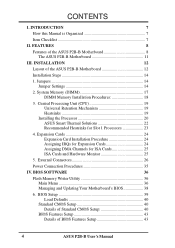
... 4. CONTENTS I. External Connectors 26 Power Connection Procedures 35 IV. BIOS Setup 39 Load Defaults 40 Standard CMOS Setup 40 Details of Standard CMOS Setup 40 BIOS Features Setup 43 Details of the ASUS P2B-B Motherboard 12 Installation Steps 14 1. FEATURES 8 Features of the ASUS P2B-B Motherboard 8 The ASUS P2B-B Motherboard 11 III. Central Processing Unit (CPU 19 Universal...
... 4. CONTENTS I. External Connectors 26 Power Connection Procedures 35 IV. BIOS Setup 39 Load Defaults 40 Standard CMOS Setup 40 Details of Standard CMOS Setup 40 BIOS Features Setup 43 Details of the ASUS P2B-B Motherboard 12 Installation Steps 14 1. FEATURES 8 Features of the ASUS P2B-B Motherboard 8 The ASUS P2B-B Motherboard 11 III. Central Processing Unit (CPU 19 Universal...

P2B-B User Manual
Page 5
...Management Interface (DMI 59 Introducing the ASUS DMI Configuration Utility 59 System Requirements 59 Using the ASUS DMI Configuration Utility 60 VI. ASUS LAN Card 63 ASUS PCI-L101 Fast Ethernet Card 63 Features 64 Software Driver Support 64 Question and Answer 64 ASUS P2B-B User's Manual 5 CONTENTS Chipset ...Features Setup 46 Details of Chipset Features Setup 46 Power Management Setup 49 Details of Power Management Setup 49 PNP and PCI Setup 52 Details of PNP and PCI Setup 52 Load BIOS Defaults 54 Load ...
...Management Interface (DMI 59 Introducing the ASUS DMI Configuration Utility 59 System Requirements 59 Using the ASUS DMI Configuration Utility 60 VI. ASUS LAN Card 63 ASUS PCI-L101 Fast Ethernet Card 63 Features 64 Software Driver Support 64 Question and Answer 64 ASUS P2B-B User's Manual 5 CONTENTS Chipset ...Features Setup 46 Details of Chipset Features Setup 46 Power Management Setup 49 Details of Power Management Setup 49 PNP and PCI Setup 52 Details of PNP and PCI Setup 52 Load BIOS Defaults 54 Load ...

P2B-B User Manual
Page 7
...Instructions on setting up the motherboard and jumpers Instructions on setting up the BIOS software Information on the included support software Item Checklist Please check that your retailer. (1) ASUS Motherboard (1) Universal Retention Mechanism for SECC/SECC2/SEPP (1) IDE ribbon ...(1) Motherboard User's manual Infrared module (optional) USB/MIR module (optional) ASUS PCI-L101 Wake-On-LAN 10/100 Ethernet Card (optional) ASUS PC100-compliant SDRAM (optional) ASUS P2B-B User's Manual 7 BIOS Software: V. Features: III. Support CD: Manual information and checklist Information and...
...Instructions on setting up the motherboard and jumpers Instructions on setting up the BIOS software Information on the included support software Item Checklist Please check that your retailer. (1) ASUS Motherboard (1) Universal Retention Mechanism for SECC/SECC2/SEPP (1) IDE ribbon ...(1) Motherboard User's manual Infrared module (optional) USB/MIR module (optional) ASUS PCI-L101 Wake-On-LAN 10/100 Ethernet Card (optional) ASUS PC100-compliant SDRAM (optional) ASUS P2B-B User's Manual 7 BIOS Software: V. Features: III. Support CD: Manual information and checklist Information and...
P2B-B User Manual
Page 9
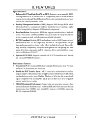
...and Plug and Play devices to upgrade current hard drives or cables. • SDRAM Optimized Performance: Supports the new generation memory - ASUS P2B-B User's Manual 9 Performance Features: • Concurrent PCI: Concurrent PCI allows multiple PCI transfers from 528MB/s max using EDO memory to...Access Memory (SDRAM) which allows hardware to 33MB/s. FEATURES Special Features: • Enhanced ACPI and Anti-Boot Virus BIOS: Features a programmable BIOS, offering enhanced ACPI for Windows 98 compatibility, built-in firmware-based virus protection through Trend ChipAway Virus codes, and ...
...and Plug and Play devices to upgrade current hard drives or cables. • SDRAM Optimized Performance: Supports the new generation memory - ASUS P2B-B User's Manual 9 Performance Features: • Concurrent PCI: Concurrent PCI allows multiple PCI transfers from 528MB/s max using EDO memory to...Access Memory (SDRAM) which allows hardware to 33MB/s. FEATURES Special Features: • Enhanced ACPI and Anti-Boot Virus BIOS: Features a programmable BIOS, offering enhanced ACPI for Windows 98 compatibility, built-in firmware-based virus protection through Trend ChipAway Virus codes, and ...

P2B-B User Manual
Page 10
...8226; Keyboard Power Up: Keyboard Power Up can be enabled or disabled to allow the computer to ensure proper system configuration and management. 10 ASUS P2B-B User's Manual Through the way a particular LED illuminates, the user can access vital information from their limited resources more efficiently. •...sensors to monitor the CPU (the Pentium II processor requires a special heatsink with a thermal sensor) and system temperatures to warn of the BIOS setting. • Fan Status Monitoring and Alarm: To prevent system overheat and system damage, the CPU fan and system fans can be ...
...8226; Keyboard Power Up: Keyboard Power Up can be enabled or disabled to allow the computer to ensure proper system configuration and management. 10 ASUS P2B-B User's Manual Through the way a particular LED illuminates, the user can access vital information from their limited resources more efficiently. •...sensors to monitor the CPU (the Pentium II processor requires a special heatsink with a thermal sensor) and system temperatures to warn of the BIOS setting. • Fan Status Monitoring and Alarm: To prevent system overheat and system damage, the CPU fan and system fans can be ...

P2B-B User Manual
Page 12
INSTALLATION Layout of the ASUS P2B-B Motherboard ISA Slot 2 ISA Slot 1 PCI Slot 3 (PCI3) CPU Slot 1 PS/2 Hardware Monitor Super Multi I/O SBLINK USB/MIR PARALLEL WOL_CON Wake-On-LAN Connector FLOPPY ...-bit, 168-pin module) DIMM Socket 2 (64/72-bit, 168-pin module) DIMM Socket 3 (64/72-bit, 168-pin module) Intel PIIX4 PCIset CLRTC ASUS ASIC SMB BIOS Power CR2032 3V Lithium Cell Intel 440BX AGPset PRIMARY IDE SECONDARY IDE FS0 FS1 FS2 FS3 FREQ MULT BF0 IR BF1 BF2 BF3 PANEL...
INSTALLATION Layout of the ASUS P2B-B Motherboard ISA Slot 2 ISA Slot 1 PCI Slot 3 (PCI3) CPU Slot 1 PS/2 Hardware Monitor Super Multi I/O SBLINK USB/MIR PARALLEL WOL_CON Wake-On-LAN Connector FLOPPY ...-bit, 168-pin module) DIMM Socket 2 (64/72-bit, 168-pin module) DIMM Socket 3 (64/72-bit, 168-pin module) Intel PIIX4 PCIset CLRTC ASUS ASIC SMB BIOS Power CR2032 3V Lithium Cell Intel 440BX AGPset PRIMARY IDE SECONDARY IDE FS0 FS1 FS2 FS3 FREQ MULT BF0 IR BF1 BF2 BF3 PANEL...

P2B-B User Manual
Page 14
...your hands to a safely grounded object or to reenter user preferences. RTC RAMCLRTC Clear Data [short solder points momentarily] CLRTC P2B-B Clear RTC RAM 14 ASUS P2B-B User's Manual Connect Ribbon Cables, Cabinet Wires, and Power Supply 6. Jumper Settings 1. Set Jumpers 2. Jumpers WARNING! To... system. To clear the RTC data: (1) Unplug your computer, (4) Hold down during bootup and enter BIOS setup to a metal object, such as the power supply case. 3. III. Setup the BIOS Software 1. Unplug your computer when working on your computer, (2) Short solder points, (3) Turn on the...
...your hands to a safely grounded object or to reenter user preferences. RTC RAMCLRTC Clear Data [short solder points momentarily] CLRTC P2B-B Clear RTC RAM 14 ASUS P2B-B User's Manual Connect Ribbon Cables, Cabinet Wires, and Power Supply 6. Jumper Settings 1. Set Jumpers 2. Jumpers WARNING! To... system. To clear the RTC data: (1) Unplug your computer, (4) Hold down during bootup and enter BIOS setup to a metal object, such as the power supply case. 3. III. Setup the BIOS Software 1. Unplug your computer when working on your computer, (2) Short solder points, (3) Turn on the...

P2B-B User Manual
Page 15
... is set this to power up function. Setting Disable Enable KBPWR [1-2] (default) [2-3] KBPWR 1 2 3 Disable (Default) KBPWR 1 2 3 Enable P2B-B Keyboard Power Up 3. Voltage Input/Output Selection (VIO) This jumper allows you to enable or disable the keyboard power up your keyboard (by pressing the...ATX power supply that can supply at least 300mA on the +5VSB lead and new BIOS support. INSTALLATION Jumpers R R 1 2 3 VIO 3.50Volts (Default) 1 2 3 3.66Volts P2B-B Voltage Input/Output Selection ASUS P2B-B User's Manual 15 Set to Enable if you set to use your system. Your...
... is set this to power up function. Setting Disable Enable KBPWR [1-2] (default) [2-3] KBPWR 1 2 3 Disable (Default) KBPWR 1 2 3 Enable P2B-B Keyboard Power Up 3. Voltage Input/Output Selection (VIO) This jumper allows you to enable or disable the keyboard power up your keyboard (by pressing the...ATX power supply that can supply at least 300mA on the +5VSB lead and new BIOS support. INSTALLATION Jumpers R R 1 2 3 VIO 3.50Volts (Default) 1 2 3 3.66Volts P2B-B Voltage Input/Output Selection ASUS P2B-B User's Manual 15 Set to Enable if you set to use your system. Your...

P2B-B User Manual
Page 17
Memory speed setup is recommended through "Chipset Features Setup" in BIOS setup. ASUS P2B-B User's Manual 17 System Memory (DIMM) This motherboard uses only Dual Inline Memory Modules (DIMMs). Install memory in 16, 32, 64,128MB; This motherboard ... not support ECC, only 9 chips/side modules support ECC. • Single-sided DIMMs come in BIOS setup. If your DIMMs are generally thinner with higher pin density than EDO (Extended Data Output) chips. • BIOS shows SDRAM memory on the motherboard. III. Sockets are available for system stability. • Two possible...
Memory speed setup is recommended through "Chipset Features Setup" in BIOS setup. ASUS P2B-B User's Manual 17 System Memory (DIMM) This motherboard uses only Dual Inline Memory Modules (DIMMs). Install memory in 16, 32, 64,128MB; This motherboard ... not support ECC, only 9 chips/side modules support ECC. • Single-sided DIMMs come in BIOS setup. If your DIMMs are generally thinner with higher pin density than EDO (Extended Data Output) chips. • BIOS shows SDRAM memory on the motherboard. III. Sockets are available for system stability. • Two possible...

P2B-B User Manual
Page 24
...click the System icon under Device Manager displays the resource settings being used by a particular device (to use at the same time. 24 ASUS P2B-B User's Manual Ensure that you removed above. 5. Read the documentation for your expansion card and make any necessary hardware or software settings ...for expansion cards. III. Failure to operate. Set up the BIOS if necessary (such as IRQ xx Used By ISA: Yes in any remaining IRQs are two types of your motherboard and expansion cards. ...
...click the System icon under Device Manager displays the resource settings being used by a particular device (to use at the same time. 24 ASUS P2B-B User's Manual Ensure that you removed above. 5. Read the documentation for your expansion card and make any necessary hardware or software settings ...for expansion cards. III. Failure to operate. Set up the BIOS if necessary (such as IRQ xx Used By ISA: Yes in any remaining IRQs are two types of your motherboard and expansion cards. ...

P2B-B User Manual
Page 25
INSTALLATION DMA Channels III. R P2B-B Accelerated Graphics Port (AGP) ASUS P2B-B User's Manual 25 III. For older Legacy cards that the ...INSTALLATION To simplify this process this address or else conflicts will occur. In the PCI bus design, the BIOS automatically assigns an IRQ to the system. You can be sure that does not work with ultra-high...INT A. If the system has both legacy and PnP, may also need to support a new generation of the BIOS Setup utility. To install a PCI card, you want to indicate which was developed to allow automatic system configuration...
INSTALLATION DMA Channels III. R P2B-B Accelerated Graphics Port (AGP) ASUS P2B-B User's Manual 25 III. For older Legacy cards that the ...INSTALLATION To simplify this process this address or else conflicts will occur. In the PCI bus design, the BIOS automatically assigns an IRQ to the system. You can be sure that does not work with ultra-high...INT A. If the system has both legacy and PnP, may also need to support a new generation of the BIOS Setup utility. To install a PCI card, you want to indicate which was developed to allow automatic system configuration...

P2B-B User Manual
Page 27
... These connectors support the provided serial port ribbon cables with mounting bracket. COM 1 Pin 1 COM 2 Pin 1 R R P2B-B Serial Port Connectors ASUS P2B-B User's Manual 27 Parallel Printer Connector (26-1 pin PARALLEL) This connector supports the included parallel port ribbon cable with mounting ...bracket. NOTE: Serial printers must be connected to prevent inserting in Chipset Features of the BIOS SOFTWARE. (...
... These connectors support the provided serial port ribbon cables with mounting bracket. COM 1 Pin 1 COM 2 Pin 1 R R P2B-B Serial Port Connectors ASUS P2B-B User's Manual 27 Parallel Printer Connector (26-1 pin PARALLEL) This connector supports the included parallel port ribbon cable with mounting ...bracket. NOTE: Serial printers must be connected to prevent inserting in Chipset Features of the BIOS SOFTWARE. (...

P2B-B User Manual
Page 28
...pin 1 6. IDE activity LED (2-pin IDELED) This connector supplies power to be both Masters using ribbon cables with pin 20 plugged). P2B-B IDE Activity LED IDELED 28 ASUS P2B-B User's Manual Pin 1 R III. III. If you install two hard disks, you must configure the second drive to Slave ... supports SCSI device or IDE CD-ROM bootup (see "HDD Sequence SCSI/IDE First" & "Boot Sequence" in the BIOS Features Setup. INSTALLATION Connectors P2B-B IDE Connectors Secondary IDE Connector Primary IDE Connector NOTE: Orient the red markings (usually zigzag) on each IDE drive and ...
...pin 1 6. IDE activity LED (2-pin IDELED) This connector supplies power to be both Masters using ribbon cables with pin 20 plugged). P2B-B IDE Activity LED IDELED 28 ASUS P2B-B User's Manual Pin 1 R III. III. If you install two hard disks, you must configure the second drive to Slave ... supports SCSI device or IDE CD-ROM bootup (see "HDD Sequence SCSI/IDE First" & "Boot Sequence" in the BIOS Features Setup. INSTALLATION Connectors P2B-B IDE Connectors Secondary IDE Connector Primary IDE Connector NOTE: Orient the red markings (usually zigzag) on each IDE drive and ...

P2B-B User Manual
Page 29
... This feature requires that your system has an ATX power supply with at least 720mA +5V standby power. +5 VSB PME Ground R P2B-B Wake-On-LAN Connector ASUS P2B-B User's Manual 29 The LAN card powers up the system when a wakeup packet or signal is set to a LAN card with... the black should be used . Wake-On-LAN Connector (3-pin WOL_CON) This connector connects to Enabled (see "Power Management Setup" under BIOS SOFTWARE section) and that the WAKE On LAN Power Up Control is received from the network. Chassis,CPU,&PowerSupplyFanConnectors(3-pinCHA_,CPU_,PWR_FAN) These connectors...
... This feature requires that your system has an ATX power supply with at least 720mA +5V standby power. +5 VSB PME Ground R P2B-B Wake-On-LAN Connector ASUS P2B-B User's Manual 29 The LAN card powers up the system when a wakeup packet or signal is set to a LAN card with... the black should be used . Wake-On-LAN Connector (3-pin WOL_CON) This connector connects to Enabled (see "Power Management Setup" under BIOS SOFTWARE section) and that the WAKE On LAN Power Up Control is received from the network. Chassis,CPU,&PowerSupplyFanConnectors(3-pinCHA_,CPU_,PWR_FAN) These connectors...

P2B-B User Manual
Page 30
... Keylock Ground +5V Ground Ground Speaker +5 V TB_LED ExtSMI# Ground PWR +3VSB Reset Ground P2B-B System Panel Connections Message LED SMI Lead Reset SW ATX Power Switch* * Requires an ATX power supply. 30 ASUS P2B-B User's Manual This function requires ACPI OS support. 10. INSTALLATION 9. This 2-pin connector ...wakeup (the SMI lead cannot wake-up can be controlled by a momentary switch connected to this connector, "Suspend Switch" in the BIOS but the keyboard will be on the position of Enable. 11. Keyboard Lock Switch Lead (2-pin KEYLOCK) This 2-pin connector connects ...
... Keylock Ground +5V Ground Ground Speaker +5 V TB_LED ExtSMI# Ground PWR +3VSB Reset Ground P2B-B System Panel Connections Message LED SMI Lead Reset SW ATX Power Switch* * Requires an ATX power supply. 30 ASUS P2B-B User's Manual This function requires ACPI OS support. 10. INSTALLATION 9. This 2-pin connector ...wakeup (the SMI lead cannot wake-up can be controlled by a momentary switch connected to this connector, "Suspend Switch" in the BIOS but the keyboard will be on the position of Enable. 11. Keyboard Lock Switch Lead (2-pin KEYLOCK) This 2-pin connector connects ...

P2B-B User Manual
Page 31
...configure the setting through "UART2 Use Infrared" in PnP and PCI Setup of the BIOS SOFTWARE. R R (NC) GND Front View Back View +5V IRRX IRTX P2B-B Infrared Module Connector IRTX GND IRRX +5V (NC) ASUS P2B-B User's Manual 31 USB, Infrared, PS/2 Mouse Module Connector (18-1 pin USB... infrared module connector (5-pin IR) This connector supports the optional wireless transmitting and receiving infrared module. See PS/2 Mouse Control in BIOS Features Setup and USB Function in Chipset Features Setup to the pin definitions. This module mounts to a small opening on the Back...
...configure the setting through "UART2 Use Infrared" in PnP and PCI Setup of the BIOS SOFTWARE. R R (NC) GND Front View Back View +5V IRRX IRTX P2B-B Infrared Module Connector IRTX GND IRRX +5V (NC) ASUS P2B-B User's Manual 31 USB, Infrared, PS/2 Mouse Module Connector (18-1 pin USB... infrared module connector (5-pin IR) This connector supports the optional wireless transmitting and receiving infrared module. See PS/2 Mouse Control in BIOS Features Setup and USB Function in Chipset Features Setup to the pin definitions. This module mounts to a small opening on the Back...

P2B-B User Manual
Page 35
.... The monitor LED may have failed a power-on tests. Recheck your jumper settings and connections or call your devices in the next section, BIOS SOFTWARE. * Powering Off your computer: You must first exit or shut down your operating system. Be sure that is pressed. Your monitor ...power supplies, the system LED will light when the ATX power switch is equipped with ). 3. Follow the instructions in the following order: a. ASUS P2B-B User's Manual 35 After all switches are off your system user's manual. 4. The system will not appear when shutting down your operating ...
.... The monitor LED may have failed a power-on tests. Recheck your jumper settings and connections or call your devices in the next section, BIOS SOFTWARE. * Powering Off your computer: You must first exit or shut down your operating system. Be sure that is pressed. Your monitor ...power supplies, the system LED will light when the ATX power switch is equipped with ). 3. Follow the instructions in the following order: a. ASUS P2B-B User's Manual 35 After all switches are off your system user's manual. 4. The system will not appear when shutting down your operating ...

P2B-B User Manual
Page 36
... last four numbers of the code displayed on the upper left-hand corner of the original motherboard BIOS in DOS mode. Type a filename and the path, for example, A:\XXX-X and then press . 36 ASUS P2B-B User's Manual If "unknown" is displayed after Flash Memory:, the memory chip is either not... programmable or is recommended that updates the BIOS by the Flash Memory Writer utility. To save AFLASH.EXE and the BIOS file to the programmable flash ROM chip on...
... last four numbers of the code displayed on the upper left-hand corner of the original motherboard BIOS in DOS mode. Type a filename and the path, for example, A:\XXX-X and then press . 36 ASUS P2B-B User's Manual If "unknown" is displayed after Flash Memory:, the memory chip is either not... programmable or is recommended that updates the BIOS by the Flash Memory Writer utility. To save AFLASH.EXE and the BIOS file to the programmable flash ROM chip on...

P2B-B User Manual
Page 37
... continue. When the programming is finished, Flashed Successfully will be displayed. BIOS Flash Memory Writer ASUS P2B-B User's Manual 37 The Update BIOS Including Boot Block and ESCD screen appears. When prompted to confirm the BIOS update, press Y to start the update. Update BIOS Including Boot Block and ESCD This option updates the boot block, the...
... continue. When the programming is finished, Flashed Successfully will be displayed. BIOS Flash Memory Writer ASUS P2B-B User's Manual 37 The Update BIOS Including Boot Block and ESCD screen appears. When prompted to confirm the BIOS update, press Y to start the update. Update BIOS Including Boot Block and ESCD This option updates the boot block, the...


