P2B-B User Manual
Page 16
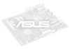
... (BF0, BF1, BF2, BF3) These jumpers set together with the above 100MHz exceed the specifications for the on- board Intel Chipset and are not guaranteed to the onboard power controller. 16 ASUS P2B-B User's Manual CPU to the CPU. Frequencies above jumpers CPU External (BUS) Frequency Selection. 123 123 123 123... 1 2 3 CPU120.0MHz PCI 40.0MHz FS3 FS2 FS1 FS0 FS3 FS2 FS1 FS0 FS3 FS2 FS1 FS0 FS3 FS2 FS1 FS0 FS3 FS2 FS1 FS0 P2B-B CPU Settings 1 1 2 2 3 3 CPU 124.0MHz CPU 133.0MHz PCI 31.0MHz PCI 44.3MHz CPU Bus Frequency 1 2 3 CPU133.0MHz PCI 33.3MHz 1 2 3 ...
... (BF0, BF1, BF2, BF3) These jumpers set together with the above 100MHz exceed the specifications for the on- board Intel Chipset and are not guaranteed to the onboard power controller. 16 ASUS P2B-B User's Manual CPU to the CPU. Frequencies above jumpers CPU External (BUS) Frequency Selection. 123 123 123 123... 1 2 3 CPU120.0MHz PCI 40.0MHz FS3 FS2 FS1 FS0 FS3 FS2 FS1 FS0 FS3 FS2 FS1 FS0 FS3 FS2 FS1 FS0 FS3 FS2 FS1 FS0 P2B-B CPU Settings 1 1 2 2 3 3 CPU 124.0MHz CPU 133.0MHz PCI 31.0MHz PCI 44.3MHz CPU Bus Frequency 1 2 3 CPU133.0MHz PCI 33.3MHz 1 2 3 ...
P2B-B User Manual
Page 26
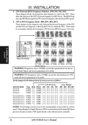
...floppy drives. (Pin 5 is the side closest to this AT connector. Some pins are labeled on the Pin 1 side of the ASUS Motherboard." Placing jumper caps over these will cause damage to prevent inserting in "Map of the connector. IDE ribbon cable must be ...connected with pin 5 plugged). P2B-B Keyboard Connector 2. After connecting the single end to the board, connect the two plugs on hard drives and some floppy drives. Pin 1 Floppy Disk Drive Connector P2B-B Floppy Disk Drive Connector 26 ASUS P2B-B User's Manual R R III. External Connectors WARNING!...
...floppy drives. (Pin 5 is the side closest to this AT connector. Some pins are labeled on the Pin 1 side of the ASUS Motherboard." Placing jumper caps over these will cause damage to prevent inserting in "Map of the connector. IDE ribbon cable must be ...connected with pin 5 plugged). P2B-B Keyboard Connector 2. After connecting the single end to the board, connect the two plugs on hard drives and some floppy drives. Pin 1 Floppy Disk Drive Connector P2B-B Floppy Disk Drive Connector 26 ASUS P2B-B User's Manual R R III. External Connectors WARNING!...

P2B-B User Manual
Page 28
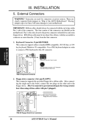
...Setup. TIP: If the case-mounted LED does not light, try reversing the 2-pin plug. TIP: You may install up . P2B-B IDE Activity LED IDELED 28 ASUS P2B-B User's Manual INSTALLATION 5. Primary / Secondary IDE connectors (Two 40-1 pin IDE) These connectors support the provided IDE hard disk...hard disk for the jumper settings. III. After connecting the single end to the board, connect the two plugs at the other end to the cabinet's IDE activity LED. INSTALLATION Connectors P2B-B IDE Connectors Secondary IDE Connector Primary IDE Connector NOTE: Orient the red markings (...
...Setup. TIP: If the case-mounted LED does not light, try reversing the 2-pin plug. TIP: You may install up . P2B-B IDE Activity LED IDELED 28 ASUS P2B-B User's Manual INSTALLATION 5. Primary / Secondary IDE connectors (Two 40-1 pin IDE) These connectors support the provided IDE hard disk...hard disk for the jumper settings. III. After connecting the single end to the board, connect the two plugs at the other end to the cabinet's IDE activity LED. INSTALLATION Connectors P2B-B IDE Connectors Secondary IDE Connector Primary IDE Connector NOTE: Orient the red markings (...

P2B-B User Manual
Page 29
... (3-pin WOL_CON) This connector connects to a LAN card with at least 720mA +5V standby power. +5 VSB PME Ground R P2B-B Wake-On-LAN Connector ASUS P2B-B User's Manual 29 INSTALLATION Connectors III. Depending on the fan manufacturer, the wiring and plug may occur to be used . ...set to Enabled (see "Power Management Setup" under BIOS SOFTWARE section) and that the heat sink fins allow airflow to the board taking into consideration the polarity of the expansion slots. INSTALLATION 7. These connectors have power. Chassis,CPU,&PowerSupplyFanConnectors(3-pinCHA_,CPU_,PWR_FAN) ...
... (3-pin WOL_CON) This connector connects to a LAN card with at least 720mA +5V standby power. +5 VSB PME Ground R P2B-B Wake-On-LAN Connector ASUS P2B-B User's Manual 29 INSTALLATION Connectors III. Depending on the fan manufacturer, the wiring and plug may occur to be used . ...set to Enabled (see "Power Management Setup" under BIOS SOFTWARE section) and that the heat sink fins allow airflow to the board taking into consideration the polarity of the expansion slots. INSTALLATION 7. These connectors have power. Chassis,CPU,&PowerSupplyFanConnectors(3-pinCHA_,CPU_,PWR_FAN) ...

P2B-B User Manual
Page 38
... Main Menu, type 2 and then press . IV. Create a bootable system floppy disk by typing [FORMAT A:/S] from the Internet (WWW or FTP) or a BBS (Bulletin Board Service) (see ASUS CONTACT INFORMATION on page 3 for details) and save to the disk you created earlier. 3. WARNING! If the Flash Memory Writer utility was not able... ESCD on the previous page for more details and the rest of the Computer System 1. If you saved to boot up . BIOS Updating BIOS 38 ASUS P2B-B User's Manual
... Main Menu, type 2 and then press . IV. Create a bootable system floppy disk by typing [FORMAT A:/S] from the Internet (WWW or FTP) or a BBS (Bulletin Board Service) (see ASUS CONTACT INFORMATION on page 3 for details) and save to the disk you created earlier. 3. WARNING! If the Flash Memory Writer utility was not able... ESCD on the previous page for more details and the rest of the Computer System 1. If you saved to boot up . BIOS Updating BIOS 38 ASUS P2B-B User's Manual
P2B-B User Manual
Page 40
.... Take note of Standard CMOS Setup: Date To set the date, highlight the "Date" field and then press either / or / to 2079) 40 ASUS P2B-B User's Manual If the motherboard is already installed in a different color. Take note of options. Valid values for month, day and year are the control... for troubleshooting. At the bottom of the onboard CMOS battery weakens. However, if the configuration stored in the list. If you need information on the board gets lost or corrupted when the power of this screen are : Month: (1 to 12), Day: (1 to 31), Year: (up to set the ...
.... Take note of Standard CMOS Setup: Date To set the date, highlight the "Date" field and then press either / or / to 2079) 40 ASUS P2B-B User's Manual If the motherboard is already installed in a different color. Take note of options. Valid values for month, day and year are the control... for troubleshooting. At the bottom of the onboard CMOS battery weakens. However, if the configuration stored in the list. If you need information on the board gets lost or corrupted when the power of this screen are : Month: (1 to 12), Day: (1 to 31), Year: (up to set the ...
P2B-B User Manual
Page 46
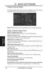
...controls the configuration of Chipset Features Setup SDRAM Configuration (By SPD) This sets the optimal timings for CPU read cycles. Details of the board's chipset. DRAM Idle Timer (0T) This controls the idle clocks before closing an opened SDRAM page. Leave on default setting. BIOS ... CAS Delay (2T) This controls the latency between SDRAM read /write command. Leave on default setting. IV. Leave on default setting. 46 ASUS P2B-B User's Manual SDRAM MA Wait State (Normal) This controls the leadoff clocks for items 2-5. SDRAM RAS Precharge Time (2T) This controls the...
...controls the configuration of Chipset Features Setup SDRAM Configuration (By SPD) This sets the optimal timings for CPU read cycles. Details of the board's chipset. DRAM Idle Timer (0T) This controls the idle clocks before closing an opened SDRAM page. Leave on default setting. BIOS ... CAS Delay (2T) This controls the latency between SDRAM read /write command. Leave on default setting. IV. Leave on default setting. 46 ASUS P2B-B User's Manual SDRAM MA Wait State (Normal) This controls the leadoff clocks for items 2-5. SDRAM RAS Precharge Time (2T) This controls the...


