User Manual
Page 1
Motherboard NCL-DS1 Series NCL-DS1 NCL-D1 NCL-DS1R1 NCL-DS1R2 NCL-D1R1
Motherboard NCL-DS1 Series NCL-DS1 NCL-D1 NCL-DS1R1 NCL-DS1R2 NCL-D1R1
User Manual
Page 3
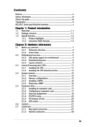
Contents Notices vi Safety information vii About this guide viii Typography ix NCL-DS1 Series specifications summary x Chapter 1: Product introduction 1.1 Welcome 1-1 1.2 Package contents 1-1 1.3 Special features 1-2 1.3.1 Product highlights 1-2 1.3.2 Innovative ASUS features 1-4 Chapter 2: Hardware information 2.1 Before you proceed 1 2.2.1 Placement direction 2 2.2.2 Screw holes 2 2.2 Motherboard overview 2 2.2.3 CEK spring support for motherboard 3 2.2.4 Motherboard layouts 6 2.2.5 Layout contents 9 2.3 Central Processing...
Contents Notices vi Safety information vii About this guide viii Typography ix NCL-DS1 Series specifications summary x Chapter 1: Product introduction 1.1 Welcome 1-1 1.2 Package contents 1-1 1.3 Special features 1-2 1.3.1 Product highlights 1-2 1.3.2 Innovative ASUS features 1-4 Chapter 2: Hardware information 2.1 Before you proceed 1 2.2.1 Placement direction 2 2.2.2 Screw holes 2 2.2 Motherboard overview 2 2.2.3 CEK spring support for motherboard 3 2.2.4 Motherboard layouts 6 2.2.5 Layout contents 9 2.3 Central Processing...

User Manual
Page 10
... : Intel® E7520 Memory Controller Hub (MCH) Southbridge : Intel® ICH5R PCI bridge : Intel® PXH (NCL-D1R1 model has one PCI bridge) (NCL-DS1, NCL-D1, NCL-DS1R1, and NCL-DS1R2 models have two PCI bridges) 800 MHz Dual-channel memory architecture 8 x 184-pin DIMM sockets support registered ECC 333...x PCI-X 133 MHz/64-bit slot (PCI-X 1.0) 1 x PCI 33 MHz/32-bit/5V (PCI 2.3) (NCL-DS1 and NCL-D1 models include all the above slots NCL-DS1R2 includes only two PCI-X 64-bit slots) NCL-DS1R1 and NCL-D1R1 include only one PCI-X 64-bit slot) 1 x SO-DIMM Socket for Adaptec® ASR-2015S...
... : Intel® E7520 Memory Controller Hub (MCH) Southbridge : Intel® ICH5R PCI bridge : Intel® PXH (NCL-D1R1 model has one PCI bridge) (NCL-DS1, NCL-D1, NCL-DS1R1, and NCL-DS1R2 models have two PCI bridges) 800 MHz Dual-channel memory architecture 8 x 184-pin DIMM sockets support registered ECC 333...x PCI-X 133 MHz/64-bit slot (PCI-X 1.0) 1 x PCI 33 MHz/32-bit/5V (PCI 2.3) (NCL-DS1 and NCL-D1 models include all the above slots NCL-DS1R2 includes only two PCI-X 64-bit slots) NCL-DS1R1 and NCL-D1R1 include only one PCI-X 64-bit slot) 1 x SO-DIMM Socket for Adaptec® ASR-2015S...

User Manual
Page 11
... panel Internal connectors Power Requirement Form Factor Support CD contents ASUS Smart Fan ASUS CrashFree BIOS 2 ASUS MyLogo2 AMI BIOS, 8 MB Flash ROM, Green, PnP, DMI2.0a, SMBIOS 2.3, WfM2.0 1 x PS/2 keyboard port (purple) 1 x PS/2 mouse port (green) 2 x USB 2.0/1.1 ports 1 x Parallel port (NCL-DS and NCL-D models only) 1 x Serial port 1 x VGA port 2 x LAN (RJ-45...supply (with 24-pin and 8-pin 12V plugs) ATX 12V 2.0 compliant E-ATX form factor: 12 in x 13 in (30.5 cm x 33 cm) Device drivers ASUS Live Update Utility Anti-virus software *Specifications are subject to change without notice.
... panel Internal connectors Power Requirement Form Factor Support CD contents ASUS Smart Fan ASUS CrashFree BIOS 2 ASUS MyLogo2 AMI BIOS, 8 MB Flash ROM, Green, PnP, DMI2.0a, SMBIOS 2.3, WfM2.0 1 x PS/2 keyboard port (purple) 1 x PS/2 mouse port (green) 2 x USB 2.0/1.1 ports 1 x Parallel port (NCL-DS and NCL-D models only) 1 x Serial port 1 x VGA port 2 x LAN (RJ-45...supply (with 24-pin and 8-pin 12V plugs) ATX 12V 2.0 compliant E-ATX form factor: 12 in x 13 in (30.5 cm x 33 cm) Device drivers ASUS Live Update Utility Anti-virus software *Specifications are subject to change without notice.

User Manual
Page 15
... user guide ASWM 2.0 user guide If any of the above items is damaged or missing, contact your retailer. ASUS NCL-DS1 Series 1-1 Thank you start installing the motherboard, and hardware devices on it another standout in the long line... latest technologies, making it , check the items in your package with the list below. 1.2 Package contents Check your motherboard package for the following items. Motherboard ASUS NCL-DS1 Series motherboard Cables 2 x Serial ATA signal cables (2-in-1) 1 x Serial ATA power cable (dual-plug) 2 x SCSI Ultra320 cables ( f o r S C S I m o d e l s o n l y ) ...
... user guide ASWM 2.0 user guide If any of the above items is damaged or missing, contact your retailer. ASUS NCL-DS1 Series 1-1 Thank you start installing the motherboard, and hardware devices on it another standout in the long line... latest technologies, making it , check the items in your package with the list below. 1.2 Package contents Check your motherboard package for the following items. Motherboard ASUS NCL-DS1 Series motherboard Cables 2 x Serial ATA signal cables (2-in-1) 1 x Serial ATA power cable (dual-plug) 2 x SCSI Ultra320 cables ( f o r S C S I m o d e l s o n l y ) ...

User Manual
Page 17
...) is monitored for two SATA connectors and supports the Intel® Matrix Storage Technology. Built-in the Winbond hardware monitor) to prevent overheating and damage. ASUS NCL-DS1 Series 1-3 Gigabit LAN solution The motherboard comes with dual Gigabit LAN controllers to provide a total solution for details. The onboard Broadcom BCM5721 Gigabit LAN...
...) is monitored for two SATA connectors and supports the Intel® Matrix Storage Technology. Built-in the Winbond hardware monitor) to prevent overheating and damage. ASUS NCL-DS1 Series 1-3 Gigabit LAN solution The motherboard comes with dual Gigabit LAN controllers to provide a total solution for details. The onboard Broadcom BCM5721 Gigabit LAN...
User Manual
Page 20
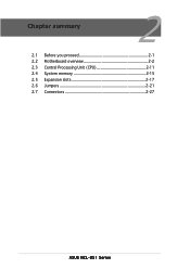
Chapter summary 2 2.1 Before you proceed 2-1 2.2 Motherboard overview 2-2 2.3 Central Processing Unit (CPU 2-11 2.4 System memory 2-15 2.5 Expansion slots 2-17 2.6 Jumpers 2-21 2.7 Connectors 2-27 ASUS NCL-DS1 Series
Chapter summary 2 2.1 Before you proceed 2-1 2.2 Motherboard overview 2-2 2.3 Central Processing Unit (CPU 2-11 2.4 System memory 2-15 2.5 Expansion slots 2-17 2.6 Jumpers 2-21 2.7 Connectors 2-27 ASUS NCL-DS1 Series

User Manual
Page 21
... is ON, in sleep mode, or in the bag that the system is switched off mode. SB_PWR1 ON Standby Power OFF Powered Off NCL-DS1 Series Standby power LED ASUS NCL-DS1 Series 2-1 The green LED lights up to indicate that came with a standby power LED. The illustration below shows the location of...
... is ON, in sleep mode, or in the bag that the system is switched off mode. SB_PWR1 ON Standby Power OFF Powered Off NCL-DS1 Series Standby power LED ASUS NCL-DS1 Series 2-1 The green LED lights up to indicate that came with a standby power LED. The illustration below shows the location of...

User Manual
Page 23
CEK spring Hook To install the CEK spring: 1. ASUS NCL-DS1 Series 2-3 Socket for CPU1 Socket for motherboard For additional protection from motherboard breakage due to match the designated holes around the CPU area. Position ...
CEK spring Hook To install the CEK spring: 1. ASUS NCL-DS1 Series 2-3 Socket for CPU1 Socket for motherboard For additional protection from motherboard breakage due to match the designated holes around the CPU area. Position ...

User Manual
Page 25
Install the motherboard with nine screws. Refer to section "2.2.2 Screw holes" for CPU2 Make sure that the standoffs perfectly match the CEK spring screw holes; otherwise, you can not install the CPU heatsinks properly. 8. ASUS NCL-DS1 Series 2-5 7. Secure the motherboard with the external I/O ports toward the chassis rear panel. The CPU sockets should be right on top of their respective standoffs. Socket for CPU1 Socket for illustration.
Install the motherboard with nine screws. Refer to section "2.2.2 Screw holes" for CPU2 Make sure that the standoffs perfectly match the CEK spring screw holes; otherwise, you can not install the CPU heatsinks properly. 8. ASUS NCL-DS1 Series 2-5 7. Secure the motherboard with the external I/O ports toward the chassis rear panel. The CPU sockets should be right on top of their respective standoffs. Socket for CPU1 Socket for illustration.

User Manual
Page 26
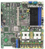
30.5cm (12in) ® NCL-DS1/NCL-D1 2.2.4 Motherboard layouts NCL-DS1 / NCL-D1 models mPGA 604 PARALLEL PORT KBPWR1 PS/2 T: Mouse B: Keyboard REAR_FAN2 USB1 USBPW12 USB2 COM1 33cm (13in) ATXPWR1 PSUSMB1 CPU_FAN1 DDR DIMM_B4 (64/72 bit, ... Intel ICH5R SATA2 SATA1 FRNT_FAN1 FRNT_FAN2 Adaptec AIC-7902W 34 68 SCSIB1 1 35 SCSIA1 • The NCL-DS1 (SCSI model for tower system) includes all the components that appear in the above layout. • The NCL-D1 (non-SCSI model for distinction. 2-6 Chapter 2: Hardware information These items are grayed out in the...
30.5cm (12in) ® NCL-DS1/NCL-D1 2.2.4 Motherboard layouts NCL-DS1 / NCL-D1 models mPGA 604 PARALLEL PORT KBPWR1 PS/2 T: Mouse B: Keyboard REAR_FAN2 USB1 USBPW12 USB2 COM1 33cm (13in) ATXPWR1 PSUSMB1 CPU_FAN1 DDR DIMM_B4 (64/72 bit, ... Intel ICH5R SATA2 SATA1 FRNT_FAN1 FRNT_FAN2 Adaptec AIC-7902W 34 68 SCSIB1 1 35 SCSIA1 • The NCL-DS1 (SCSI model for tower system) includes all the components that appear in the above layout. • The NCL-D1 (non-SCSI model for distinction. 2-6 Chapter 2: Hardware information These items are grayed out in the...

User Manual
Page 27
30.5cm (12in) ® NCL-DS1R1/NCL-DS1R2 NCL-DS1R1 / NCL-DS1R2 models mPGA 604 COM1 KBPWR1 PS/2 T: Mouse B: Keyboard REAR_FAN2 USB1 USBPW12 USB2 33cm (13in) ATXPWR1 PSUSMB1 CPU_FAN1 DDR DIMM_B4 (64/72 bit, 184-pin ... 3V Lithium Cell CMOS Power BUZZ1 CLRTC1 AUX_PANEL1 USB34 USBPW34 Intel PXH HDLED1 SCSI_EN1 PANEL1 Adaptec AIC-7902W 34 68 SCSIB1 1 35 SCSIA1 • The NCL-DS1R1 (SCSI model for 1U rack system) includes only one PCI-X 64-bit slot. • The...
30.5cm (12in) ® NCL-DS1R1/NCL-DS1R2 NCL-DS1R1 / NCL-DS1R2 models mPGA 604 COM1 KBPWR1 PS/2 T: Mouse B: Keyboard REAR_FAN2 USB1 USBPW12 USB2 33cm (13in) ATXPWR1 PSUSMB1 CPU_FAN1 DDR DIMM_B4 (64/72 bit, 184-pin ... 3V Lithium Cell CMOS Power BUZZ1 CLRTC1 AUX_PANEL1 USB34 USBPW34 Intel PXH HDLED1 SCSI_EN1 PANEL1 Adaptec AIC-7902W 34 68 SCSIB1 1 35 SCSIA1 • The NCL-DS1R1 (SCSI model for 1U rack system) includes only one PCI-X 64-bit slot. • The...

User Manual
Page 28
30.5cm (12in) ® NCL-D1R1 NCL-D1R1 model mPGA 604 COM1 KBPWR1 PS/2 T: Mouse B: Keyboard REAR_FAN2 USB1 USBPW12 USB2 33cm (13in) ATXPWR1 PSUSMB1 CPU_FAN1 DDR DIMM_B4 (64/72 bit, 184-pin ... VGA Controller SB_PWR1 COM2 BPSMB1 FLOPPY1 BMCCONN1 CR2032 3V Lithium Cell CMOS Power BUZZ1 CLRTC1 AUX_PANEL1 USB34 HDLED1 PANEL1 USBPW34 SATA2 SATA1 FRNT_FAN1 FRNT_FAN2 The NCL-D1R1 (non-SCSI model for 1U rack system) includes only one PCI-X 64-bit slot. 2-8 Chapter 2: Hardware information
30.5cm (12in) ® NCL-D1R1 NCL-D1R1 model mPGA 604 COM1 KBPWR1 PS/2 T: Mouse B: Keyboard REAR_FAN2 USB1 USBPW12 USB2 33cm (13in) ATXPWR1 PSUSMB1 CPU_FAN1 DDR DIMM_B4 (64/72 bit, 184-pin ... VGA Controller SB_PWR1 COM2 BPSMB1 FLOPPY1 BMCCONN1 CR2032 3V Lithium Cell CMOS Power BUZZ1 CLRTC1 AUX_PANEL1 USB34 HDLED1 PANEL1 USBPW34 SATA2 SATA1 FRNT_FAN1 FRNT_FAN2 The NCL-D1R1 (non-SCSI model for 1U rack system) includes only one PCI-X 64-bit slot. 2-8 Chapter 2: Hardware information

User Manual
Page 29
... (purple) Page 2-11 2-15 2-20 2-20 Page 2-21 2-22 2-22 2-23 2-23 2-24 2-24 2-25 2-25 2-26 Page 2-27 2-27 2-27 2-27 2-27 2-27 2-27 ASUS NCL-DS1 Series 2-9 Keyboard power (3-pin KBPWR1) 5. CPU sockets 2. Force BIOS recovery setting (3-pin RECOVERY1) Rear panel connectors 1. LAN (RJ-45) ports 4. Clear RTC RAM (CLRTC1) 2.
... (purple) Page 2-11 2-15 2-20 2-20 Page 2-21 2-22 2-22 2-23 2-23 2-24 2-24 2-25 2-25 2-26 Page 2-27 2-27 2-27 2-27 2-27 2-27 2-27 ASUS NCL-DS1 Series 2-9 Keyboard power (3-pin KBPWR1) 5. CPU sockets 2. Force BIOS recovery setting (3-pin RECOVERY1) Rear panel connectors 1. LAN (RJ-45) ports 4. Clear RTC RAM (CLRTC1) 2.
User Manual
Page 31
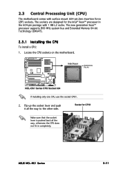
...-pin package with surface mount 604-pin Zero Insertion Force (ZIF) sockets. Intel Xeon Gold Arrow Pin A1 NCL-DS1 Series CPU Socket 604 If installing only one CPU, use the socket CPU1. 2. ASUS NCL-DS1 Series 2-11 The new generation Xeon™ processor supports 800 MHz system bus and Extended Memory 64...
...-pin package with surface mount 604-pin Zero Insertion Force (ZIF) sockets. Intel Xeon Gold Arrow Pin A1 NCL-DS1 Series CPU Socket 604 If installing only one CPU, use the socket CPU1. 2. ASUS NCL-DS1 Series 2-11 The new generation Xeon™ processor supports 800 MHz system bus and Extended Memory 64...

User Manual
Page 33
... the installed CPU, making sure that you have applied the thermal grease to the installation manual that came with the nuts on the support plate. ASUS NCL-DS1 Series 2-13 When you buy a boxed Intel CPU, the package includes the heatsink, fan, retention brackets, screws, thermal grease, installation manual, and other items...
... the installed CPU, making sure that you have applied the thermal grease to the installation manual that came with the nuts on the support plate. ASUS NCL-DS1 Series 2-13 When you buy a boxed Intel CPU, the package includes the heatsink, fan, retention brackets, screws, thermal grease, installation manual, and other items...

User Manual
Page 35
ASUS NCL-DS1 Series 2-15 Refer to the DDR Qualified Vendors List at the ASUS web site. • Due to chipset resource allocation, the system may detect less than 16 GB system memory when you installed eight 2 GB DDR2 memory ...modules. • This motherboard does not support memory modules made up of the DDR DIMM sockets: 80 Pins 104 Pins NCL-DS1 Series...
ASUS NCL-DS1 Series 2-15 Refer to the DDR Qualified Vendors List at the ASUS web site. • Due to chipset resource allocation, the system may detect less than 16 GB system memory when you installed eight 2 GB DDR2 memory ...modules. • This motherboard does not support memory modules made up of the DDR DIMM sockets: 80 Pins 104 Pins NCL-DS1 Series...

User Manual
Page 37
... the card is already installed in a chassis). 3. Assign an IRQ to install expansion cards. Refer to the chassis with it by adjusting the software settings. 1. ASUS NCL-DS1 Series 2-17 When using PCI cards on shared slots, ensure that the drivers support "Share IRQ" or that came with the screw you removed...
... the card is already installed in a chassis). 3. Assign an IRQ to install expansion cards. Refer to the chassis with it by adjusting the software settings. 1. ASUS NCL-DS1 Series 2-17 When using PCI cards on shared slots, ensure that the drivers support "Share IRQ" or that came with the screw you removed...
User Manual
Page 41
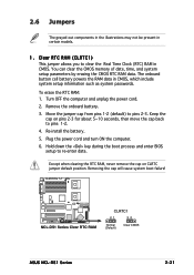
... onboard button cell battery powers the RAM data in CMOS, which include system setup information such as system passwords. NCL-DS1 Series Clear RTC RAM CLRTC1 21 32 Normal (Default) Clear CMOS ASUS NCL-DS1 Series 2-21 Re-install the battery. 5. You can clear the CMOS memory of date, time, and system setup...
... onboard button cell battery powers the RAM data in CMOS, which include system setup information such as system passwords. NCL-DS1 Series Clear RTC RAM CLRTC1 21 32 Normal (Default) Clear CMOS ASUS NCL-DS1 Series 2-21 Re-install the battery. 5. You can clear the CMOS memory of date, time, and system setup...

User Manual
Page 42
... exceed the power supply capability (+5VSB) whether under normal condition or in reduced power mode). Set to +5VSB to the CPU fan connectors (CPU_FAN1, CPU_FAN2). NCL-DS1 Series FM_CPU setting FM_CPU1 2 1 DC mode (Default) 3 2 PWM FM_CPU2 2 1 DC mode (Default) 3 2 PWM 3 . USBPW12 12 23 +5V (Default) +...5VSB USBPW34 1 2 +5V NCL-DS1 Series USB device wake up (Default) 2 3 +5VSB 2-22 • The USB device wake-up from S1 sleep mode (CPU stopped, DRAM refreshed, system running ...
... exceed the power supply capability (+5VSB) whether under normal condition or in reduced power mode). Set to +5VSB to the CPU fan connectors (CPU_FAN1, CPU_FAN2). NCL-DS1 Series FM_CPU setting FM_CPU1 2 1 DC mode (Default) 3 2 PWM FM_CPU2 2 1 DC mode (Default) 3 2 PWM 3 . USBPW12 12 23 +5V (Default) +...5VSB USBPW34 1 2 +5V NCL-DS1 Series USB device wake up (Default) 2 3 +5VSB 2-22 • The USB device wake-up from S1 sleep mode (CPU stopped, DRAM refreshed, system running ...