
User Guide
Page 15
... the items in your package with the list below. 1.2 Package contents Check your retailer. 1.1 Welcome! Before you for buying an ASUS® NCL-DS Series motherboard! * This user guide includes information for NCL-DS model only) 80-conductor IDE cable 3-in the long line of the above items is damaged or missing, contact your motherboard...
... the items in your package with the list below. 1.2 Package contents Check your retailer. 1.1 Welcome! Before you for buying an ASUS® NCL-DS Series motherboard! * This user guide includes information for NCL-DS model only) 80-conductor IDE cable 3-in the long line of the above items is damaged or missing, contact your motherboard...

User Guide
Page 17
... the 12 Mbps bandwidth on USB 2.0. USB 2.0 is backward compatible with lower pin count, reduced voltage requirement, and up to 150 MB/s data transfer rate. ASUS NCL-DS Series 1-3 Serial ATA technology The motherboard supports the Serial ATA technology through the Serial ATA interfaces controlled by the ASIC (integrated in SATA RAID solution...
... the 12 Mbps bandwidth on USB 2.0. USB 2.0 is backward compatible with lower pin count, reduced voltage requirement, and up to 150 MB/s data transfer rate. ASUS NCL-DS Series 1-3 Serial ATA technology The motherboard supports the Serial ATA technology through the Serial ATA interfaces controlled by the ASIC (integrated in SATA RAID solution...

User Guide
Page 20
Chapter summary 2 2.1 Before you proceed 2-1 2.2 Motherboard overview 2-2 2.3 Central Processing Unit (CPU 2-11 2.4 System memory 2-15 2.5 Expansion slots 2-18 2.6 Jumpers 2-21 2.7 Connectors 2-26 ASUS NCL-DS Series
Chapter summary 2 2.1 Before you proceed 2-1 2.2 Motherboard overview 2-2 2.3 Central Processing Unit (CPU 2-11 2.4 System memory 2-15 2.5 Expansion slots 2-18 2.6 Jumpers 2-21 2.7 Connectors 2-26 ASUS NCL-DS Series
User Guide
Page 21
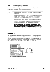
... the edges to the motherboard, peripherals, and/or components. 2.1 Before you proceed Take note of the onboard LED. SB_PWR1 ON Standby Power OFF Powered Off NCL-DS Series Standby power LED ASUS NCL-DS Series 2-1
... the edges to the motherboard, peripherals, and/or components. 2.1 Before you proceed Take note of the onboard LED. SB_PWR1 ON Standby Power OFF Powered Off NCL-DS Series Standby power LED ASUS NCL-DS Series 2-1
User Guide
Page 23
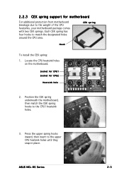
..., then match the CEK spring hooks to the upper CPU heatsink holes until they snap in place. CEK spring Hook To install the CEK spring: 1. ASUS NCL-DS Series 2-3 Socket for CPU1 Socket for motherboard For additional protection from motherboard breakage due to match the designated holes around the CPU area. Press the...
..., then match the CEK spring hooks to the upper CPU heatsink holes until they snap in place. CEK spring Hook To install the CEK spring: 1. ASUS NCL-DS Series 2-3 Socket for CPU1 Socket for motherboard For additional protection from motherboard breakage due to match the designated holes around the CPU area. Press the...
User Guide
Page 25
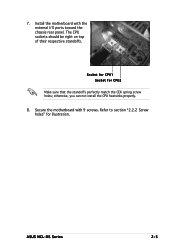
The CPU sockets should be right on top of their respective standoffs. Install the motherboard with 9 screws. otherwise, you can not install the CPU heatsinks properly. 8. Secure the motherboard with the external I/O ports toward the chassis rear panel. Refer to section "2.2.2 Screw holes" for CPU2 Make sure that the standoffs perfectly match the CEK spring screw holes; ASUS NCL-DS Series 2-5 Socket for CPU1 Socket for illustration. 7.
The CPU sockets should be right on top of their respective standoffs. Install the motherboard with 9 screws. otherwise, you can not install the CPU heatsinks properly. 8. Secure the motherboard with the external I/O ports toward the chassis rear panel. Refer to section "2.2.2 Screw holes" for CPU2 Make sure that the standoffs perfectly match the CEK spring screw holes; ASUS NCL-DS Series 2-5 Socket for CPU1 Socket for illustration. 7.

User Guide
Page 27
® 30.5cm (12in) NCL-D NCL-D model 33cm (13in) mPGA 604 PS/2 T: Mouse B: Keyboard ATXPWR1 REAR_FAN2 PSUSMB1 CPU_FAN1 USB1 KBPWR1 USB2 DDR DIMM_B4 (64/72 bit, 240-pin module) DDR DIMM_A4 (...-bit, 33MHz 5V) BPSMB1 FLOPPY1 CR2032 3V Lithium Cell CMOS Power BUZZ1 CLRTC1 AUX_PANEL1 USB34 HDLED1 SB_PWR1 COM2 BMCCONN1 PANEL1 SATA2 SATA1 FRNT_FAN1 FRNT_FAN2 The NCL-D model supports RAID feature through the Intel® ICH5R southbridge and two SATA connectors. ASUS NCL-DS Series 2-7
® 30.5cm (12in) NCL-D NCL-D model 33cm (13in) mPGA 604 PS/2 T: Mouse B: Keyboard ATXPWR1 REAR_FAN2 PSUSMB1 CPU_FAN1 USB1 KBPWR1 USB2 DDR DIMM_B4 (64/72 bit, 240-pin module) DDR DIMM_A4 (...-bit, 33MHz 5V) BPSMB1 FLOPPY1 CR2032 3V Lithium Cell CMOS Power BUZZ1 CLRTC1 AUX_PANEL1 USB34 HDLED1 SB_PWR1 COM2 BMCCONN1 PANEL1 SATA2 SATA1 FRNT_FAN1 FRNT_FAN2 The NCL-D model supports RAID feature through the Intel® ICH5R southbridge and two SATA connectors. ASUS NCL-DS Series 2-7

User Guide
Page 29
.../2 keyboard port (purple) Page 2-9 2-13 2-18 2-18 Page 2-21 2-22 2-22 2-23 2-23 2-24 2-24 2-25 2-25 Page 2-26 2-26 2-26 2-26 2-26 2-26 2-26 ASUS NCL-DS Series 2-9 Zero-Channel RAID socket Jumpers 1. USB device wake-up (3-pin USBPW12, USBPW34) 4. Gigabit LAN controller setting (3-pin LAN1_EN1) 7. Parallel port 3. USB 2.0 ports 1 and 2 7. SCSI...
.../2 keyboard port (purple) Page 2-9 2-13 2-18 2-18 Page 2-21 2-22 2-22 2-23 2-23 2-24 2-24 2-25 2-25 Page 2-26 2-26 2-26 2-26 2-26 2-26 2-26 ASUS NCL-DS Series 2-9 Zero-Channel RAID socket Jumpers 1. USB device wake-up (3-pin USBPW12, USBPW34) 4. Gigabit LAN controller setting (3-pin LAN1_EN1) 7. Parallel port 3. USB 2.0 ports 1 and 2 7. SCSI...

User Guide
Page 31
... designed for CPU1 Make sure that the socket lever is pushed back all the way to the other side. Intel Xeon Gold Arrow Pin A1 NCL-DS Series CPU Socket 604 If installing only one CPU, use the socket CPU1. 2. The new generation Xeon™ processor supports 800 MHz system bus and... mount 604-pin Zero Insertion Force (ZIF) sockets. Socket for the Intel® Xeon™ processor in completely. Locate the CPU sockets on the motherboard. ASUS NCL-DS Series 2-11
... designed for CPU1 Make sure that the socket lever is pushed back all the way to the other side. Intel Xeon Gold Arrow Pin A1 NCL-DS Series CPU Socket 604 If installing only one CPU, use the socket CPU1. 2. The new generation Xeon™ processor supports 800 MHz system bus and... mount 604-pin Zero Insertion Force (ZIF) sockets. Socket for the Intel® Xeon™ processor in completely. Locate the CPU sockets on the motherboard. ASUS NCL-DS Series 2-11

User Guide
Page 33
...™ processors require an Intel certified heatsink and fan assembly to page 2-19 for information on these jumpers. To install the CPU heatsink and fan: 1. ASUS NCL-DS Series 2-13 Place the heatsink on top of your CPU fan cables. When you have applied the thermal grease to the top of the CPU...
...™ processors require an Intel certified heatsink and fan assembly to page 2-19 for information on these jumpers. To install the CPU heatsink and fan: 1. ASUS NCL-DS Series 2-13 Place the heatsink on top of your CPU fan cables. When you have applied the thermal grease to the top of the CPU...
User Guide
Page 35
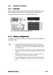
The figure illustrates the location of the DDR2 DIMM sockets: 128 Pins NCL-DS Series 240-pin DDR2 DIMM sockets 112 Pins DIMM_B4 DIMM_A4 DIMM_B3 DIMM_A3 DIMM_B2 DIMM_A2 DIMM_B1 DIMM_A1 2.4.2 Memory configurations You may install 256 MB, 512 MB ... into any other socket would not work. Installing into the blue socket labeled DIMM_B4. 2.4 System memory 2.4.1 Overview The motherboard comes with the same CAS latency. ASUS NCL-DS Series 2-15 Refer to the DDR2 Qualified Vendors List at the ASUS web site. • Due to support 240-pin DDR2 modules.
The figure illustrates the location of the DDR2 DIMM sockets: 128 Pins NCL-DS Series 240-pin DDR2 DIMM sockets 112 Pins DIMM_B4 DIMM_A4 DIMM_B3 DIMM_A3 DIMM_B2 DIMM_A2 DIMM_B1 DIMM_A1 2.4.2 Memory configurations You may install 256 MB, 512 MB ... into any other socket would not work. Installing into the blue socket labeled DIMM_B4. 2.4 System memory 2.4.1 Overview The motherboard comes with the same CAS latency. ASUS NCL-DS Series 2-15 Refer to the DDR2 Qualified Vendors List at the ASUS web site. • Due to support 240-pin DDR2 modules.
User Guide
Page 37
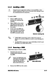
.... To install a DIMM: 1. Simultaneously press the retaining clips outward to both the motherboard and the components. Remove the DIMM from the socket. 2 1 DDR2 DIMM notch ASUS NCL-DS Series 2-17 2.4.3 Installing a DIMM Unplug the power supply before adding or removing DIMMs or other system components. Firmly insert the DIMM into a socket to avoid...
.... To install a DIMM: 1. Simultaneously press the retaining clips outward to both the motherboard and the components. Remove the DIMM from the socket. 2 1 DDR2 DIMM notch ASUS NCL-DS Series 2-17 2.4.3 Installing a DIMM Unplug the power supply before adding or removing DIMMs or other system components. Firmly insert the DIMM into a socket to avoid...

User Guide
Page 39
ASUS NCL-DS Series 2-19 2.5.3 Interrupt assignments Standard interrupt assignments IRQ Priority 0 1 1 2 2 - 3 11 4 12 5 13 6 14 7 15 8 3 9 4 10 5 11 6 12 7 13 8 14 9 15 10 Standard Function System Timer ...
ASUS NCL-DS Series 2-19 2.5.3 Interrupt assignments Standard interrupt assignments IRQ Priority 0 1 1 2 2 - 3 11 4 12 5 13 6 14 7 15 8 3 9 4 10 5 11 6 12 7 13 8 14 9 15 10 Standard Function System Timer ...
User Guide
Page 41
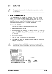
... pins 1-2 (default) to re-enter data. Hold down the key during the boot process and enter BIOS setup to pins 2-3. NCL-DS Series Clear RTC RAM CLRTC1 12 23 Normal (Default) Clear CMOS ASUS NCL-DS Series 2-21 Re-install the battery. 5. Clear RTC RAM (CLRTC1) This jumper allows you to pins 1-2. 4. Keep the cap...
... pins 1-2 (default) to re-enter data. Hold down the key during the boot process and enter BIOS setup to pins 2-3. NCL-DS Series Clear RTC RAM CLRTC1 12 23 Normal (Default) Clear CMOS ASUS NCL-DS Series 2-21 Re-install the battery. 5. Clear RTC RAM (CLRTC1) This jumper allows you to pins 1-2. 4. Keep the cap...

User Guide
Page 43
...ATX power supply that can supply at least 1A on the keyboard (the default is the Space Bar). KBPWR1 12 23 +5V (Default) +5VSB NCL-DS Series Keyboard power setting 5 . Set to pins 1-2 to wake up feature. Keyboard power (3-pin KBPWR1) This jumper allows you to enable or ... VGA controller setting (3-pin VGA_EN1) These jumpers allow you to enable or disable the onboard ATI® RAGE-XL PCI VGA controller. 4. NCL-DS Series VGA setting VGA_EN1 1 2 Enable (Default) 2 3 Disable ASUS NCL-DS Series 2-23 Set this jumper to pins 2-3 (+5VSB) to activate the VGA feature.
...ATX power supply that can supply at least 1A on the keyboard (the default is the Space Bar). KBPWR1 12 23 +5V (Default) +5VSB NCL-DS Series Keyboard power setting 5 . Set to pins 1-2 to wake up feature. Keyboard power (3-pin KBPWR1) This jumper allows you to enable or ... VGA controller setting (3-pin VGA_EN1) These jumpers allow you to enable or disable the onboard ATI® RAGE-XL PCI VGA controller. 4. NCL-DS Series VGA setting VGA_EN1 1 2 Enable (Default) 2 3 Disable ASUS NCL-DS Series 2-23 Set this jumper to pins 2-3 (+5VSB) to activate the VGA feature.

User Guide
Page 45
... or disable the onboard Adaptec® AIC-7902 SCSI U320 controller. RECOVERY1 12 23 Normal BIOS Recovery (Default) NCL-DS Series BIOS recovery setting ASUS NCL-DS Series 2-25 Set the jumper back to activate the SCSI feature, and support RAID configurations. Set to pins 1-2... to pins 1-2. 6. Shut down the system. 5. NCL-DS Series SCSI setting SCSI_EN1 12 23 Enable (Default) Disable 9 . Turn on the system to pins 2-3. ...
... or disable the onboard Adaptec® AIC-7902 SCSI U320 controller. RECOVERY1 12 23 Normal BIOS Recovery (Default) NCL-DS Series BIOS recovery setting ASUS NCL-DS Series 2-25 Set the jumper back to activate the SCSI feature, and support RAID configurations. Set to pins 1-2... to pins 1-2. 6. Shut down the system. 5. NCL-DS Series SCSI setting SCSI_EN1 12 23 Enable (Default) Disable 9 . Turn on the system to pins 2-3. ...

User Guide
Page 47
Pin 5 on the connector is removed to PIN 1. NCL-DS Series IDE connectors ASUS NCL-DS Series SEC_IDE PIN 1 PRI_IDE PIN 1 NOTE: Orient the red markings (usually zigzag) on the floppy ribbon cable to match the covered hole on the Ultra .../66 signal cable. Primary IDE connectors (40-1 pin PRI_IDE, SEC_IDE) These connectors are for an Ultra DMA 100/66 IDE master device (hard disk drive). NCL-DS Series Floppy disk drive connector 2 . The Ultra DMA 100/66 signal cable has three connectors: a blue connector for the primary IDE connector on the IDE...
Pin 5 on the connector is removed to PIN 1. NCL-DS Series IDE connectors ASUS NCL-DS Series SEC_IDE PIN 1 PRI_IDE PIN 1 NOTE: Orient the red markings (usually zigzag) on the floppy ribbon cable to match the covered hole on the Ultra .../66 signal cable. Primary IDE connectors (40-1 pin PRI_IDE, SEC_IDE) These connectors are for an Ultra DMA 100/66 IDE master device (hard disk drive). NCL-DS Series Floppy disk drive connector 2 . The Ultra DMA 100/66 signal cable has three connectors: a blue connector for the primary IDE connector on the IDE...

User Guide
Page 49
With Ultra320 devices, the SCSI bus platform performs at full Ultra320 speeds (up to 15 devices) NCL-DS Series SCSI connection example 68-pin Female Terminator ASUS NCL-DS Series 2-29 Ultra320, Ultra160, Ultra2, Ultra-Wide). Each channel can support a maximum of 15 devices as shown. one for ...68-Pin Ultra320/ 1 35 Ultra2-Wide SCSI Connector SCSIA1 68-Pin Ultra320/ Ultra2-Wide SCSI Connector 34 1 34 68 68 35 NCL-DS Series Onboard SCSI connectors SCSI Connection Notes This motherboard has two 68-Pin Ultra320 SCSI connectors; Mixing SCSI devices on the same channel decreases...
With Ultra320 devices, the SCSI bus platform performs at full Ultra320 speeds (up to 15 devices) NCL-DS Series SCSI connection example 68-pin Female Terminator ASUS NCL-DS Series 2-29 Ultra320, Ultra160, Ultra2, Ultra-Wide). Each channel can support a maximum of 15 devices as shown. one for ...68-Pin Ultra320/ 1 35 Ultra2-Wide SCSI Connector SCSIA1 68-Pin Ultra320/ Ultra2-Wide SCSI Connector 34 1 34 68 68 35 NCL-DS Series Onboard SCSI connectors SCSI Connection Notes This motherboard has two 68-Pin Ultra320 SCSI connectors; Mixing SCSI devices on the same channel decreases...

User Guide
Page 51
... GND FAN Power FAN Speed PWM Control PWM Control FAN Speed FAN Power GND CPU_FAN1 REAR_FAN2 CPU_FAN1 CPU_FAN2 REAR_FAN1 CPU_FAN2 FRNT_FAN1 FRNT_FAN2 NCL-DS Series Fan connectors REAR_FAN1 GND +12V Rotation FRNT_FAN1 GND +12V Rotation REAR_FAN2 Rotation +12V GND FRNT_FAN2 GND +12V Rotation 8 ... fan cables to the fan connectors on the fan connectors! I2C_7_CLK# I2C_7_DATA# NC GND +3.3V Remote Sense PSUSMB1 NCL-DS Series Power supply SMBus connector ASUS NCL-DS Series 2-31 CPU and system fan connectors (3-pin CPU_FAN1/2, REAR_FAN1/2, FRNT_FAN1/2) The fan connectors support cooling fans of...
... GND FAN Power FAN Speed PWM Control PWM Control FAN Speed FAN Power GND CPU_FAN1 REAR_FAN2 CPU_FAN1 CPU_FAN2 REAR_FAN1 CPU_FAN2 FRNT_FAN1 FRNT_FAN2 NCL-DS Series Fan connectors REAR_FAN1 GND +12V Rotation FRNT_FAN1 GND +12V Rotation REAR_FAN2 Rotation +12V GND FRNT_FAN2 GND +12V Rotation 8 ... fan cables to the fan connectors on the fan connectors! I2C_7_CLK# I2C_7_DATA# NC GND +3.3V Remote Sense PSUSMB1 NCL-DS Series Power supply SMBus connector ASUS NCL-DS Series 2-31 CPU and system fan connectors (3-pin CPU_FAN1/2, REAR_FAN1/2, FRNT_FAN1/2) The fan connectors support cooling fans of...

User Guide
Page 53
... BMC connector (16-pin BMCCONN1) This connector is recommended for the ASUS server management card, if available. +5VSB +5VSB BMC SMBCLK 12CCLK1 PSON# BMC_RST# PWROK PSONEN# BMCCONN1 NCL-DS Series BMC connector ASUS NCL-DS Series +5VSB +5VSB BMC SMBDATA 12CDATA1 FP_PWRBTN# BMC_PRESENT# BMC_SMI# GND... +12 Volts +3 Volts 12V 12V 12V 12V +3 Volts -12 Volts Ground PSON# Ground Ground Ground -5 Volts +5 Volts +5 Volts +5 Volts Ground NCL-DS Series ATX Power connectors For Power Supply with a higher power rating if you intend to fit these connectors in only one orientation. p i n A ...
... BMC connector (16-pin BMCCONN1) This connector is recommended for the ASUS server management card, if available. +5VSB +5VSB BMC SMBCLK 12CCLK1 PSON# BMC_RST# PWROK PSONEN# BMCCONN1 NCL-DS Series BMC connector ASUS NCL-DS Series +5VSB +5VSB BMC SMBDATA 12CDATA1 FP_PWRBTN# BMC_PRESENT# BMC_SMI# GND... +12 Volts +3 Volts 12V 12V 12V 12V +3 Volts -12 Volts Ground PSON# Ground Ground Ground -5 Volts +5 Volts +5 Volts +5 Volts Ground NCL-DS Series ATX Power connectors For Power Supply with a higher power rating if you intend to fit these connectors in only one orientation. p i n A ...


