User Guide
Page 3
... guide...iv Package contents...vi N3150I-C / N3050I-C specifications summary vi Chapter 1: Product introduction 1.1 Before you proceed 1-1 1.2 Motherboard overview 1-2 1.3 Central Processing Unit (CPU 1-4 1.4 System memory 1-4 1.5 Expansion slots 1-7 1.6 Headers...1-8 1.7 Connectors 1-10 1.8 Software support 1-18 1.9 Windows® 7 and USB 3.0 driver installation 1-19 Chapter 2: BIOS information 2.1 Managing and updating your BIOS 2-1 2.2 BIOS setup program 2-6 2.3 My Favorites 2-10 2.4 Main...
... guide...iv Package contents...vi N3150I-C / N3050I-C specifications summary vi Chapter 1: Product introduction 1.1 Before you proceed 1-1 1.2 Motherboard overview 1-2 1.3 Central Processing Unit (CPU 1-4 1.4 System memory 1-4 1.5 Expansion slots 1-7 1.6 Headers...1-8 1.7 Connectors 1-10 1.8 Software support 1-18 1.9 Windows® 7 and USB 3.0 driver installation 1-19 Chapter 2: BIOS information 2.1 Managing and updating your BIOS 2-1 2.2 BIOS setup program 2-6 2.3 My Favorites 2-10 2.4 Main...
User Guide
Page 4
... • Ensure that the power cables for the devices are unplugged before the signal cables are not sure about the voltage of the BIOS parameters are unplugged. • Seek professional assistance before using , contact your retailer. Safety information Electrical safety • To prevent electrical ...8226; When adding or removing devices to or from the system, ensure that your power supply is set to change system settings through the BIOS Setup menus. iv If you add a device. • Before connecting or removing signal cables from the motherboard, ensure that came with ...
... • Ensure that the power cables for the devices are unplugged before the signal cables are not sure about the voltage of the BIOS parameters are unplugged. • Seek professional assistance before using , contact your retailer. Safety information Electrical safety • To prevent electrical ...8226; When adding or removing devices to or from the system, ensure that your power supply is set to change system settings through the BIOS Setup menus. iv If you add a device. • Before connecting or removing signal cables from the motherboard, ensure that came with ...

User Guide
Page 7
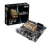
... information Wfm 2.0, DMI 2.0, WOL by PME, PXE Windows® 8.1 64-bit, Window® 7 64-bit (continued on the next page) vii ASUS Fan Xpert - ASUS USB 3.0 Boost ASUS Quiet Thermal Solution - ASUS EZ-Flash 2 - N3150I-C / N3050I-C specifications summary ASUS Unique Features Back Panel I/O Ports Internal I/O Connectors BIOS features Manageability Operating System Support ASUS Exclusive Features - ASUS Anti-surge Protection -
... information Wfm 2.0, DMI 2.0, WOL by PME, PXE Windows® 8.1 64-bit, Window® 7 64-bit (continued on the next page) vii ASUS Fan Xpert - ASUS USB 3.0 Boost ASUS Quiet Thermal Solution - ASUS EZ-Flash 2 - N3150I-C / N3050I-C specifications summary ASUS Unique Features Back Panel I/O Ports Internal I/O Connectors BIOS features Manageability Operating System Support ASUS Exclusive Features - ASUS Anti-surge Protection -
User Guide
Page 11
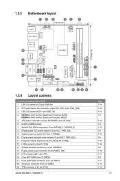
LPT connector (26-1 pin LPT) 16. Serial port connector (10-1 pin COM2) 19. TPM connector (14-1 pin TPM) ASUS N3150I-C / N3050I-C Mini PCIe SATA6G_1 SATA6G_2 N3150I-C N3050I-C DDR3_DIMM_A1 (64bit, 240-pin module) DDR3_DIMM_B1 (64bit, 240-pin module) EATX_PWR 17.0cm(6.7in) 5 7 Page 1-14 1-12 1-14 1-4 1-13 1-4 1-15 1-8 ...1442K Intel® SOC HDMI BATTERY 18 17 16 COM1 VGA AAFP BZ1 COM2 TPM AUDIO1 RTL 8111H CLCMOS ALC 887 64Mb BIOS Super I/O LPT PANEL_SW CHASSIS PCIEX4 LVDS LCD_BLKT_PANEL VCC_PWR_SEL BLKT_PWR_SEL F_PANEL 15 14 13 12 11 10 9 8 1.2.4 Layout contents ...
LPT connector (26-1 pin LPT) 16. Serial port connector (10-1 pin COM2) 19. TPM connector (14-1 pin TPM) ASUS N3150I-C / N3050I-C Mini PCIe SATA6G_1 SATA6G_2 N3150I-C N3050I-C DDR3_DIMM_A1 (64bit, 240-pin module) DDR3_DIMM_B1 (64bit, 240-pin module) EATX_PWR 17.0cm(6.7in) 5 7 Page 1-14 1-12 1-14 1-4 1-13 1-4 1-15 1-8 ...1442K Intel® SOC HDMI BATTERY 18 17 16 COM1 VGA AAFP BZ1 COM2 TPM AUDIO1 RTL 8111H CLCMOS ALC 887 64Mb BIOS Super I/O LPT PANEL_SW CHASSIS PCIEX4 LVDS LCD_BLKT_PANEL VCC_PWR_SEL BLKT_PWR_SEL F_PANEL 15 14 13 12 11 10 9 8 1.2.4 Layout contents ...
User Guide
Page 15
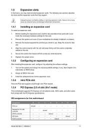
...an expansion card: 1. Before installing the expansion card, read the documentation that comply with the screw you removed earlier. 6. Turn on BIOS setup. 2. IRQ assignments for later use . ASUS N3150I-C / N3050I-C 1-7 Align the card connector with it by adjusting the software settings. 1. Failure to do so may need to the card. 3....card After installing the expansion card, configure it and make the necessary hardware settings for information on the system and change the necessary BIOS settings, if any. See Chapter 2 for the card. 2. shared - - - - - - - - - -
...an expansion card: 1. Before installing the expansion card, read the documentation that comply with the screw you removed earlier. 6. Turn on BIOS setup. 2. IRQ assignments for later use . ASUS N3150I-C / N3050I-C 1-7 Align the card connector with it by adjusting the software settings. 1. Failure to do so may need to the card. 3....card After installing the expansion card, configure it and make the necessary hardware settings for information on the system and change the necessary BIOS settings, if any. See Chapter 2 for the card. 2. shared - - - - - - - - - -

User Guide
Page 16
Hold down and reboot the system, then the BIOS automatically resets parameter settings to short the two pins. 3. CLCMOS N3150I-C N3050I-C +3V_BAT GND PIN 1 N3150I-C / N3050I-C Clear RTC RAM To erase the RTC RAM: 1. Clear RTC RAM (2-pin CLCMOS) This header allows you to re- ... 12 23 +3V LCD_VCC LCD_VCC +5V (Default) N3150I-C / N3050I-C Display panel VCC power selection Pins 1-2 (Default) 2-3 Setting +3V +5V 1-8 Chapter 1: Product introduction Shut down the key during the boot process and enter BIOS setup to clear the Real Time Clock (RTC) RAM in CMOS, which include...
Hold down and reboot the system, then the BIOS automatically resets parameter settings to short the two pins. 3. CLCMOS N3150I-C N3050I-C +3V_BAT GND PIN 1 N3150I-C / N3050I-C Clear RTC RAM To erase the RTC RAM: 1. Clear RTC RAM (2-pin CLCMOS) This header allows you to re- ... 12 23 +3V LCD_VCC LCD_VCC +5V (Default) N3150I-C / N3050I-C Display panel VCC power selection Pins 1-2 (Default) 2-3 Setting +3V +5V 1-8 Chapter 1: Product introduction Shut down the key during the boot process and enter BIOS setup to clear the Real Time Clock (RTC) RAM in CMOS, which include...
User Guide
Page 19
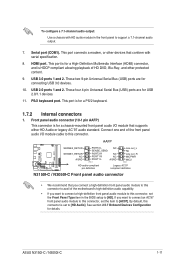
... MIC2 PIN 1 HD-audio-compliant pin definition Legacy AC'97 compliant definition N3150I-C / N3050I-C Front panel audio connector • We recommend that conform with HD audio module in the BIOS setup to support a 7.1-channel audio output. 7. USB 2.0 ports 1 and 2. Serial...By default, this connector. PS/2 keyboard port. See section 2.5.7 Onboard Devices Configuration for a PS/2 keyboard. 1.7.2 Internal connectors 1. ASUS N3150I-C / N3050I-C 1-11 This port connects a modem, or other protected content. 9. If you want to connect an AC'97 front panel audio ...
... MIC2 PIN 1 HD-audio-compliant pin definition Legacy AC'97 compliant definition N3150I-C / N3050I-C Front panel audio connector • We recommend that conform with HD audio module in the BIOS setup to support a 7.1-channel audio output. 7. USB 2.0 ports 1 and 2. Serial...By default, this connector. PS/2 keyboard port. See section 2.5.7 Onboard Devices Configuration for a PS/2 keyboard. 1.7.2 Internal connectors 1. ASUS N3150I-C / N3050I-C 1-11 This port connects a modem, or other protected content. 9. If you want to connect an AC'97 front panel audio ...

User Guide
Page 23
F_PANEL +PWR LED- The HD LED lights up when you turn on the system power, and blinks when the system is in the BIOS setup to this connector. To connect a LVDS monitor, set the IGD Flat Panel item in sleep mode. • Hard disk drive activity ... connector is for an LCD monitor that supports Low-voltage Differential Signaling (LVDS) interface. See section 2.5.3 SoC Configuration for the system power LED. ASUS N3150I-C / N3050I-C 1-15 Connect the chassis power LED cable to [LVDS]. LVDS connector (40-pin LVDS) This connector is disabled by default. System panel connector...
F_PANEL +PWR LED- The HD LED lights up when you turn on the system power, and blinks when the system is in the BIOS setup to this connector. To connect a LVDS monitor, set the IGD Flat Panel item in sleep mode. • Hard disk drive activity ... connector is for an LCD monitor that supports Low-voltage Differential Signaling (LVDS) interface. See section 2.5.3 SoC Configuration for the system power LED. ASUS N3150I-C / N3050I-C 1-15 Connect the chassis power LED cable to [LVDS]. LVDS connector (40-pin LVDS) This connector is disabled by default. System panel connector...

User Guide
Page 24
...Product introduction SATA6G_2 GND RSATA_TXP2 RSATA_TXN2 GND RSATA_RXN2 RSATA_RXP2 GND SATA6G_1 GND RSATA_TXP1 RSATA_TXN1 GND RSATA_RXN1 RSATA_RXP1 GND N3150I-C / N3050I-C SATA 6.0Gb/s connectors • To configure the default SATA type in BIOS, click Advanced Mode > Advanced tab > SATA Configuration > SATA Mode. • When using hot-plug and... NCQ, set the SATA Mode item in the BIOS to Serial ATA 6.0 Gb/s hard disk drive or optical drive via Serial ATA 6.0 Gb/s signal cables. Display panel power connector (2-pin...
...Product introduction SATA6G_2 GND RSATA_TXP2 RSATA_TXN2 GND RSATA_RXN2 RSATA_RXP2 GND SATA6G_1 GND RSATA_TXP1 RSATA_TXN1 GND RSATA_RXN1 RSATA_RXP1 GND N3150I-C / N3050I-C SATA 6.0Gb/s connectors • To configure the default SATA type in BIOS, click Advanced Mode > Advanced tab > SATA Configuration > SATA Mode. • When using hot-plug and... NCQ, set the SATA Mode item in the BIOS to Serial ATA 6.0 Gb/s hard disk drive or optical drive via Serial ATA 6.0 Gb/s signal cables. Display panel power connector (2-pin...
User Guide
Page 31
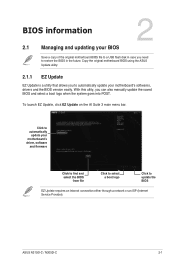
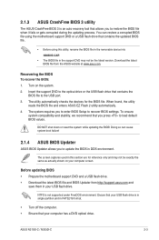
... the BIOS version easily. BIOS information 2 2.1 Managing and updating your BIOS Save a copy of the original motherboard BIOS file to a USB flash disk in the future. Copy the original motherboard BIOS using the ASUS Update... utility. 2.1.1 EZ Update EZ Update is a utility that allows you to restore the BIOS in case you can also manually update the saved BIOS and ... software and firmware Click to find and select the BIOS from file Click to select a boot logo Click to update the BIOS EZ Update requires an Internet connection either through a...
... the BIOS version easily. BIOS information 2 2.1 Managing and updating your BIOS Save a copy of the original motherboard BIOS file to a USB flash disk in the future. Copy the original motherboard BIOS using the ASUS Update... utility. 2.1.1 EZ Update EZ Update is a utility that allows you to restore the BIOS in case you can also manually update the saved BIOS and ... software and firmware Click to find and select the BIOS from file Click to select a boot logo Click to update the BIOS EZ Update requires an Internet connection either through a...
User Guide
Page 32
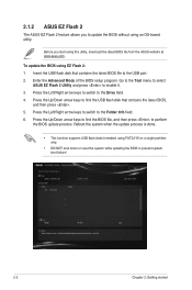
...Chapter 2: Getting started Press the Up/Down arrow keys to enable it. 3. To update the BIOS using EZ Flash 2: 1. Go to the Tool menu to select ASUS EZ Flash 2 Utility and press to find the BIOS file, and then press to the USB port. 2. Insert the USB flash disk that contains ... the Left/Right arrow keys to switch to update the BIOS without using an OS‑based utility. 2.1.2 ASUS EZ Flash 2 The ASUS EZ Flash 2 feature allows you start using this utility, download the latest BIOS file from the ASUS website at www.asus.com. Before you to the Folder Info field. 6. Enter...
...Chapter 2: Getting started Press the Up/Down arrow keys to enable it. 3. To update the BIOS using EZ Flash 2: 1. Go to the Tool menu to select ASUS EZ Flash 2 Utility and press to find the BIOS file, and then press to the USB port. 2. Insert the USB flash disk that contains ... the Left/Right arrow keys to switch to update the BIOS without using an OS‑based utility. 2.1.2 ASUS EZ Flash 2 The ASUS EZ Flash 2 feature allows you start using this utility, download the latest BIOS file from the ASUS website at www.asus.com. Before you to the Folder Info field. 6. Enter...
User Guide
Page 33
...; Prepare the motherboard support DVD and a USB flash drive. • Download the latest BIOS file and BIOS Updater from the ASUS website at www.asus.com. NTFS is not supported under FreeDOS environment. ASUS N3150I-C / N3050I-C 2-3 Download the latest BIOS file from http://support.asus.com and save them in FAT32/16 format. • Turn off the computer...
...; Prepare the motherboard support DVD and a USB flash drive. • Download the latest BIOS file and BIOS Updater from the ASUS website at www.asus.com. NTFS is not supported under FreeDOS environment. ASUS N3150I-C / N3050I-C 2-3 Download the latest BIOS file from http://support.asus.com and save them in FAT32/16 format. • Turn off the computer...

User Guide
Page 34
...the optical drive as the boot device. Welcome to enter FreeDOS prompt. On the BIOS Updater screen, press to switch from Drive C (optical drive) to the USB port. 2. boot: 5. C:/> d: D:/> Updating the BIOS file To update the BIOS file: 1. Please select boot device: and to move selection... then press to switch the disk from Files panel to boot using defaults P2: ST3808110AS (76319MB) aigo miniking (250MB) UEFI: (FAT) ASUS DRW-2014L1T(4458MB) P1: ASUS DRW-2014L1T(4458MB) UEFI: (FAT) aigo miniking (250MB) Enter Setup 4. Insert the USB flash drive with the latest...
...the optical drive as the boot device. Welcome to enter FreeDOS prompt. On the BIOS Updater screen, press to switch from Drive C (optical drive) to the USB port. 2. boot: 5. C:/> d: D:/> Updating the BIOS file To update the BIOS file: 1. Please select boot device: and to move selection... then press to switch the disk from Files panel to boot using defaults P2: ST3808110AS (76319MB) aigo miniking (250MB) UEFI: (FAT) ASUS DRW-2014L1T(4458MB) P1: ASUS DRW-2014L1T(4458MB) UEFI: (FAT) aigo miniking (250MB) Enter Setup 4. Insert the USB flash drive with the latest...

User Guide
Page 35
... feature is done, press to ensure system compatibility and stability. DO NOT shut down or reset the system while updating the BIOS to prevent system boot failaure. Select the Load Optimized Defaults item under the Exit BIOS menu. Select Yes then press . Drives panel ASUSTeK BIOS Updater for details. Restart your computer. ASUS N3150I-C / N3050I-C 2-5
... feature is done, press to ensure system compatibility and stability. DO NOT shut down or reset the system while updating the BIOS to prevent system boot failaure. Select the Load Optimized Defaults item under the Exit BIOS menu. Select Yes then press . Drives panel ASUSTeK BIOS Updater for details. Restart your computer. ASUS N3150I-C / N3050I-C 2-5
User Guide
Page 36
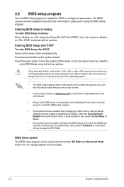
... include navigation keys and brief online help to boot after POST: Press ++ simultaneously. Entering BIOS Setup at startup To enter BIOS Setup at www.asus.com to download the latest BIOS file for reference purposes only, and may not exactly match what you do not press or , POST continues with its parameters. Select the...
... include navigation keys and brief online help to boot after POST: Press ++ simultaneously. Entering BIOS Setup at startup To enter BIOS Setup at www.asus.com to download the latest BIOS file for reference purposes only, and may not exactly match what you do not press or , POST continues with its parameters. Select the...

User Guide
Page 37
...CPU voltage output, CPU/chassis fan speed, and SATA information Selects the display language of the basic system information, and allows you enter the BIOS setup program. 2.2.1 EZ Mode By default, the EZ Mode screen appears when you to the Setup Mode item in section 2.7 Boot menu ...for entering the BIOS setup program can be changed. ASUS N3150I-C / N3050I-C 2-7 To access the Advanced Mode, click Advanced Mode(F7) or press . Refer to select the display language, system performance...
...CPU voltage output, CPU/chassis fan speed, and SATA information Selects the display language of the basic system information, and allows you enter the BIOS setup program. 2.2.1 EZ Mode By default, the EZ Mode screen appears when you to the Setup Mode item in section 2.7 Boot menu ...for entering the BIOS setup program can be changed. ASUS N3150I-C / N3050I-C 2-7 To access the Advanced Mode, click Advanced Mode(F7) or press . Refer to select the display language, system performance...

User Guide
Page 38
Refer to the following sections for experienced end-users to EZ Mode Displays the CPU/motherboard temperature, CPU and memory voltage output 2-8 Chapter 2: Getting started Quick Note MyFavorite Language Menu bar Hot Keys Sub-menu item Menu items General help Configuration fields Scroll bar Last modified settings Goes back to configure the BIOS settings. To access the EZ Mode, click EzMode(F7) or press . The figure below shows an example of the Advanced Mode. 2.2.2 Advanced Mode The Advanced Mode provides advanced options for the detailed configurations.
Refer to the following sections for experienced end-users to EZ Mode Displays the CPU/motherboard temperature, CPU and memory voltage output 2-8 Chapter 2: Getting started Quick Note MyFavorite Language Menu bar Hot Keys Sub-menu item Menu items General help Configuration fields Scroll bar Last modified settings Goes back to configure the BIOS settings. To access the EZ Mode, click EzMode(F7) or press . The figure below shows an example of the Advanced Mode. 2.2.2 Advanced Mode The Advanced Mode provides advanced options for the detailed configurations.

User Guide
Page 39
... Quick Note (F9) This button above the menu bar contains the navigation keys for your notes. Select frequentlyused BIOS settings and save it to display in your BIOS screen. ASUS N3150I-C / N3050I-C 2-9 Hot keys This button above the menu bar allows you to key in notes of the screen has ...the following keyboard functions: delete, cut, copy and paste. • You can select for the BIOS setup program. Use the navigation ...
... Quick Note (F9) This button above the menu bar contains the navigation keys for your notes. Select frequentlyused BIOS settings and save it to display in your BIOS screen. ASUS N3150I-C / N3050I-C 2-9 Hot keys This button above the menu bar allows you to key in notes of the screen has ...the following keyboard functions: delete, cut, copy and paste. • You can select for the BIOS setup program. Use the navigation ...
User Guide
Page 40
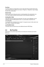
...configurable, you can change the value of the field opposite the item. To change the value of a field, select it to capture the BIOS screen and save and access your personal space where you can easily save it and press to display the other items on the screen. Last... Modified button This button shows the items that you last modified and saved in BIOS Setup. 2.3 My Favorites MyFavorites is your favorite BIOS items. 2-10 Chapter 2: Getting started Press the Up/Down arrow keys or / keys to display a list of options. Scroll...
...configurable, you can change the value of the field opposite the item. To change the value of a field, select it to capture the BIOS screen and save and access your personal space where you can easily save it and press to display the other items on the screen. Last... Modified button This button shows the items that you last modified and saved in BIOS Setup. 2.3 My Favorites MyFavorites is your favorite BIOS items. 2-10 Chapter 2: Getting started Press the Up/Down arrow keys or / keys to display a list of options. Scroll...

User Guide
Page 41
... as language and boot order • Configuration items such as favorite from the BIOS screen to save in MyFavorites screen. Adding items to view the saved BIOS items. ASUS N3150I-C / N3050I-C 2-11 Go to My Favorites menu to My Favorites To add BIOS items: 1. Click Exit (ESC) or press key to save as Memory SPD...
... as language and boot order • Configuration items such as favorite from the BIOS screen to save in MyFavorites screen. Adding items to view the saved BIOS items. ASUS N3150I-C / N3050I-C 2-11 Go to My Favorites menu to My Favorites To add BIOS items: 1. Click Exit (ESC) or press key to save as Memory SPD...


