User Guide
Page 3
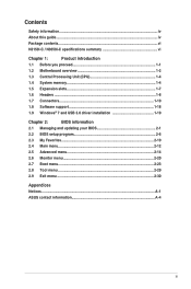
Contents Safety information...iv About this guide...iv Package contents...vi N3150I-C / N3050I-C specifications summary vi Chapter 1: Product introduction 1.1 Before you proceed 1-1 1.2 Motherboard overview 1-2 1.3 Central Processing Unit (CPU 1-4 1.4 System memory 1-4 1.5 Expansion slots 1-7 1.6 Headers...1-8 1.7 Connectors 1-10 1.8 Software support 1-...2-6 2.3 My Favorites 2-10 2.4 Main menu...2-12 2.5 Advanced menu 2-14 2.6 Monitor menu 2-20 2.7 Boot menu...2-23 2.8 Tool menu...2-29 2.9 Exit menu...2-30 Appendices Notices...A-1 ASUS contact information A-4 iii
Contents Safety information...iv About this guide...iv Package contents...vi N3150I-C / N3050I-C specifications summary vi Chapter 1: Product introduction 1.1 Before you proceed 1-1 1.2 Motherboard overview 1-2 1.3 Central Processing Unit (CPU 1-4 1.4 System memory 1-4 1.5 Expansion slots 1-7 1.6 Headers...1-8 1.7 Connectors 1-10 1.8 Software support 1-...2-6 2.3 My Favorites 2-10 2.4 Main menu...2-12 2.5 Advanced menu 2-14 2.6 Monitor menu 2-20 2.7 Boot menu...2-23 2.8 Tool menu...2-29 2.9 Exit menu...2-30 Appendices Notices...A-1 ASUS contact information A-4 iii
User Guide
Page 6
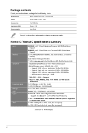
... CPU Memory Graphics Expansion slots Storage LAN Audio USB N3150I-C: Intel® Celeron® Quad-core Processor N3150 (Code Name: Braswell) N3050I-C: Intel® Celeron® Dual-core Processor N3050 (Code Name: Braswell) 2 x U-DIMM DDR3 1600/1066 MHz, Max 8GB,...Sub, LVDS - resolution of 1920 x 1200 @60Hz - Supports D-sub with HD audio module in the front panel to www.asus.com for the following items. Motherboard ASUS N3150I-C or N3050I-C motherboard Cables 2 x Serial ATA 6.0 Gb/s cables Accessories 1 x I/O Shields Application DVD Support DVD Documentation User Guide If ...
... CPU Memory Graphics Expansion slots Storage LAN Audio USB N3150I-C: Intel® Celeron® Quad-core Processor N3150 (Code Name: Braswell) N3050I-C: Intel® Celeron® Dual-core Processor N3050 (Code Name: Braswell) 2 x U-DIMM DDR3 1600/1066 MHz, Max 8GB,...Sub, LVDS - resolution of 1920 x 1200 @60Hz - Supports D-sub with HD audio module in the front panel to www.asus.com for the following items. Motherboard ASUS N3150I-C or N3050I-C motherboard Cables 2 x Serial ATA 6.0 Gb/s cables Accessories 1 x I/O Shields Application DVD Support DVD Documentation User Guide If ...

User Guide
Page 7
...DMI2.0, WfM2.0,SM BIOS 2.7, ACPI 2.0a, Multi-language BIOS, ASUS EZ Flash 2, ASUS CrashFree BIOS 3, My Favorites, Quick Note, Last Modified log, F12 PrintScreen, F3 Shortcut functions and ASUS DRAM SPD (Serial Presence Detect) memory information Wfm 2.0, DMI 2.0, ...174; 7 64-bit (continued on the next page) vii ASUS USB 3.0 Boost ASUS Quiet Thermal Solution - ASUS Fan Xpert - ASUS UEFI BIOS - ASUS MyLogo 2 - ASUS EZ-Flash 2 - ASUS Anti-surge Protection - N3150I-C / N3050I-C specifications summary ASUS Unique Features Back Panel I/O Ports Internal I/O Connectors BIOS features ...
...DMI2.0, WfM2.0,SM BIOS 2.7, ACPI 2.0a, Multi-language BIOS, ASUS EZ Flash 2, ASUS CrashFree BIOS 3, My Favorites, Quick Note, Last Modified log, F12 PrintScreen, F3 Shortcut functions and ASUS DRAM SPD (Serial Presence Detect) memory information Wfm 2.0, DMI 2.0, ...174; 7 64-bit (continued on the next page) vii ASUS USB 3.0 Boost ASUS Quiet Thermal Solution - ASUS Fan Xpert - ASUS UEFI BIOS - ASUS MyLogo 2 - ASUS EZ-Flash 2 - ASUS Anti-surge Protection - N3150I-C / N3050I-C specifications summary ASUS Unique Features Back Panel I/O Ports Internal I/O Connectors BIOS features ...

User Guide
Page 8
viii N3150I-C / N3050I-C specifications summary Support DVD Form factor Drivers ASUS utilities EZ Update Anti-virus software (OEM version) Mini-ITX Form Factor, 6.7" x 6.7" (17cm x 17cm) Specifications are subject to change without notice.
viii N3150I-C / N3050I-C specifications summary Support DVD Form factor Drivers ASUS utilities EZ Update Anti-virus software (OEM version) Mini-ITX Form Factor, 6.7" x 6.7" (17cm x 17cm) Specifications are subject to change without notice.

User Guide
Page 9
... as the power supply case, to avoid damaging them due to static electricity. • Hold components by the edges to the motherboard, peripherals, or components. ASUS N3150I-C / N3050I-C 1-1 Failure to do so may cause severe damage to avoid touching the ICs on them. • Whenever you uninstall any component, place it on...
... as the power supply case, to avoid damaging them due to static electricity. • Hold components by the edges to the motherboard, peripherals, or components. ASUS N3150I-C / N3050I-C 1-1 Failure to do so may cause severe damage to avoid touching the ICs on them. • Whenever you uninstall any component, place it on...
User Guide
Page 11
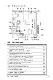
...3. USB 3.0 connector (20-1 pin USB3_34) 4. Display panel power connector (2-pin PANEL_SW) 15. TPM connector (14-1 pin TPM) ASUS N3150I-C / N3050I-C Mini PCIe SATA6G_1 SATA6G_2 N3150I-C N3050I-C DDR3_DIMM_A1 (64bit, 240-pin module) DDR3_DIMM_B1 (64bit, 240-pin module) EATX_PWR 17.0cm(6.7in) 5 7 Page 1-14 1-12 ...selector (3-pin VCC_PWR_SEL) 9. Front panel audio connector (10-1 pin AAFP) 18. N3150I-C: Intel® Celeron Quad-core Processor N3150 N3050I-C: Intel® Celeron Dual-core Processor N3050 5. Serial ATA 6.0Gb/s connectors (7-pin SATA6G_1, SATA6G_2) 8. USB 2.0 connector (10-...
...3. USB 3.0 connector (20-1 pin USB3_34) 4. Display panel power connector (2-pin PANEL_SW) 15. TPM connector (14-1 pin TPM) ASUS N3150I-C / N3050I-C Mini PCIe SATA6G_1 SATA6G_2 N3150I-C N3050I-C DDR3_DIMM_A1 (64bit, 240-pin module) DDR3_DIMM_B1 (64bit, 240-pin module) EATX_PWR 17.0cm(6.7in) 5 7 Page 1-14 1-12 ...selector (3-pin VCC_PWR_SEL) 9. Front panel audio connector (10-1 pin AAFP) 18. N3150I-C: Intel® Celeron Quad-core Processor N3150 N3050I-C: Intel® Celeron Dual-core Processor N3050 5. Serial ATA 6.0Gb/s connectors (7-pin SATA6G_1, SATA6G_2) 8. USB 2.0 connector (10-...
User Guide
Page 13
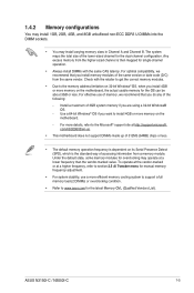
..., 4GB, and 8GB unbuffered non‑ECC DDR3 U-DIMMs into the DIMM sockets. • You may operate at a lower frequency than the vendor-marked value. ASUS N3150I-C / N3050I-C 1-5 com/kb/929605/en-us. • This motherboard does not support DIMMs made up of 512Mb (64MB) chips or less. • The default memory...
..., 4GB, and 8GB unbuffered non‑ECC DDR3 U-DIMMs into the DIMM sockets. • You may operate at a lower frequency than the vendor-marked value. ASUS N3150I-C / N3050I-C 1-5 com/kb/929605/en-us. • This motherboard does not support DIMMs made up of 512Mb (64MB) chips or less. • The default memory...
User Guide
Page 15
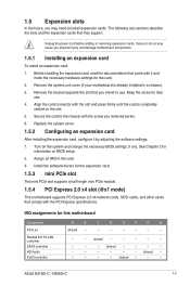
... and change the necessary BIOS settings, if any. shared - - - Before installing the expansion card, read the documentation that they support. Assign an IRQ to use . 4. ASUS N3150I-C / N3050I-C 1-7 Keep the screw for the card. 2. Align the card connector with the screw you removed earlier. 6. shared - - - - - shared - - - - - - - - See Chapter 2 for this motherboard Component...
... and change the necessary BIOS settings, if any. shared - - - Before installing the expansion card, read the documentation that they support. Assign an IRQ to use . 4. ASUS N3150I-C / N3050I-C 1-7 Keep the screw for the card. 2. Align the card connector with the screw you removed earlier. 6. shared - - - - - shared - - - - - - - - See Chapter 2 for this motherboard Component...

User Guide
Page 17
... a chassis component is then generated as a chassis intrusion event. Display panel backlight power selector (3-pin BLKT_PWR_SEL) N3150I-C N3050I-C BLKT_PWR_SEL 12 23 12V 5V (Default) N3150I-C / N3050I-C Display panel backlight power selection Pins 1-2 (Default) 2-3 Setting 12V 5V ASUS N3150I-C / N3050I-C 1-9 3. The chassis intrusion sensor or switch sends a high-level signal to this connector. CHASSIS N3150I...
... a chassis component is then generated as a chassis intrusion event. Display panel backlight power selector (3-pin BLKT_PWR_SEL) N3150I-C N3050I-C BLKT_PWR_SEL 12 23 12V 5V (Default) N3150I-C / N3050I-C Display panel backlight power selection Pins 1-2 (Default) 2-3 Setting 12V 5V ASUS N3150I-C / N3050I-C 1-9 3. The chassis intrusion sensor or switch sends a high-level signal to this connector. CHASSIS N3150I...
User Guide
Page 19
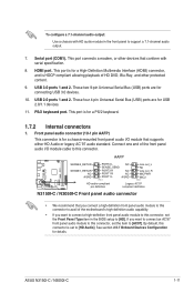
... L AGND PIN 1 Line out_L NC Line out_R MICPWR MIC2 PIN 1 HD-audio-compliant pin definition Legacy AC'97 compliant definition N3150I-C / N3050I-C Front panel audio connector • We recommend that you connect a high-definition front panel audio module to this connector to avail of the ... four 4-pin Universal Serial Bus (USB) ports are for USB 2.0/1.1 devices. 11. This port connects a modem, or other protected content. 9. ASUS N3150I-C / N3050I-C 1-11 PS/2 keyboard port. Front panel audio connector (10-1 pin AAFP) This connector is set the Front Panel Type item in the front...
... L AGND PIN 1 Line out_L NC Line out_R MICPWR MIC2 PIN 1 HD-audio-compliant pin definition Legacy AC'97 compliant definition N3150I-C / N3050I-C Front panel audio connector • We recommend that you connect a high-definition front panel audio module to this connector to avail of the ... four 4-pin Universal Serial Bus (USB) ports are for USB 2.0/1.1 devices. 11. This port connects a modem, or other protected content. 9. ASUS N3150I-C / N3050I-C 1-11 PS/2 keyboard port. Front panel audio connector (10-1 pin AAFP) This connector is set the Front Panel Type item in the front...

User Guide
Page 21
...GND +3 Volts +3 Volts GND +5 Volts +5 Volts +5 Volts -5 Volts GND GND GND PSON# GND -12 Volts +3 Volts GND GND N3150I-C / N3050I-C ATX power connectors • For a fully configured system, we recommend that complies with more power-consuming devices. The power supply plugs are for details.... down firmly until the connectors completely fit. Otherwise, the system will not boot up if the power is purchased separately. ASUS N3150I-C / N3050I-C 1-13 com/PowerSupplyCalculator/PSCalculator.aspx?SLanguage=en-us for ATX power supply plugs. ATX power connectors (24-pin EATXPWR,...
...GND +3 Volts +3 Volts GND +5 Volts +5 Volts +5 Volts -5 Volts GND GND GND PSON# GND -12 Volts +3 Volts GND GND N3150I-C / N3050I-C ATX power connectors • For a fully configured system, we recommend that complies with more power-consuming devices. The power supply plugs are for details.... down firmly until the connectors completely fit. Otherwise, the system will not boot up if the power is purchased separately. ASUS N3150I-C / N3050I-C 1-13 com/PowerSupplyCalculator/PSCalculator.aspx?SLanguage=en-us for ATX power supply plugs. ATX power connectors (24-pin EATXPWR,...

User Guide
Page 23
N3150I-C N3050I-C LVDS PIN 1 N3150I-C / N3050I-C LVDS connector The LVDS output is for the chassis-mounted reset button for system reboot without turning off button (2-pin PWRBTN) This connector is for ... the HDD Activity LED cable to the HDD. • ATX power button/soft-off the system power. 9. ASUS N3150I-C / N3050I-C 1-15 LVDS connector (40-pin LVDS) This connector is for the HDD Activity LED. RESET N3150I-C / N3050I-C System panel connector • System power LED (2-pin PWRLED) This 2-pin connector is for details. The...
N3150I-C N3050I-C LVDS PIN 1 N3150I-C / N3050I-C LVDS connector The LVDS output is for the chassis-mounted reset button for system reboot without turning off button (2-pin PWRBTN) This connector is for ... the HDD Activity LED cable to the HDD. • ATX power button/soft-off the system power. 9. ASUS N3150I-C / N3050I-C 1-15 LVDS connector (40-pin LVDS) This connector is for the HDD Activity LED. RESET N3150I-C / N3050I-C System panel connector • System power LED (2-pin PWRLED) This 2-pin connector is for details. The...
User Guide
Page 25
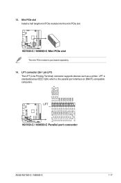
...as IEEE 1284, which is the parallel port interface on IBM PC-compatible computers. LPT PIN 1 N3150I-C / N3050I-C Parallel port connector O_LPT_XAFD#_R O_LPT_ERROR#_R O_LPT_XINIT#_R O_LPT_XSLIN#_R GND GND GND GND GND GND GND GND ...O_LPT_XSTB#_R O_LPT_XPD0_R O_LPT_XPD1_R O_LPT_XPD2_R O_LPT_XPD3_R O_LPT_XPD4_R O_LPT_XPD5_R O_LPT_XPD6_R O_LPT_XPD7_R O_LPT_ACK#_R O_LPT_BUSY_R O_LPT_PE_R O_LPT_SLCT_R N3150I-C N3050I-C ASUS N3150I-C / N3050I-C 1-17 N3150I-C N3050I-C 13. N3150I-C / N3050I-C Mini PCIe slot The mini PCIe module is standardized as a printer. Mini PCIe slot Install...
...as IEEE 1284, which is the parallel port interface on IBM PC-compatible computers. LPT PIN 1 N3150I-C / N3050I-C Parallel port connector O_LPT_XAFD#_R O_LPT_ERROR#_R O_LPT_XINIT#_R O_LPT_XSLIN#_R GND GND GND GND GND GND GND GND ...O_LPT_XSTB#_R O_LPT_XPD0_R O_LPT_XPD1_R O_LPT_XPD2_R O_LPT_XPD3_R O_LPT_XPD4_R O_LPT_XPD5_R O_LPT_XPD6_R O_LPT_XPD7_R O_LPT_ACK#_R O_LPT_BUSY_R O_LPT_PE_R O_LPT_SLCT_R N3150I-C N3050I-C ASUS N3150I-C / N3050I-C 1-17 N3150I-C N3050I-C 13. N3150I-C / N3050I-C Mini PCIe slot The mini PCIe module is standardized as a printer. Mini PCIe slot Install...

User Guide
Page 27
... Windows® 7 64-bit installation DVD into a SATA ODD on your Braswell series platform. 3. Power on your Braswell series platform. 4. ASUS N3150I-C / N3050I-C 1-19 It is a guide on preloading USB 3.0 drivers and installing Windows® 7 64-bit. Select the USB ODD or USB storage... device as the boot device. Requirement: • 1 x ASUS support DVD • 1 x Windows® 7 64-bit installation source • 1 x SATA ODD • 1 x ...
... Windows® 7 64-bit installation DVD into a SATA ODD on your Braswell series platform. 3. Power on your Braswell series platform. 4. ASUS N3150I-C / N3050I-C 1-19 It is a guide on preloading USB 3.0 drivers and installing Windows® 7 64-bit. Select the USB ODD or USB storage... device as the boot device. Requirement: • 1 x ASUS support DVD • 1 x Windows® 7 64-bit installation source • 1 x SATA ODD • 1 x ...

User Guide
Page 29
Requirement: • 1 x ASUS support DVD • 1 x Windows® 7 64-bit installation source • 1 x Working system (PC or notebook) • 1 x SATA ODD 1. Edit the ISO file and add both "... DVD to your system and press F8 during POST (Power-On Self Test) to create a modified Windows® 7 64-bit installation DVD. 5. ASUS N3150I-C / N3050I-C 1-21 Copy both "Auto_Unattend.xml" and "Auto_Unattend" folder into an ODD on your system. 3. Burn this ISO file onto an empty DVD to enter the ...
Requirement: • 1 x ASUS support DVD • 1 x Windows® 7 64-bit installation source • 1 x Working system (PC or notebook) • 1 x SATA ODD 1. Edit the ISO file and add both "... DVD to your system and press F8 during POST (Power-On Self Test) to create a modified Windows® 7 64-bit installation DVD. 5. ASUS N3150I-C / N3050I-C 1-21 Copy both "Auto_Unattend.xml" and "Auto_Unattend" folder into an ODD on your system. 3. Burn this ISO file onto an empty DVD to enter the ...
User Guide
Page 31
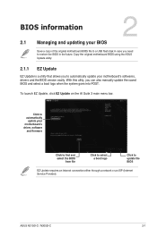
ASUS N3150I-C / N3050I-C 2-1 Copy the original motherboard BIOS using the ASUS Update utility. 2.1.1 EZ Update EZ Update is a utility that allows you to restore the BIOS in case you need to automatically update your motherboard's driver, ...
ASUS N3150I-C / N3050I-C 2-1 Copy the original motherboard BIOS using the ASUS Update utility. 2.1.1 EZ Update EZ Update is a utility that allows you to restore the BIOS in case you need to automatically update your motherboard's driver, ...
User Guide
Page 33
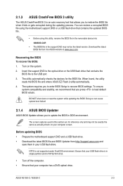
... the motherboard support DVD and a USB flash drive. • Download the latest BIOS file and BIOS Updater from the ASUS website at www.asus.com. ASUS N3150I-C / N3050I-C 2-3 NTFS is not supported under FreeDOS environment. Ensure that your USB flash drive is in single partition and in DOS... environment. When found, the utility reads the BIOS file and enters ASUS EZ Flash 2 utility automatically. 4. Doing so can restore ...
... the motherboard support DVD and a USB flash drive. • Download the latest BIOS file and BIOS Updater from the ASUS website at www.asus.com. ASUS N3150I-C / N3050I-C 2-3 NTFS is not supported under FreeDOS environment. Ensure that your USB flash drive is in single partition and in DOS... environment. When found, the utility reads the BIOS file and enters ASUS EZ Flash 2 utility automatically. 4. Doing so can restore ...

User Guide
Page 35
... NOT shut down or reset the system while updating the BIOS to confirm the BIOS update. ASUS N3150I-C / N3050I-C 2-5 Restart your computer. See section 2.9 Exit Menu for DOS V1.30 [2014/01/01] Current ROM BOARD: N3050I-C VER: 0210 (H :00 B :00) DATE: 04/01/2015 PATH: C:\ Update ROM BOARD: Unknown VER...: Unknown DATE: Unknown C: FORMAN~1 D: N3050I-C.CAP 8390656 2015-04-01 21:14:34 Note [Enter] Select or Load [Up/Down/Home...
... NOT shut down or reset the system while updating the BIOS to confirm the BIOS update. ASUS N3150I-C / N3050I-C 2-5 Restart your computer. See section 2.9 Exit Menu for DOS V1.30 [2014/01/01] Current ROM BOARD: N3050I-C VER: 0210 (H :00 B :00) DATE: 04/01/2015 PATH: C:\ Update ROM BOARD: Unknown VER...: Unknown DATE: Unknown C: FORMAN~1 D: N3050I-C.CAP 8390656 2015-04-01 21:14:34 Note [Enter] Select or Load [Up/Down/Home...

User Guide
Page 37
The default screen for details. ASUS N3150I-C / N3050I-C 2-7 Refer to the Setup Mode item in section 2.7 Boot menu for entering the BIOS setup program can be changed. Displays the CPU/motherboard temperature, CPU ...
The default screen for details. ASUS N3150I-C / N3050I-C 2-7 Refer to the Setup Mode item in section 2.7 Boot menu for entering the BIOS setup program can be changed. Displays the CPU/motherboard temperature, CPU ...

User Guide
Page 39
... functions For selecting the exit options and loading default settings Menu items The highlighted item on any menu screen means that the item has a submenu. ASUS N3150I-C / N3050I-C 2-9 MyFavorites (F3) This button above the menu bar contains the navigation keys for more information.
... functions For selecting the exit options and loading default settings Menu items The highlighted item on any menu screen means that the item has a submenu. ASUS N3150I-C / N3050I-C 2-9 MyFavorites (F3) This button above the menu bar contains the navigation keys for more information.


