User Manual
Page 3
Contents Notices...viii Safety information ix About this guide x Maximus II GENE specifications summary xii Chapter 1: Product introduction 1.1 Welcome 1-1 1.2 Package contents 1-1 1.3 Special features 1-2 1.3.1 Product highlights 1-2 1.3.2 ROG Intelligent Performance & Overclocking features... 1-3 1.3.3 ROG unique features 1-4 1.3.4 ASUS special features 1-5 Chapter 2: Hardware information 2.1 Before you proceed 2-1 2.2 Motherboard overview 2-6 2.2.1 Motherboard layout 2-6 2.2.2 Layout contents 2-7 2.2.3 Placement direction 2-8 2.2.4 Screw holes 2-8 2.3 Central Processing Unit ...
Contents Notices...viii Safety information ix About this guide x Maximus II GENE specifications summary xii Chapter 1: Product introduction 1.1 Welcome 1-1 1.2 Package contents 1-1 1.3 Special features 1-2 1.3.1 Product highlights 1-2 1.3.2 ROG Intelligent Performance & Overclocking features... 1-3 1.3.3 ROG unique features 1-4 1.3.4 ASUS special features 1-5 Chapter 2: Hardware information 2.1 Before you proceed 2-1 2.2 Motherboard overview 2-6 2.2.1 Motherboard layout 2-6 2.2.2 Layout contents 2-7 2.2.3 Placement direction 2-8 2.2.4 Screw holes 2-8 2.3 Central Processing Unit ...

User Manual
Page 9
...disconnect all cables are correctly connected and the power cables are using an adapter or extension cord. Operation safety • Before installing the motherboard and adding devices on a stable surface. • If you detect any area where it may become wet. • Place the product... on it by yourself. DO NOT throw the motherboard in municipal waste. Contact a qualified service technician or your area. If you encounter technical problems with the product, contact a qualified service technician...
...disconnect all cables are correctly connected and the power cables are using an adapter or extension cord. Operation safety • Before installing the motherboard and adding devices on a stable surface. • If you detect any area where it may become wet. • Place the product... on it by yourself. DO NOT throw the motherboard in municipal waste. Contact a qualified service technician or your area. If you encounter technical problems with the product, contact a qualified service technician...

User Manual
Page 10
.... • Chapter 5: Multiple GPU technology support This chapter describes how to perform when installing system components. ASUS websites The ASUS website provides updated information on the motherboard. • Chapter 3: BIOS setup This chapter tells how to the ASUS contact information. 2. How this guide This user guide contains the information you have been added by...
.... • Chapter 5: Multiple GPU technology support This chapter describes how to perform when installing system components. ASUS websites The ASUS website provides updated information on the motherboard. • Chapter 3: BIOS setup This chapter tells how to the ASUS contact information. 2. How this guide This user guide contains the information you have been added by...

User Manual
Page 15
Chapter 1: 1Product introduction This chapter describes the motherboard features and the new technologies it supports.
Chapter 1: 1Product introduction This chapter describes the motherboard features and the new technologies it supports.

User Manual
Page 17
... Kit 1 x I/O Shield 1 x Cable ties 1 x ROG theme label Application DVD ROG motherboard support DVD Documentation User guide If any of ASUS quality motherboards! 1.1 Welcome! ROG Maximus II GENE 1-1 Before you for the following items. Motherboard ROG Maximus II GENE Cables 1 �x �U���lt�r��a��D���M���A���1�...
... Kit 1 x I/O Shield 1 x Cable ties 1 x ROG theme label Application DVD ROG motherboard support DVD Documentation User guide If any of ASUS quality motherboards! 1.1 Welcome! ROG Maximus II GENE 1-1 Before you for the following items. Motherboard ROG Maximus II GENE Cables 1 �x �U���lt�r��a��D���M���A���1�...

User Manual
Page 18
...gamers to boost system performance, eliminating bottlenecks with 1600 / 1333 / 1066 / 800 MHz FSB. Green ASUS This motherboard and its packaging comply with the ASUS vision of creating environment-friendly and recyclable products/packaging to safeguard consumers' health while minimizing the impact on the...make your system memory to join in. Intel® Core™2 Extreme / Core™ 2 Quad / Core™2 Duo Processor Support This motherboard supports the latest Intel® Core™ 2 Extreme / Core™ 2 Quad / Core™ 2 Duo processors in the new 45nm manufacturing...
...gamers to boost system performance, eliminating bottlenecks with 1600 / 1333 / 1066 / 800 MHz FSB. Green ASUS This motherboard and its packaging comply with the ASUS vision of creating environment-friendly and recyclable products/packaging to safeguard consumers' health while minimizing the impact on the...make your system memory to join in. Intel® Core™2 Extreme / Core™ 2 Quad / Core™2 Duo Processor Support This motherboard supports the latest Intel® Core™ 2 Extreme / Core™ 2 Quad / Core™ 2 Duo processors in the new 45nm manufacturing...

User Manual
Page 19
...control and efficiency. See page 3-10 and 4-25 for instant upgrade! Any memory is the fastest memory booting solution today. ROG Maximus II GENE 1-3 Ever wish that give you system up and running in no more expansive CPU? Worry no time. ATI CrossFireX Technology ATI's... increases fun during overclocking for double speed and bandwidth which enables several ROG highlighted functions that you want . MemOK! Double Bandwidth This motherboard supports the latest PCIe 2.0 device for PC enthusiasts and it comes to computer upgrades. PCIe 2.0 Double Speed; The technology is a...
...control and efficiency. See page 3-10 and 4-25 for instant upgrade! Any memory is the fastest memory booting solution today. ROG Maximus II GENE 1-3 Ever wish that give you system up and running in no more expansive CPU? Worry no time. ATI CrossFireX Technology ATI's... increases fun during overclocking for double speed and bandwidth which enables several ROG highlighted functions that you want . MemOK! Double Bandwidth This motherboard supports the latest PCIe 2.0 device for PC enthusiasts and it comes to computer upgrades. PCIe 2.0 Double Speed; The technology is a...
User Manual
Page 20
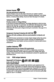
... LED Friendly reminder on Voltage Settings In the pursuit of a tachometer, the Voltiminder LED displays the voltage status for overclockers. It helps overclockers enjoy the motherboard's ultimate OC capabilities and benchmark scores. 1.3.3 ROG unique features SupremeFX X-Fi features Listen with burn proof protection to the gamers of SupremeFX and sound effect...
... LED Friendly reminder on Voltage Settings In the pursuit of a tachometer, the Voltiminder LED displays the voltage status for overclockers. It helps overclockers enjoy the motherboard's ultimate OC capabilities and benchmark scores. 1.3.3 ROG unique features SupremeFX X-Fi features Listen with burn proof protection to the gamers of SupremeFX and sound effect...

User Manual
Page 22
...home offices. function. 1-6 Chapter 1: Product Introduction Profile The motherboard features the ASUS O.C. C.P.R. (CPU Parameter Recall) When the system hangs due to overclocking failure, there is based on advanced antivirus technologies. ASUS Q-Connector The ASUS Q-Connector allows you to connect or disconnect chassis front panel cables... in one easy step with one cable at a time, making connection quick and accurate. ASUS EZ Flash 2 EZ Flash 2 is renowned for details. Kaspersky® Anti-Virus The best protection from viruses and spyware ...
...home offices. function. 1-6 Chapter 1: Product Introduction Profile The motherboard features the ASUS O.C. C.P.R. (CPU Parameter Recall) When the system hangs due to overclocking failure, there is based on advanced antivirus technologies. ASUS Q-Connector The ASUS Q-Connector allows you to connect or disconnect chassis front panel cables... in one easy step with one cable at a time, making connection quick and accurate. ASUS EZ Flash 2 EZ Flash 2 is renowned for details. Kaspersky® Anti-Virus The best protection from viruses and spyware ...

User Manual
Page 23
It Chapter 2: includes description of the jumpers and connectors on the motherboard. 2 Hardware information This chapter lists the hardware setup procedures that you have to perform when installing system components.
It Chapter 2: includes description of the jumpers and connectors on the motherboard. 2 Hardware information This chapter lists the hardware setup procedures that you have to perform when installing system components.

User Manual
Page 24
Chapter summary 2 2.1 Before you proceed 2-1 2.2 Motherboard overview 2-6 2.3 Central Processing Unit (CPU 2-9 2.4 System memory 2-15 2.5 Expansion slots 2-25 2.6 Jumper 2-29 2.7 Connectors 2-30 2.8 Starting up for the first time 2-47 2.9 Turning off the computer 2-48 ROG Maximus II GENE
Chapter summary 2 2.1 Before you proceed 2-1 2.2 Motherboard overview 2-6 2.3 Central Processing Unit (CPU 2-9 2.4 System memory 2-15 2.5 Expansion slots 2-25 2.6 Jumper 2-29 2.7 Connectors 2-30 2.8 Starting up for the first time 2-47 2.9 Turning off the computer 2-48 ROG Maximus II GENE

User Manual
Page 25
ROG Maximus II GENE 2-1 Failure to do so may cause severe damage to avoid touching the ICs on them. • Whenever you uninstall any component, place it on a grounded ..., such as the power supply case, before handling components to avoid damaging them due to static electricity. • Hold components by the edges to the motherboard, peripherals, and/or components. 2.1 Before you proceed Take note of the following precautions before you install or remove any component, ensure that came with the...
ROG Maximus II GENE 2-1 Failure to do so may cause severe damage to avoid touching the ICs on them. • Whenever you uninstall any component, place it on a grounded ..., such as the power supply case, before handling components to avoid damaging them due to static electricity. • Hold components by the edges to the motherboard, peripherals, and/or components. 2.1 Before you proceed Take note of the following precautions before you install or remove any component, ensure that came with the...

User Manual
Page 26
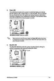
Onboard LEDs The motherboard comes with LEDs that indicate the voltage conditions of the CPU LED and the table below for power status. you can select the voltage to 3.3 ...
Onboard LEDs The motherboard comes with LEDs that indicate the voltage conditions of the CPU LED and the table below for power status. you can select the voltage to 3.3 ...

User Manual
Page 28
The LED does not light up when there is no hard disk drive connected to the illustration below for the location of the memory LED and the table below for LED definition. Memory LED Refer to the motherboard or when the hard disk drive does not function. 2-4 Chapter 2: Hardware information Hard Disk LED The hard disk LED is being written into or read from the hard disk drive. Normal (green) DRAM Bus Voltage 1.80000-1.99875 High (yellow) 2.01200-2.60825 Crazy (red) 2.62150-3.40325 4. 3. It blinks when data is designed to indicate the hard disk activity.
The LED does not light up when there is no hard disk drive connected to the illustration below for the location of the memory LED and the table below for LED definition. Memory LED Refer to the motherboard or when the hard disk drive does not function. 2-4 Chapter 2: Hardware information Hard Disk LED The hard disk LED is being written into or read from the hard disk drive. Normal (green) DRAM Bus Voltage 1.80000-1.99875 High (yellow) 2.01200-2.60825 Crazy (red) 2.62150-3.40325 4. 3. It blinks when data is designed to indicate the hard disk activity.
User Manual
Page 29
...that the system is loading failsafe settings for memory compatibility after pressing the MemOK! 5. ROG Maximus II GENE 2-5 This is ready to indicate that you press the power-on switch. 6. MemOK! Power LED The motherboard comes with a power-on switch. LED blinks while the system is ON, in sleep mode..., or in any motherboard component. The illustration below shows the location of the onboard power-on switch that...
...that the system is loading failsafe settings for memory compatibility after pressing the MemOK! 5. ROG Maximus II GENE 2-5 This is ready to indicate that you press the power-on switch. 6. MemOK! Power LED The motherboard comes with a power-on switch. LED blinks while the system is ON, in sleep mode..., or in any motherboard component. The illustration below shows the location of the onboard power-on switch that...

User Manual
Page 30
2.2 Motherboard overview 2.2.1 Motherboard layout 2-6 Chapter 2: Hardware information
2.2 Motherboard overview 2.2.1 Motherboard layout 2-6 Chapter 2: Hardware information

User Manual
Page 32
DO NOT overtighten the screws! The edge with external ports goes to the rear part of the chassis 2-8 Chapter 2: Hardware information Doing so can damage the motherboard. Place this side towards the rear of the chassis as indicated in the image below. 2.2.4 Screw holes Place eight (8) screws into the chassis in the correct orientation. 2.2.3 Placement direction When installing the motherboard, ensure that you place it into the holes indicated by circles to secure the motherboard to the chassis.
DO NOT overtighten the screws! The edge with external ports goes to the rear part of the chassis 2-8 Chapter 2: Hardware information Doing so can damage the motherboard. Place this side towards the rear of the chassis as indicated in the image below. 2.2.4 Screw holes Place eight (8) screws into the chassis in the correct orientation. 2.2.3 Placement direction When installing the motherboard, ensure that you place it into the holes indicated by circles to secure the motherboard to the chassis.
User Manual
Page 33
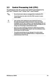
ROG Maximus II GENE 2-9 Contact your retailer immediately if the PnP cap is on the LGA775 socket. • The product warranty does not cover damage to the PnP cap/socket contacts/motherboard components. 2.3 Central Processing Unit (CPU) The motherboard comes with the cap on...removal of repair only if the damage is shipment/transit-related. • Keep the cap after installing the motherboard. ASUS will process Return Merchandise Authorization (RMA) requests only if the motherboard comes with a surface mount LGA775 socket designed for the Intel® Core™ 2 Extreme / Core...
ROG Maximus II GENE 2-9 Contact your retailer immediately if the PnP cap is on the LGA775 socket. • The product warranty does not cover damage to the PnP cap/socket contacts/motherboard components. 2.3 Central Processing Unit (CPU) The motherboard comes with the cap on...removal of repair only if the damage is shipment/transit-related. • Keep the cap after installing the motherboard. ASUS will process Return Merchandise Authorization (RMA) requests only if the motherboard comes with a surface mount LGA775 socket designed for the Intel® Core™ 2 Extreme / Core...

User Manual
Page 34
... CPU, ensure that the cam box is facing towards you are installing a CPU. Lift the load plate with your left (B) until it is on the motherboard. PnP cap Load plate 4B 4A 3 2-10 Chapter 2: Hardware information Press the load lever with your thumb and forefinger to remove (4B). To p re ve...
... CPU, ensure that the cam box is facing towards you are installing a CPU. Lift the load plate with your left (B) until it is on the motherboard. PnP cap Load plate 4B 4A 3 2-10 Chapter 2: Hardware information Press the load lever with your thumb and forefinger to remove (4B). To p re ve...

User Manual
Page 36
Close the load plate (A), then push the load lever (B) until it snaps into A the retention tab. B The motherboard supports Intel® LGA775 processors with the Intel® Enhanced Memory 64 Technology (EM64T), Enhanced Intel SpeedStep® Technology (EIST), and Hyper-Threading Technology. Refer to the Appendix for more information on these CPU features. 2-12 Chapter 2: Hardware information 7.
Close the load plate (A), then push the load lever (B) until it snaps into A the retention tab. B The motherboard supports Intel® LGA775 processors with the Intel® Enhanced Memory 64 Technology (EM64T), Enhanced Intel SpeedStep® Technology (EIST), and Hyper-Threading Technology. Refer to the Appendix for more information on these CPU features. 2-12 Chapter 2: Hardware information 7.


