MEL-B User Manual
Page 2
...the digit before and after the period of Adobe Systems Incorporated. For previous or updated manuals, BIOS, drivers, or product release information, contact ASUS at http://www.asus.com.tw or through any of the means indicated on the product itself. All Rights Reserved....Microsoft Corporation. • Adobe and Acrobat are registered trademarks of the manual revision number. Product Name: ASUS MEL-B Manual Revision: 1.00 E336 Release Date: January 1999 2 ASUS MEL-B User's Manual SPECIFICATIONS AND INFORMATION CONTAINED IN THIS MANUAL ARE FURNISHED FOR INFORMATIONAL USE ONLY, AND ARE...
...the digit before and after the period of Adobe Systems Incorporated. For previous or updated manuals, BIOS, drivers, or product release information, contact ASUS at http://www.asus.com.tw or through any of the means indicated on the product itself. All Rights Reserved....Microsoft Corporation. • Adobe and Acrobat are registered trademarks of the manual revision number. Product Name: ASUS MEL-B Manual Revision: 1.00 E336 Release Date: January 1999 2 ASUS MEL-B User's Manual SPECIFICATIONS AND INFORMATION CONTAINED IN THIS MANUAL ARE FURNISHED FOR INFORMATIONAL USE ONLY, AND ARE...

MEL-B User Manual
Page 4
... Features Setup 44 Power Management Setup 47 Details of the ASUS MEL-B Motherboard 11 III. BIOS SETUP 34 Main Menu 34 Managing and Updating Your Motherboard's BIOS 36 6. System Memory (DIMM 17 DIMM Memory Installation 18 3. FEATURES 8 The ASUS MEL-B Motherboard 8 Parts of Power Management Setup 47 4 ASUS MEL-B User's Manual Motherboard Settings 14 2. Central Processing Unit (CPU...
... Features Setup 44 Power Management Setup 47 Details of the ASUS MEL-B Motherboard 11 III. BIOS SETUP 34 Main Menu 34 Managing and Updating Your Motherboard's BIOS 36 6. System Memory (DIMM 17 DIMM Memory Installation 18 3. FEATURES 8 The ASUS MEL-B Motherboard 8 Parts of Power Management Setup 47 4 ASUS MEL-B User's Manual Motherboard Settings 14 2. Central Processing Unit (CPU...

MEL-B User Manual
Page 5
CONTENTS PNP and PCI Setup 50 Details of PNP and PCI Setup 50 Load BIOS Defaults 52 Load Setup Defaults 52 Supervisor Password and User Password 53 IDE HDD Auto Detection 54 Save & Exit Setup 55 Exit Without Saving 55 V. SOFTWARE REFERENCE 69 APPENDIX 83 ASUS MEL-B User's Manual 5 SOFTWARE SETUP 57 VI.
CONTENTS PNP and PCI Setup 50 Details of PNP and PCI Setup 50 Load BIOS Defaults 52 Load Setup Defaults 52 Supervisor Password and User Password 53 IDE HDD Auto Detection 54 Save & Exit Setup 55 Exit Without Saving 55 V. SOFTWARE REFERENCE 69 APPENDIX 83 ASUS MEL-B User's Manual 5 SOFTWARE SETUP 57 VI.

MEL-B User Manual
Page 7
...drivers and utilities (1) This Motherboard User's Manual ASUS IrDA-compliant infrared module (optional) ASUS USB/MIR module (optional) ASUS CIDB chassis sensor module (optional) ASUS PCI-L101 Wake-On-LAN 10/100 Fast Ethernet Card (optional) ASUS MEL-B User's Manual 7 If you discover damaged or... Setup Information on setting up the motherboard IV. Hardware Setup Instructions on setting up the BIOS software V. INTRODUCTION How this product III. Introduction Manual information and checklist II. I . BIOS Setup Instructions on setting up the included support software VI.
...drivers and utilities (1) This Motherboard User's Manual ASUS IrDA-compliant infrared module (optional) ASUS USB/MIR module (optional) ASUS CIDB chassis sensor module (optional) ASUS PCI-L101 Wake-On-LAN 10/100 Fast Ethernet Card (optional) ASUS MEL-B User's Manual 7 If you discover damaged or... Setup Information on setting up the motherboard IV. Hardware Setup Instructions on setting up the BIOS software V. INTRODUCTION How this product III. Introduction Manual information and checklist II. I . BIOS Setup Instructions on setting up the included support software VI.

MEL-B User Manual
Page 8
... Features Intel's 440LX AGPset with a 66MHz Front Side Bus and I/O subsystems. • Enhanced ACPI & Anti-Boot Virus BIOS: Programmable BIOS (Flash EEPROM), offering enhanced ACPI for Windows 98 compatibility, built-in firmware-based virus protection, and autodetection of most devices ...Easy Installation: Equipped with BIOS that supports autodetection of hard drives, PS/2 mouse, and Plug and Play devices to -access DIP switches make changing CPU and onboard feature settings a snap. 8 ASUS MEL-B User's Manual FEATURES The ASUS MEL-B Motherboard The ASUS MEL-B motherboard is carefully designed...
... Features Intel's 440LX AGPset with a 66MHz Front Side Bus and I/O subsystems. • Enhanced ACPI & Anti-Boot Virus BIOS: Programmable BIOS (Flash EEPROM), offering enhanced ACPI for Windows 98 compatibility, built-in firmware-based virus protection, and autodetection of most devices ...Easy Installation: Equipped with BIOS that supports autodetection of hard drives, PS/2 mouse, and Plug and Play devices to -access DIP switches make changing CPU and onboard feature settings a snap. 8 ASUS MEL-B User's Manual FEATURES The ASUS MEL-B Motherboard The ASUS MEL-B motherboard is carefully designed...

MEL-B User Manual
Page 9
... for Plug and Play compatibility and power management for Windows 95/98/NT. • SDRAM Optimized Performance: ASUS smart series motherboards support the new generation memory, Synchronous Dynamic Random Access Memory (SDRAM), which increases the data...rates up to CPU. • PC'98 Compliant: Both the BIOS and hardware levels of Windows 95 must be ready around the clock, yet satisfy all ASUS smart series motherboards. FEATURES Features II. The best of all system...operating systems (OS) supporting OS Direct Power Management (OSPM) functionality. II. ASUS MEL-B User's Manual 9
... for Plug and Play compatibility and power management for Windows 95/98/NT. • SDRAM Optimized Performance: ASUS smart series motherboards support the new generation memory, Synchronous Dynamic Random Access Memory (SDRAM), which increases the data...rates up to CPU. • PC'98 Compliant: Both the BIOS and hardware levels of Windows 95 must be ready around the clock, yet satisfy all ASUS smart series motherboards. FEATURES Features II. The best of all system...operating systems (OS) supporting OS Direct Power Management (OSPM) functionality. II. ASUS MEL-B User's Manual 9

MEL-B User Manual
Page 12
HARDWARE SETUP ASUS MEL-B Motherboard Layout ATX Power Connector PS/2 KB-PS2KB P8 CPU_FAN Keyboard P9 Serial Ports KBPWR COM 1 COM 2 PWR_FAN FLOPPY USB/MIR PARALLEL WOL_CON SBLINK Multi-I/O & ... CMOS Power IDE2 PCI Slot 2 PCI Slot 3 ISA Slot 1 Intel PIIX4 CL_RTC Chipset IDE1 CHA_FAN IDELED WOR IR ISA Slot 2 CHASIS 2Mbit Flash EEPROM (Programmable BIOS) III. III. H/W SETUP Motherboard Layout Panel Connectors 12 ASUS MEL-B User's Manual
HARDWARE SETUP ASUS MEL-B Motherboard Layout ATX Power Connector PS/2 KB-PS2KB P8 CPU_FAN Keyboard P9 Serial Ports KBPWR COM 1 COM 2 PWR_FAN FLOPPY USB/MIR PARALLEL WOL_CON SBLINK Multi-I/O & ... CMOS Power IDE2 PCI Slot 2 PCI Slot 3 ISA Slot 1 Intel PIIX4 CL_RTC Chipset IDE1 CHA_FAN IDELED WOR IR ISA Slot 2 CHASIS 2Mbit Flash EEPROM (Programmable BIOS) III. III. H/W SETUP Motherboard Layout Panel Connectors 12 ASUS MEL-B User's Manual

MEL-B User Manual
Page 14
H/W SETUP Motherboard Settings III. Make Motherboard Settings 2. Install Expansion Cards 5. Setup the BIOS Software 1. Computer motherboards, baseboards and components, such as the power supply case. 3. If you do not have the right ATX power supply. ...work on if you set to touch the IC chips, leads or connectors, or other components. 4. KBPWR 3 2 1 Disable (Default) KBPWR 3 2 1 Enable MEL-B Keyboard Power Up 14 ASUS MEL-B User's Manual Connect Ribbon Cables, Cabinet Wires, and Power Supply 6. Unplug your hands to a safely grounded object or to Enable if you must...
H/W SETUP Motherboard Settings III. Make Motherboard Settings 2. Install Expansion Cards 5. Setup the BIOS Software 1. Computer motherboards, baseboards and components, such as the power supply case. 3. If you do not have the right ATX power supply. ...work on if you set to touch the IC chips, leads or connectors, or other components. 4. KBPWR 3 2 1 Disable (Default) KBPWR 3 2 1 Enable MEL-B Keyboard Power Up 14 ASUS MEL-B User's Manual Connect Ribbon Cables, Cabinet Wires, and Power Supply 6. Unplug your hands to a safely grounded object or to Enable if you must...

MEL-B User Manual
Page 17
... not support ECC, only 9 chips/side modules support ECC. • Single-sided DIMMs come in BIOS Chipset Features Setup of BIOS SETUP. One side (with higher pin density than 18 chips exceed specifications and may cause unstable operation. ASUS MEL-B User's Manual 17 This motherboard uses only Dual Inline Memory Modules (DIMMs). H/W SETUP System...
... not support ECC, only 9 chips/side modules support ECC. • Single-sided DIMMs come in BIOS Chipset Features Setup of BIOS SETUP. One side (with higher pin density than 18 chips exceed specifications and may cause unstable operation. ASUS MEL-B User's Manual 17 This motherboard uses only Dual Inline Memory Modules (DIMMs). H/W SETUP System...

MEL-B User Manual
Page 20
... any necessary hardware or software settings for possible future use at the same time. 20 ASUS MEL-B User's Manual Keep the bracket for your used by a particular device (to see a map of ISA cards. Set up the BIOS if necessary (such as jumpers. 2. You may cause severe damage to use IRQs. Ensure that...
... any necessary hardware or software settings for possible future use at the same time. 20 ASUS MEL-B User's Manual Keep the bracket for your used by a particular device (to see a map of ISA cards. Set up the BIOS if necessary (such as jumpers. 2. You may cause severe damage to use IRQs. Ensure that...

MEL-B User Manual
Page 21
.... You can select a DMA channel in it that requires an IRQ. H/W SETUP DMA Channels MEL-B Accelerated Graphics Port (AGP) ASUS MEL-B User's Manual 21 III. The PCI and PNP configuration of the BIOS Setup utility. For older Legacy cards that the jumpers on this motherboard are assigned automatically from those...legacy ISA cards (under PNP AND PCI Setup of graphics cards with the BIOS, you want to PCI expansion cards after those available. For PNP cards, IRQs are handled the same way as an ASUS 3D hardware accelerator. Assigning DMA Channels for those IRQs and DMAs you can...
.... You can select a DMA channel in it that requires an IRQ. H/W SETUP DMA Channels MEL-B Accelerated Graphics Port (AGP) ASUS MEL-B User's Manual 21 III. The PCI and PNP configuration of the BIOS Setup utility. For older Legacy cards that the jumpers on this motherboard are assigned automatically from those...legacy ISA cards (under PNP AND PCI Setup of graphics cards with the BIOS, you want to PCI expansion cards after those available. For PNP cards, IRQs are handled the same way as an ASUS 3D hardware accelerator. Assigning DMA Channels for those IRQs and DMAs you can...

MEL-B User Manual
Page 23
...pin 10 plugged). You can make available the serial port and choose the IRQ through "Onboard Parallel Port" in Chipset Features of BIOS SETUP. (Pin 10 is not used. H/W SETUP Connectors III. Connect the parallel ribbon cable to this connector and mount the ...to the serial port. NOTE: Serial printers must be connected to Pin 1 PS/2 Mouse Connector 4. COM 1 COM 2 Pin 1 Pin 1 MEL-B Serial Port Connectors ASUS MEL-B User's Manual 23 Parallel Printer Connector (26-1 pin PARALLEL) This connector supports the included parallel and PS/2 mouse connector set. HARDWARE SETUP 3....
...pin 10 plugged). You can make available the serial port and choose the IRQ through "Onboard Parallel Port" in Chipset Features of BIOS SETUP. (Pin 10 is not used. H/W SETUP Connectors III. Connect the parallel ribbon cable to this connector and mount the ...to the serial port. NOTE: Serial printers must be connected to Pin 1 PS/2 Mouse Connector 4. COM 1 COM 2 Pin 1 Pin 1 MEL-B Serial Port Connectors ASUS MEL-B User's Manual 23 Parallel Printer Connector (26-1 pin PARALLEL) This connector supports the included parallel and PS/2 mouse connector set. HARDWARE SETUP 3....

MEL-B User Manual
Page 24
... "HDD Sequence SCSI/IDE First" & "Boot Sequence" in BIOS Features Setup of your hard disk(s). Please refer to be both Masters using ribbon cables with pin 20 plugged). MEL-B IDE Activity LED IDELED 24 ASUS MEL-B User's Manual Secondary IDE Connector Pin 1 Primary IDE Connector MEL-B IDE Connectors NOTE: Orient the red markings (usually zigzag...
... "HDD Sequence SCSI/IDE First" & "Boot Sequence" in BIOS Features Setup of your hard disk(s). Please refer to be both Masters using ribbon cables with pin 20 plugged). MEL-B IDE Activity LED IDELED 24 ASUS MEL-B User's Manual Secondary IDE Connector Pin 1 Primary IDE Connector MEL-B IDE Connectors NOTE: Orient the red markings (usually zigzag...
MEL-B User Manual
Page 25
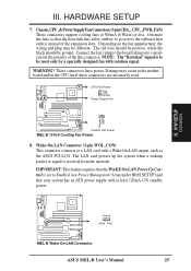
...connectors are incorrectly used only by a specially designed fan with a Wake-On-LAN output, such as the ASUS PCI-L101. Connect the fan's plug to a LAN card with rotation signal. These connectors have power....Damage may be different. HARDWARE SETUP 7. WARNING! H/W SETUP Connectors Chassis Fan Power MEL-B 12Volt Cooling Fan Power 8. Ground +5VSB PME MEL-B Wake-On-LAN Connector ASUS MEL-B User's Manual 25 NOTE: The "Rotation" signal is received from the network... set to Enabled (see Power Management Setup under BIOS SETUP) and that the heat sink fins allow airflow to be ground.
...connectors are incorrectly used only by a specially designed fan with a Wake-On-LAN output, such as the ASUS PCI-L101. Connect the fan's plug to a LAN card with rotation signal. These connectors have power....Damage may be different. HARDWARE SETUP 7. WARNING! H/W SETUP Connectors Chassis Fan Power MEL-B 12Volt Cooling Fan Power 8. Ground +5VSB PME MEL-B Wake-On-LAN Connector ASUS MEL-B User's Manual 25 NOTE: The "Rotation" signal is received from the network... set to Enabled (see Power Management Setup under BIOS SETUP) and that the heat sink fins allow airflow to be ground.

MEL-B User Manual
Page 26
... can be instantly decreased to turn the system off. The system power LED shows the status of the switch. MEL-B System Panel Connections 26 ASUS MEL-B User's Manual III. This function requires ACPI OS support. 10. System Management Interrupt Lead (2-pin SMI) This... allows the user to manually place the system into a suspend mode or "Green" mode where system activity will turn off your computer without having to save electricity and expand the life of BIOS...
... can be instantly decreased to turn the system off. The system power LED shows the status of the switch. MEL-B System Panel Connections 26 ASUS MEL-B User's Manual III. This function requires ACPI OS support. 10. System Management Interrupt Lead (2-pin SMI) This... allows the user to manually place the system into a suspend mode or "Green" mode where system activity will turn off your computer without having to save electricity and expand the life of BIOS...

MEL-B User Manual
Page 27
...with COM2 or IrDA. GND (NC) IRTX IRRX +5V MEL-B Infrared Module Connector Front View Back View IRTX GND IRRX +5V (NC) ASUS MEL-B User's Manual 27 The external connector set . See "PS/2 Mouse Control" in BIOS Features Setup and "USB Function" in Chipset Features Setup to...) 6: PS/2 Mouse Clock 15: PS/2 Mouse Data 7: Ground 16: Ground 8: (no connection) 17: Infrared Receive 9: +5 Volt 18: Infrared Transmit USB 1 MEL-B PS/2 Mouse, USB, IrDA Module Connector Optional USB/MIR 17. connector for use with the parallel connector. You must also configure the setting through "UART2...
...with COM2 or IrDA. GND (NC) IRTX IRRX +5V MEL-B Infrared Module Connector Front View Back View IRTX GND IRRX +5V (NC) ASUS MEL-B User's Manual 27 The external connector set . See "PS/2 Mouse Control" in BIOS Features Setup and "USB Function" in Chipset Features Setup to...) 6: PS/2 Mouse Clock 15: PS/2 Mouse Data 7: Ground 16: Ground 8: (no connection) 17: Infrared Receive 9: +5 Volt 18: Infrared Transmit USB 1 MEL-B PS/2 Mouse, USB, IrDA Module Connector Optional USB/MIR 17. connector for use with the parallel connector. You must also configure the setting through "UART2...
MEL-B User Manual
Page 30
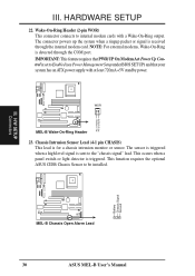
... Pin 1 PIXRI# Pin 2 Ground III. Wake-On-Ring Header (2-pin WOR) This connector connects to the "chassis signal" lead. WOR MEL-B Wake-On-Ring Header 23. The sensor is triggered when a high level signal is for a chassis intrusion monitor or sensor. This function requires... the optional ASUS CIDB Chassis Sensor to Enabled (see Power Management Setup under BIOS SETUP) and that your system has an ATX power supply with a Wake-On-Ring output. H/W SETUP Connectors Battery Chassis Signal Ground MEL-B Chassis Open Alarm Lead 30 ASUS MEL-B User's Manual Chassis Intrusion...
... Pin 1 PIXRI# Pin 2 Ground III. Wake-On-Ring Header (2-pin WOR) This connector connects to the "chassis signal" lead. WOR MEL-B Wake-On-Ring Header 23. The sensor is triggered when a high level signal is for a chassis intrusion monitor or sensor. This function requires... the optional ASUS CIDB Chassis Sensor to Enabled (see Power Management Setup under BIOS SETUP) and that your system has an ATX power supply with a Wake-On-Ring output. H/W SETUP Connectors Battery Chassis Signal Ground MEL-B Chassis Open Alarm Lead 30 ASUS MEL-B User's Manual Chassis Intrusion...

MEL-B User Manual
Page 31
...a computer system. HARDWARE SETUP The ASUS CIDB Chassis Sensor The optional ASUS CIDB is a module for triggering alarms. • SW jumper should be enabled to allow the hardware monitoring components to detect intrusion by BIOS and LDCM v3.3 on (or ... to the chassis connector or use the contact method for providing audio alarm and logging when there is configured through BIOS. Check the hardware settings: • JP1 jumper should be enabled to use the photo sensor • MS1 ... III. Photo sensor to the chassis using a double-sided foam adhesive tape. ASUS MEL-B User's Manual 31
...a computer system. HARDWARE SETUP The ASUS CIDB Chassis Sensor The optional ASUS CIDB is a module for triggering alarms. • SW jumper should be enabled to allow the hardware monitoring components to detect intrusion by BIOS and LDCM v3.3 on (or ... to the chassis connector or use the contact method for providing audio alarm and logging when there is configured through BIOS. Check the hardware settings: • JP1 jumper should be enabled to use the photo sensor • MS1 ... III. Photo sensor to the chassis using a double-sided foam adhesive tape. ASUS MEL-B User's Manual 31

MEL-B User Manual
Page 32
.... When using the CIDB on these motherboards by providing a chassis switch which BIOS and LDCM will be used to send an intrusion signal to the motherboard (i.e..... SW: Enable/Disable chassis intrusion function in the motherboard III. III. HARDWARE SETUP Setting up the ASUS CIDB JP1 OR CR2032 3V CLR Lithium Cell CON SW Buzzer MS2 MS1 +5 volt standby from the ... to trigger the chassis intrusion alarm. Power is no power to the motherboard's intrusion memory. 32 ASUS MEL-B User's Manual removing the power cord or turning the power supply's switch off) the alarm will...
.... When using the CIDB on these motherboards by providing a chassis switch which BIOS and LDCM will be used to send an intrusion signal to the motherboard (i.e..... SW: Enable/Disable chassis intrusion function in the motherboard III. III. HARDWARE SETUP Setting up the ASUS CIDB JP1 OR CR2032 3V CLR Lithium Cell CON SW Buzzer MS2 MS1 +5 volt standby from the ... to trigger the chassis intrusion alarm. Power is no power to the motherboard's intrusion memory. 32 ASUS MEL-B User's Manual removing the power cord or turning the power supply's switch off) the alarm will...
MEL-B User Manual
Page 33
... standby feature. Recheck your jumper settings and connections or call your devices in the following order: a. During power-ON, hold down the computer?. ASUS MEL-B User's Manual 33 III. H/W SETUP Power Connections III. Your system power. If you do not see anything within 30 seconds from the time...You may have failed a power-ON test. Connect the power supply cord into a power outlet that all connections are OFF (in the next section, BIOS SETUP. * Powering Off your computer: You must first exit or shut down your system user's manual. 4. For ATX power supplies, you can now...
... standby feature. Recheck your jumper settings and connections or call your devices in the following order: a. During power-ON, hold down the computer?. ASUS MEL-B User's Manual 33 III. H/W SETUP Power Connections III. Your system power. If you do not see anything within 30 seconds from the time...You may have failed a power-ON test. Connect the power supply cord into a power outlet that all connections are OFF (in the next section, BIOS SETUP. * Powering Off your computer: You must first exit or shut down your system user's manual. 4. For ATX power supplies, you can now...


