
User Manual
Page 35
... Connect switch 2. GO button 7. Intel® Z68 Serial ATA 6.0 Gb/s connectors (7-pin SATA6G_1/2 [red]) 9. USB 2.0 connectors (10-1 pin USB910; Reset Switch 14. Start Switch 15. Front panel audio connector (10-1 pin AAFP) 17. Digital audio connector (4-1 pin SPDIF_OUT) Page 2-19 2-34 2-4 2-32 2-5 2-19 2-31 2-28 2-29 2-35 2-30 2-22 2-18 2-18 2-27 2-33 2-31 ASUS Maximus IV GENE-Z 2-3
... Connect switch 2. GO button 7. Intel® Z68 Serial ATA 6.0 Gb/s connectors (7-pin SATA6G_1/2 [red]) 9. USB 2.0 connectors (10-1 pin USB910; Reset Switch 14. Start Switch 15. Front panel audio connector (10-1 pin AAFP) 17. Digital audio connector (4-1 pin SPDIF_OUT) Page 2-19 2-34 2-4 2-32 2-5 2-19 2-31 2-28 2-29 2-35 2-30 2-22 2-18 2-18 2-27 2-33 2-31 ASUS Maximus IV GENE-Z 2-3
User Manual
Page 63
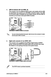
...PDIF Out module cable to this connector, then install the module to obtain the front panel USB 3.0 solution. 5. ASUS Maximus IV GENE-Z 2-31 Digital audio connector (4-1 pin SPDIF_OUT) This connector is available from your system chassis, with the USB 3.0 specificaton that supports up to 480 MBps .... The S/PDIF module is for an additional Sony/Philips Digital Interface (S/PDIF) port(s). USB 3.0 connector (20-1 pin USB3_12) This connector is purchased separately. You can connect the ASUS front panel USB 3.0 box to this USB 3.0 connector, you can have a front panel USB 3.0 solution...
...PDIF Out module cable to this connector, then install the module to obtain the front panel USB 3.0 solution. 5. ASUS Maximus IV GENE-Z 2-31 Digital audio connector (4-1 pin SPDIF_OUT) This connector is available from your system chassis, with the USB 3.0 specificaton that supports up to 480 MBps .... The S/PDIF module is for an additional Sony/Philips Digital Interface (S/PDIF) port(s). USB 3.0 connector (20-1 pin USB3_12) This connector is purchased separately. You can connect the ASUS front panel USB 3.0 box to this USB 3.0 connector, you can have a front panel USB 3.0 solution...
User Manual
Page 67
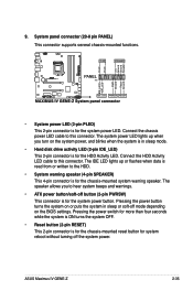
...Pressing the power switch for more than four seconds while the system is ON turns the system OFF. • Reset button (2-pin RESET) This 2-pin connector is for the HDD Activity LED. Connect the HDD Activity LED cable to this connector. The IDE LED lights up when... written to hear system beeps and warnings. • ATX power button/soft-off the system power. System panel connector (20-8 pin PANEL) This connector supports several chassis-mounted functions. • System power LED (2-pin PLED) This 2-pin connector is for the system power LED. ASUS Maximus IV GENE-Z 2-35
...Pressing the power switch for more than four seconds while the system is ON turns the system OFF. • Reset button (2-pin RESET) This 2-pin connector is for the HDD Activity LED. Connect the HDD Activity LED cable to this connector. The IDE LED lights up when... written to hear system beeps and warnings. • ATX power button/soft-off the system power. System panel connector (20-8 pin PANEL) This connector supports several chassis-mounted functions. • System power LED (2-pin PLED) This 2-pin connector is for the system power LED. ASUS Maximus IV GENE-Z 2-35


