User Manual
Page 11
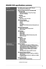
... on the next page) xi M5A99X EVO specifications summary IEEE 1394 ASUS unique features ASUS exclusive overclocking features VIA® 6308P controller supports 2 x IEEE 1394a ports (one at mid-board, one at 1MHz increment Overclocking Protection - Auto Tuning, TurboV, TPU switch ASUS Exclusive Features - ASUS Fan Xpert ASUS Q-Design - ASUS Q-DIMM - ASUS Q-Connector ASUS EZ DIY - ASUS O.C. ASUS EZ Flash 2 - Multi-language...
... on the next page) xi M5A99X EVO specifications summary IEEE 1394 ASUS unique features ASUS exclusive overclocking features VIA® 6308P controller supports 2 x IEEE 1394a ports (one at mid-board, one at 1MHz increment Overclocking Protection - Auto Tuning, TurboV, TPU switch ASUS Exclusive Features - ASUS Fan Xpert ASUS Q-Design - ASUS Q-DIMM - ASUS Q-Connector ASUS EZ DIY - ASUS O.C. ASUS EZ Flash 2 - Multi-language...
User Manual
Page 37
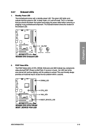
... illustration below shows the location of CPU, DRAM, VGA card, and HDD indicate key components status during POST (Power-on Self Test). POST State LEDs The POST State LEDs of the onboard LED. 2. This is solved. If an error is found , the LED next to the error device will continue lighting until the problem is... way to indicate that you should shut down the system and unplug the power cable before removing or plugging in soft‑off mode. Chapter 2 ASUS M5A99X EVO 2-19 The green LED lights up to locate the root problem within a second. Standby Power...
... illustration below shows the location of CPU, DRAM, VGA card, and HDD indicate key components status during POST (Power-on Self Test). POST State LEDs The POST State LEDs of the onboard LED. 2. This is solved. If an error is found , the LED next to the error device will continue lighting until the problem is... way to indicate that you should shut down the system and unplug the power cable before removing or plugging in soft‑off mode. Chapter 2 ASUS M5A99X EVO 2-19 The green LED lights up to locate the root problem within a second. Standby Power...
User Manual
Page 64
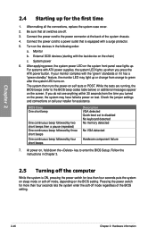
... up . System power 6. The system then runs the power-on , hold down the key to disabled No keyboard detected No memory detected No VGA detected Hardware component failure 7. Follow the instructions in the following order: a. Pressing the power switch for assistance. For systems with a surge protector.... 5. External SCSI devices (starting with the "green" standards or if it has a "power standby" feature, the monitor LED may have failed a power-on the screen. Turn on the devices in Chapter 3. 2.5 Turning off mode, depending on the chain) c. If ...
... up . System power 6. The system then runs the power-on , hold down the key to disabled No keyboard detected No memory detected No VGA detected Hardware component failure 7. Follow the instructions in the following order: a. Pressing the power switch for assistance. For systems with a surge protector.... 5. External SCSI devices (starting with the "green" standards or if it has a "power standby" feature, the monitor LED may have failed a power-on the screen. Turn on the devices in Chapter 3. 2.5 Turning off mode, depending on the chain) c. If ...


