
M5A97 LE R2.0 User's Manual
Page 1
Motherboard M5A97 LE R2.0
Motherboard M5A97 LE R2.0

M5A97 LE R2.0 User's Manual
Page 3
TPU (TurboV Processing Unit) & EPU (Energy Processing Unit 1-2 1.1.3 ASUS Exclusive Features 1-2 1.1.4 ASUS Quiet Thermal Solution 1-3 1.1.5 ASUS EZ DIY 1-3 1.1.6 Other special features 1-4 1.2 Motherboard overview 1-5 1.2.1 Before you proceed 1-5 1.2.2 Motherboard layout 1-6 1.2.3 Central ...2-16 2.5 Turning off the computer 2-16 iii Contents Safety information...vi About this guide...vii M5A97 LE R2.0 specifications summary ix Package contents...xii Installation tools and components xiii Product introduction 1.1 Special features 1-1 1.1.1 Product highlights 1-1 1.1.2 DIP...
TPU (TurboV Processing Unit) & EPU (Energy Processing Unit 1-2 1.1.3 ASUS Exclusive Features 1-2 1.1.4 ASUS Quiet Thermal Solution 1-3 1.1.5 ASUS EZ DIY 1-3 1.1.6 Other special features 1-4 1.2 Motherboard overview 1-5 1.2.1 Before you proceed 1-5 1.2.2 Motherboard layout 1-6 1.2.3 Central ...2-16 2.5 Turning off the computer 2-16 iii Contents Safety information...vi About this guide...vii M5A97 LE R2.0 specifications summary ix Package contents...xii Installation tools and components xiii Product introduction 1.1 Special features 1-1 1.1.1 Product highlights 1-1 1.1.2 DIP...

M5A97 LE R2.0 User's Manual
Page 9
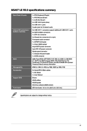
M5A97 LE R2.0 specifications summary CPU Chipset System Bus Memory Expansion slots Multi-GPU...CPU AMD® 970 / SB950 Up to DDR3 1066MHz. Optical S/PDIF out header at the back panel) (continued on the next page) ix ASUS Noise Filter 1 x Asmedia® USB3.0 controller: - 2 x USB 3.0/2.0 ports at back panel (blue) AMD® SB950 Chipset: - ... install a total memory of 3GB system memory if you are using a Windows® 32-bit operating system. • Refer to www.asus.com for the latest Memory QVL (Qualified Vendors List). 2 x PCIe 2.0 x16 slots (Blue @x16 speed, Black @x4 speed) 2...
M5A97 LE R2.0 specifications summary CPU Chipset System Bus Memory Expansion slots Multi-GPU...CPU AMD® 970 / SB950 Up to DDR3 1066MHz. Optical S/PDIF out header at the back panel) (continued on the next page) ix ASUS Noise Filter 1 x Asmedia® USB3.0 controller: - 2 x USB 3.0/2.0 ports at back panel (blue) AMD® SB950 Chipset: - ... install a total memory of 3GB system memory if you are using a Windows® 32-bit operating system. • Refer to www.asus.com for the latest Memory QVL (Qualified Vendors List). 2 x PCIe 2.0 x16 slots (Blue @x16 speed, Black @x4 speed) 2...

M5A97 LE R2.0 User's Manual
Page 10
... frequency tuning from 100MHz up to 600MHz at 1MHz increment Overclocking Protection: - ASUS Q-Slot Precision Tweaker 2 - EPU ASUS TPU - ASUS Network iControl - vDRAM Bus: Adjustable DRAM voltage at 0.00625V increment - M5A97 LE R2.0 specifications summary ASUS unique features ASUS exclusive overclocking features ASUS Dual Intelligent Processors ASUS Power Design - 4+2 Phase Power Design ASUS EPU - vNB: Adjustable NB voltage at 0.00625V increment -
... frequency tuning from 100MHz up to 600MHz at 1MHz increment Overclocking Protection: - ASUS Q-Slot Precision Tweaker 2 - EPU ASUS TPU - ASUS Network iControl - vDRAM Bus: Adjustable DRAM voltage at 0.00625V increment - M5A97 LE R2.0 specifications summary ASUS unique features ASUS exclusive overclocking features ASUS Dual Intelligent Processors ASUS Power Design - 4+2 Phase Power Design ASUS EPU - vNB: Adjustable NB voltage at 0.00625V increment -
M5A97 LE R2.0 User's Manual
Page 11
M5A97 LE R2.0 specifications summary Back Panel I/O ports Internal I/O connectors / buttons / switches BIOS Manageability Accessories Support DVD Form factor 1 x PS/2 Keyboard (Purple) 1 x PS/2 Mouse (Green) 1 x LAN (RJ-45) ... connector 1 x Chassis Intrusion header 1 x COM connector 64Mb Flash ROM, UEFI BIOS, PnP, DMI 2.0, WfM 2.0, SM BIOS 2.7, ACPI 2.0a Multi-language BIOS, ASUS EZ Flash 2, F12 PrintScreen, F3 Shortcut Function and ASUS DRAM SPD (Serieal Presence Detect) memory information WfM 2.0, DMI 2.0, WOL by PME, WOR by PME, PXE 2 x Serial ATA 6.0Gb/s cables 1 x I/O Shield...
M5A97 LE R2.0 specifications summary Back Panel I/O ports Internal I/O connectors / buttons / switches BIOS Manageability Accessories Support DVD Form factor 1 x PS/2 Keyboard (Purple) 1 x PS/2 Mouse (Green) 1 x LAN (RJ-45) ... connector 1 x Chassis Intrusion header 1 x COM connector 64Mb Flash ROM, UEFI BIOS, PnP, DMI 2.0, WfM 2.0, SM BIOS 2.7, ACPI 2.0a Multi-language BIOS, ASUS EZ Flash 2, F12 PrintScreen, F3 Shortcut Function and ASUS DRAM SPD (Serieal Presence Detect) memory information WfM 2.0, DMI 2.0, WOL by PME, WOR by PME, PXE 2 x Serial ATA 6.0Gb/s cables 1 x I/O Shield...

M5A97 LE R2.0 User's Manual
Page 12
Actual product specifications may vary with different models. xii Package contents Check your motherboard package for the following items. M5A97 LE R2.0 ASUS M5A97 LE R2.0 motherboard SOCKET AM3+ User Manual User Guide Support DVD 2 x Serial ATA 6.0 Gb/s cables 1 x ASUS I/O Shield • If any of the above items is damaged or missing, contact your retailer. • The illustrated items above are for reference only.
Actual product specifications may vary with different models. xii Package contents Check your motherboard package for the following items. M5A97 LE R2.0 ASUS M5A97 LE R2.0 motherboard SOCKET AM3+ User Manual User Guide Support DVD 2 x Serial ATA 6.0 Gb/s cables 1 x ASUS I/O Shield • If any of the above items is damaged or missing, contact your retailer. • The illustrated items above are for reference only.

M5A97 LE R2.0 User's Manual
Page 15
... to provide excellent system performance and overclocking capabilities. Native SATA 6.0 Gb/s support With AMD® SB950 chipset natively support for a cool and quiet operating environment. M5A97 LE R2.0 1-1 This motherboard also supports AMD® CPUs in the new 32nm manufacturing process. True USB 3.0 Support Experience ultra-fast data transfers at 5.0 Gbps with rendering...
... to provide excellent system performance and overclocking capabilities. Native SATA 6.0 Gb/s support With AMD® SB950 chipset natively support for a cool and quiet operating environment. M5A97 LE R2.0 1-1 This motherboard also supports AMD® CPUs in the new 32nm manufacturing process. True USB 3.0 Support Experience ultra-fast data transfers at 5.0 Gbps with rendering...

M5A97 LE R2.0 User's Manual
Page 17
... you with more flexibility, convenience, and easy to navigate UEFI BIOS than 2.2 TB. ASUS EZ-Flash 2 ASUS EZ Flash 2 is ASUS unique fast-charging software that goes beyond the traditional keyboard-only BIOS controls, providing you a noiseless PC environment. Chapter 1 M5A97 LE R2.0 1-3 With its easy and user-friendly interface, you can easily charge iPod, iPhone...
... you with more flexibility, convenience, and easy to navigate UEFI BIOS than 2.2 TB. ASUS EZ-Flash 2 ASUS EZ Flash 2 is ASUS unique fast-charging software that goes beyond the traditional keyboard-only BIOS controls, providing you a noiseless PC environment. Chapter 1 M5A97 LE R2.0 1-3 With its easy and user-friendly interface, you can easily charge iPod, iPhone...

M5A97 LE R2.0 User's Manual
Page 19
... the power supply case, to avoid damaging them due to static electricity. • Hold components by the edges to the motherboard, peripherals, or components. Chapter 1 M5A97 LE R2.0 1-5
... the power supply case, to avoid damaging them due to static electricity. • Hold components by the edges to the motherboard, peripherals, or components. Chapter 1 M5A97 LE R2.0 1-5

M5A97 LE R2.0 User's Manual
Page 20
... USB34 2 LAN_USB12 CHA_FAN1 AUDIO AMD® 970 30.5cm(12.0in) RTL 8111F Super I/O TPU ALC 887 PCIEX16_1 PCIEX1_1 Lithium Cell CMOS Power PCIEX1_2 64Mb M5A97 LE R2.0 BIOS PCIEX16_2 SATA6G_6 AMD® SATA6G_5 5 SB950 6 PCI1 7 SATA6G_2 SATA6G_4 SB_PWR PCI2 COM1 SPDIF_OUT AAFP USB1314 USB1112 USB910 CLRTC PANEL SATA6G_1 SATA6G_3 5 CHASSIS 13 12...
... USB34 2 LAN_USB12 CHA_FAN1 AUDIO AMD® 970 30.5cm(12.0in) RTL 8111F Super I/O TPU ALC 887 PCIEX16_1 PCIEX1_1 Lithium Cell CMOS Power PCIEX1_2 64Mb M5A97 LE R2.0 BIOS PCIEX16_2 SATA6G_6 AMD® SATA6G_5 5 SB950 6 PCI1 7 SATA6G_2 SATA6G_4 SB_PWR PCI2 COM1 SPDIF_OUT AAFP USB1314 USB1112 USB910 CLRTC PANEL SATA6G_1 SATA6G_3 5 CHASSIS 13 12...
M5A97 LE R2.0 User's Manual
Page 21
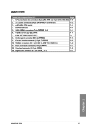
... 11. Serial port connector (10-1 pin COM1) 1-23 13. Clear RTC RAM (3-pin CLRTC) 1-17 8. DDR3 DIMM slots 1-9 5. Digital audio connector (4-1 pin SPDIF_OUT) 1-21 Chapter 1 M5A97 LE R2.0 1-7 Layout contents Connectors/Jumpers/Slots/LED Page 1. System panel connector (20-8 pin PANEL) 1-24 9. Front panel audio connector (10-1 pin AAFP) 1-21 12. AMD AM3...
... 11. Serial port connector (10-1 pin COM1) 1-23 13. Clear RTC RAM (3-pin CLRTC) 1-17 8. DDR3 DIMM slots 1-9 5. Digital audio connector (4-1 pin SPDIF_OUT) 1-21 Chapter 1 M5A97 LE R2.0 1-7 Layout contents Connectors/Jumpers/Slots/LED Page 1. System panel connector (20-8 pin PANEL) 1-24 9. Front panel audio connector (10-1 pin AAFP) 1-21 12. AMD AM3...

M5A97 LE R2.0 User's Manual
Page 22
M5A97 LE R2.0 M5A97 LE R2.0 CPU socket AM3+ Ensure that you use a CPU designed for the AM3+ socket. DO NOT force the CPU into the socket to prevent bending the ...
M5A97 LE R2.0 M5A97 LE R2.0 CPU socket AM3+ Ensure that you use a CPU designed for the AM3+ socket. DO NOT force the CPU into the socket to prevent bending the ...
M5A97 LE R2.0 User's Manual
Page 23
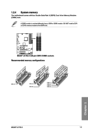
DIMM_A1 DIMM_A2 DIMM_B1 DIMM_B2 1.2.4 System memory The motherboard comes with four Double Data Rate 3 (DDR3) Dual Inline Memory Modules (DIMM) slots. DO NOT install a DDR or DDR2 memory module to the DDR3 slot. M5A97 LE R2.0 M5A97 LE R2.0 240-pin DDR3 DIMM sockets Recommended memory configurations Chapter 1 M5A97 LE R2.0 1-9 A DDR3 module is notched differently from a DDR or DDR2 module.
DIMM_A1 DIMM_A2 DIMM_B1 DIMM_B2 1.2.4 System memory The motherboard comes with four Double Data Rate 3 (DDR3) Dual Inline Memory Modules (DIMM) slots. DO NOT install a DDR or DDR2 memory module to the DDR3 slot. M5A97 LE R2.0 M5A97 LE R2.0 240-pin DDR3 DIMM sockets Recommended memory configurations Chapter 1 M5A97 LE R2.0 1-9 A DDR3 module is notched differently from a DDR or DDR2 module.
M5A97 LE R2.0 User's Manual
Page 29
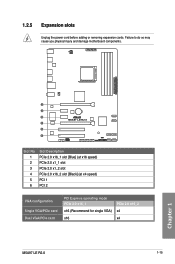
Failure to do so may cause you physical injury and damage motherboard components. SOCKET AM3+ 1 2 3 M5A97 LE R2.0 4 5 6 Slot No. 1 2 3 4 5 6 Slot Description PCIe 2.0 x16_1 slot [Blue] (at x16 speed) PCIe 2.0 x1_1 slot PCIe 2.0 x1_2 slot PCIe 2.0 x16_2 slot [Black] (at x4 speed) PCI 1 PCI 2 VGA configuration Single VGA/PCIe card Dual VGA/PCIe card PCI Express operating mode PCIe 2.0 x16_1 x16 (Recommend for single VGA) x16 PCIe 2.0 x16_2 x4 x4 M5A97 LE R2.0 1-15 Chapter 1 1.2.5 Expansion slots Unplug the power cord before adding or removing expansion cards.
Failure to do so may cause you physical injury and damage motherboard components. SOCKET AM3+ 1 2 3 M5A97 LE R2.0 4 5 6 Slot No. 1 2 3 4 5 6 Slot Description PCIe 2.0 x16_1 slot [Blue] (at x16 speed) PCIe 2.0 x1_1 slot PCIe 2.0 x1_2 slot PCIe 2.0 x16_2 slot [Black] (at x4 speed) PCI 1 PCI 2 VGA configuration Single VGA/PCIe card Dual VGA/PCIe card PCI Express operating mode PCIe 2.0 x16_1 x16 (Recommend for single VGA) x16 PCIe 2.0 x16_2 x4 x4 M5A97 LE R2.0 1-15 Chapter 1 1.2.5 Expansion slots Unplug the power cord before adding or removing expansion cards.
M5A97 LE R2.0 User's Manual
Page 31
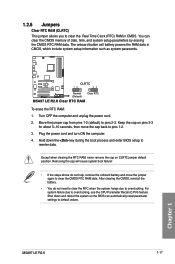
... the battery. • You do not help, remove the onboard battery and move the cap back to clear the CMOS RTC RAM data. Chapter 1 M5A97 LE R2.0 1-17 1.2.6 Jumpers Clear RTC RAM (CLRTC) This jumper allows you to overclocking. The onboard button cell battery powers the RAM data in CMOS. Move... setup parameters by erasing the CMOS RTC RAM data. Shut down the key during the boot process and enter BIOS setup to pins 2-3. M5A97 LE R2.0 CLRTC 12 23 Normal (Default) Clear RTC M5A97 LE R2.0 Clear RTC RAM To erase the RTC RAM: 1. For system failure due to default values.
... the battery. • You do not help, remove the onboard battery and move the cap back to clear the CMOS RTC RAM data. Chapter 1 M5A97 LE R2.0 1-17 1.2.6 Jumpers Clear RTC RAM (CLRTC) This jumper allows you to overclocking. The onboard button cell battery powers the RAM data in CMOS. Move... setup parameters by erasing the CMOS RTC RAM data. Shut down the key during the boot process and enter BIOS setup to pins 2-3. M5A97 LE R2.0 CLRTC 12 23 Normal (Default) Clear RTC M5A97 LE R2.0 Clear RTC RAM To erase the RTC RAM: 1. For system failure due to default values.

M5A97 LE R2.0 User's Manual
Page 32
1.2.7 Onboard LEDs Standby Power LED The motherboard comes with a standby power LED that lights up to indicate that you should shut down the system and unplug the power cable before removing or plugging in soft-off mode. This is a reminder that the system is ON, in sleep mode, or in any motherboard component. SB_PWR M5A97 LE R2.0 ON OFF Standby Power Powered Off M5A97 LE R2.0 Onboard LED Chapter 1 1-18 Chapter 1: Product introduction The illustration below shows the location of the onboard LED.
1.2.7 Onboard LEDs Standby Power LED The motherboard comes with a standby power LED that lights up to indicate that you should shut down the system and unplug the power cable before removing or plugging in soft-off mode. This is a reminder that the system is ON, in sleep mode, or in any motherboard component. SB_PWR M5A97 LE R2.0 ON OFF Standby Power Powered Off M5A97 LE R2.0 Onboard LED Chapter 1 1-18 Chapter 1: Product introduction The illustration below shows the location of the onboard LED.

M5A97 LE R2.0 User's Manual
Page 33
...can create a RAID 0, RAID 1, RAID 5, RAID 10, or JBOD configuration through the onboard controller. Chapter 1 M5A97 LE R2.0 1-19 SATA6G_6 GND RSATA_TXP6 RSATA_TXN6 GND RSATA_RXN6 RSATA_RXP6 GND SATA6G_5 GND RSATA_TXP5 RSATA_TXN5 GND RSATA_RXN5 RSATA_RXP5 GND SATA6G_2 SATA6G_4 GND ... RSATA_RXN2 GND RSATA_TXN2 RSATA_TXP2 GND GND RSATA_TXP3 RSATA_TXN3 GND RSATA_RXN3 RSATA_RXP3 GND GND RSATA_TXP1 RSATA_TXN1 GND RSATA_RXN1 RSATA_RXP1 GND M5A97 LE R2.0 SATA6G_1 SATA6G_3 M5A97 LE R2.0 SATA 6.0Gb/s connectors • These connectors are for the Serial ATA 6.0 Gb/s signal cables for ...
...can create a RAID 0, RAID 1, RAID 5, RAID 10, or JBOD configuration through the onboard controller. Chapter 1 M5A97 LE R2.0 1-19 SATA6G_6 GND RSATA_TXP6 RSATA_TXN6 GND RSATA_RXN6 RSATA_RXP6 GND SATA6G_5 GND RSATA_TXP5 RSATA_TXN5 GND RSATA_RXN5 RSATA_RXP5 GND SATA6G_2 SATA6G_4 GND ... RSATA_RXN2 GND RSATA_TXN2 RSATA_TXP2 GND GND RSATA_TXP3 RSATA_TXN3 GND RSATA_RXN3 RSATA_RXP3 GND GND RSATA_TXP1 RSATA_TXN1 GND RSATA_RXN1 RSATA_RXP1 GND M5A97 LE R2.0 SATA6G_1 SATA6G_3 M5A97 LE R2.0 SATA 6.0Gb/s connectors • These connectors are for the Serial ATA 6.0 Gb/s signal cables for ...
M5A97 LE R2.0 User's Manual
Page 34
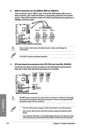
... FAN IN CPU FAN PWR GND CHA FAN PWM CHA FAN IN CHA FAN PWR GND Chapter 1 M5A97 LE R2.0 CHA_FAN1 GND CHA FAN PWR CHA FAN IN CHA FAN PWM M5A97 LE R2.0 Fan connectors DO NOT forget to connect the fan cables to 480Mbps connection speed. These USB connectors ...comply with USB 2.0 specification that you plug the rear chassis fan cable to a slot opening at the back of maximum 1A (12 W) fan power. • Only the CPU_FAN and CHA_FAN1/2/3 connectors support the ASUS...
... FAN IN CPU FAN PWR GND CHA FAN PWM CHA FAN IN CHA FAN PWR GND Chapter 1 M5A97 LE R2.0 CHA_FAN1 GND CHA FAN PWR CHA FAN IN CHA FAN PWM M5A97 LE R2.0 Fan connectors DO NOT forget to connect the fan cables to 480Mbps connection speed. These USB connectors ...comply with USB 2.0 specification that you plug the rear chassis fan cable to a slot opening at the back of maximum 1A (12 W) fan power. • Only the CPU_FAN and CHA_FAN1/2/3 connectors support the ASUS...

M5A97 LE R2.0 User's Manual
Page 35
...PIN 1 MIC2 MICPWR Line out_R NC Line out_L PORT1 L PORT1 R PORT2 R SENSE_SEND PORT2 L M5A97 LE R2.0 HD-audio-compliant Legacy AC'97 pin definition compliant definition M5A97 LE R2.0 Front panel audio connector • We recommend that the audio device of Sound playback is Realtek...audio connector (4-1 pin SPDIF_OUT) This connector is for an additional Sony/Philips Digital Interface (S/PDIF) port. +5V SPDIFOUT GND M5A97 LE R2.0 SPDIF_OUT M5A97 LE R2.0 Digital audio connector Ensure that you connect a high-definition front panel audio module to this connector to avail of the front...
...PIN 1 MIC2 MICPWR Line out_R NC Line out_L PORT1 L PORT1 R PORT2 R SENSE_SEND PORT2 L M5A97 LE R2.0 HD-audio-compliant Legacy AC'97 pin definition compliant definition M5A97 LE R2.0 Front panel audio connector • We recommend that the audio device of Sound playback is Realtek...audio connector (4-1 pin SPDIF_OUT) This connector is for an additional Sony/Philips Digital Interface (S/PDIF) port. +5V SPDIFOUT GND M5A97 LE R2.0 SPDIF_OUT M5A97 LE R2.0 Digital audio connector Ensure that you connect a high-definition front panel audio module to this connector to avail of the front...

M5A97 LE R2.0 User's Manual
Page 36
... GND +3 Volts +12 Volts +12 Volts +5V Standby Power OK GND PIN 1 +5 Volts GND +5 Volts GND +3 Volts +3 Volts PIN 1 M5A97 LE R2.0 ATX power connectors GND +5 Volts +5 Volts +5 Volts -5 Volts GND GND GND PSON# GND -12 Volts +3 Volts • For a fully configured system, we recommend that... supply requirement for details. • If you use a PSU with 1000W power or above to the Recommended Power Supply Wattage Calculator at http://support.asus. The system may become unstable or may not boot up if the power is inadequate. • If you use a PSU with higher power output...
... GND +3 Volts +12 Volts +12 Volts +5V Standby Power OK GND PIN 1 +5 Volts GND +5 Volts GND +3 Volts +3 Volts PIN 1 M5A97 LE R2.0 ATX power connectors GND +5 Volts +5 Volts +5 Volts -5 Volts GND GND GND PSON# GND -12 Volts +3 Volts • For a fully configured system, we recommend that... supply requirement for details. • If you use a PSU with 1000W power or above to the Recommended Power Supply Wattage Calculator at http://support.asus. The system may become unstable or may not boot up if the power is inadequate. • If you use a PSU with higher power output...


