User Manual
Page 3
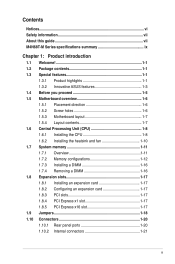
Contents Notices...vi Safety information vii About this guide vii M4N68T-M Series specifications summary ix Chapter 1: Product introduction 1.1 Welcome 1-1 1.2 Package contents 1-1 1.3 Special features 1-1 1.3.1 Product highlights 1-1 1.3.2 Innovative ASUS features 1-3 1.4 Before you proceed 1-5 1.5 Motherboard overview 1-6 1.5.1 Placement direction 1-6 1.5.2 Screw holes 1-6 1.5.3 Motherboard layout 1-7 1.5.4 Layout contents 1-7 1.6 Central Processing Unit (CPU 1-8 1.6.1 Installing the CPU 1-8 1.6.2 Installing the heatsink and fan 1-10 1.7 System...
Contents Notices...vi Safety information vii About this guide vii M4N68T-M Series specifications summary ix Chapter 1: Product introduction 1.1 Welcome 1-1 1.2 Package contents 1-1 1.3 Special features 1-1 1.3.1 Product highlights 1-1 1.3.2 Innovative ASUS features 1-3 1.4 Before you proceed 1-5 1.5 Motherboard overview 1-6 1.5.1 Placement direction 1-6 1.5.2 Screw holes 1-6 1.5.3 Motherboard layout 1-7 1.5.4 Layout contents 1-7 1.6 Central Processing Unit (CPU 1-8 1.6.1 Installing the CPU 1-8 1.6.2 Installing the heatsink and fan 1-10 1.7 System...
User Manual
Page 6
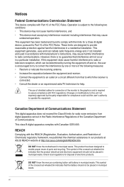
.... REACH Complying with FCC regulations. DO NOT throw the mercury-containing button cell battery in our products at ASUS REACH website at http://csr.asus.com/english/REACH.htm. These limits are designed to assure compliance with the REACH (Registration, Evaluation, Authorisation,...interference to Part 15 of shielded cables for a Class B digital device, pursuant to radio communications. vi DO NOT throw the motherboard in the Radio Interference Regulations of the Canadian Department of the following two conditions: • This device may cause undesired operation...
.... REACH Complying with FCC regulations. DO NOT throw the mercury-containing button cell battery in our products at ASUS REACH website at http://csr.asus.com/english/REACH.htm. These limits are designed to assure compliance with the REACH (Registration, Evaluation, Authorisation,...interference to Part 15 of shielded cables for a Class B digital device, pursuant to radio communications. vi DO NOT throw the motherboard in the Radio Interference Regulations of the Canadian Department of the following two conditions: • This device may cause undesired operation...

User Manual
Page 7
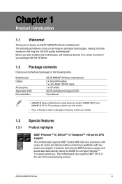
...staples away from connectors, slots, sockets and circuitry. • Avoid dust, humidity, and temperature extremes. Detailed descriptions of the motherboard and the new technology it , carefully read all cables are correctly connected and the power cables are using the product, ensure ... Chapter 1: Product introduction This chapter describes the features of the BIOS parameters are also provided. Operation safety • Before installing the motherboard and adding devices on a stable surface. • If you encounter technical problems with the package. • Before using , contact ...
...staples away from connectors, slots, sockets and circuitry. • Avoid dust, humidity, and temperature extremes. Detailed descriptions of the motherboard and the new technology it , carefully read all cables are correctly connected and the power cables are using the product, ensure ... Chapter 1: Product introduction This chapter describes the features of the BIOS parameters are also provided. Operation safety • Before installing the motherboard and adding devices on a stable surface. • If you encounter technical problems with the package. • Before using , contact ...
User Manual
Page 11
... line of ASUS quality motherboards! This motherboard also supports AMD® CPUs in your motherboard package for buying an ASUS® M4N68T-M Series motherboard! Before you for the following items. Motherboard Cables Accessories Application DVD Documentation ASUS M4N68T-M Series motherboard 2 x Serial ATA cables 1 x Ultra DMA 133/100 cable 1 x I/O shield ASUS motherboard Support DVD User Manual • M4N68T-M Series motherboards include these two models: M4N68T-M V2 and M4N68T-M LE V2. ASUS M4N68T-M Series...
... line of ASUS quality motherboards! This motherboard also supports AMD® CPUs in your motherboard package for buying an ASUS® M4N68T-M Series motherboard! Before you for the following items. Motherboard Cables Accessories Application DVD Documentation ASUS M4N68T-M Series motherboard 2 x Serial ATA cables 1 x Ultra DMA 133/100 cable 1 x I/O shield ASUS motherboard Support DVD User Manual • M4N68T-M Series motherboards include these two models: M4N68T-M V2 and M4N68T-M LE V2. ASUS M4N68T-M Series...
User Manual
Page 12
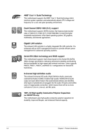
... 1800 (O.C.)/1600 (O.C.)/1333/1066 MHz to provide efficient power management for advanced operating systems. Serial ATA 3Gb/s technology and RAID support This motherboard supports hard drives based on M4N68T-M only) This motherboard uses high-quality conductive polymer capacitors for durability, improved lifespan, and enhanced thermal capacity. 1-2 Chapter 1: Product introduction Dual-Channel DDR3 1800...
... 1800 (O.C.)/1600 (O.C.)/1333/1066 MHz to provide efficient power management for advanced operating systems. Serial ATA 3Gb/s technology and RAID support This motherboard supports hard drives based on M4N68T-M only) This motherboard uses high-quality conductive polymer capacitors for durability, improved lifespan, and enhanced thermal capacity. 1-2 Chapter 1: Product introduction Dual-Channel DDR3 1800...
User Manual
Page 13
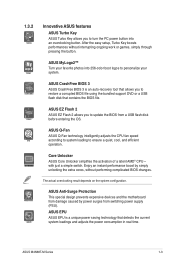
...intelligently adjusts the CPU fan speed according to system loading to personalize your system. with just a simple switch. ASUS M4N68T-M Series 1-3 After the easy setup, Turbo Key boosts performances without performing complicated BIOS changes. Enjoy an instant ...or games, simply through pressing the button. ASUS Anti-Surge Protection This special design prevents expensive devices and the motherboard from switching power supply (PSU). ASUS MyLogo2™ Turn your favorite photos into an overclocking button. ASUS CrashFree BIOS 3 ASUS CrashFree BIOS 3 is a unique power saving ...
...intelligently adjusts the CPU fan speed according to system loading to personalize your system. with just a simple switch. ASUS M4N68T-M Series 1-3 After the easy setup, Turbo Key boosts performances without performing complicated BIOS changes. Enjoy an instant ...or games, simply through pressing the button. ASUS Anti-Surge Protection This special design prevents expensive devices and the motherboard from switching power supply (PSU). ASUS MyLogo2™ Turn your favorite photos into an overclocking button. ASUS CrashFree BIOS 3 ASUS CrashFree BIOS 3 is a unique power saving ...

User Manual
Page 14
... reboot the system, and the BIOS automatically restores the CPU parameters to open the system chassis and clear the RTC data. Green ASUS This motherboard and its packaging comply with the ASUS vision of Hazardous Substances (RoHS). eliminates the need to their default settings. feature automatically restores the CPU default settings when the...
... reboot the system, and the BIOS automatically restores the CPU parameters to open the system chassis and clear the RTC data. Green ASUS This motherboard and its packaging comply with the ASUS vision of Hazardous Substances (RoHS). eliminates the need to their default settings. feature automatically restores the CPU default settings when the...
User Manual
Page 15
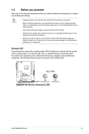
...The motherboard comes with a standby power LED that lights up to indicate that the system is a reminder that came with the component. • Before you install or remove any component, switch off mode. SB_PWR M4N68T-M V2 ON OFF Standby Power Powered Off M4N68T-M Series Onboard LED ASUS M4N68T-M Series... below shows the location of the following precautions before you install motherboard components or change any motherboard settings. • Unplug the power cord from the wall socket before removing or plugging in any motherboard component. This is ON, in sleep mode, or in the...
...The motherboard comes with a standby power LED that lights up to indicate that the system is a reminder that came with the component. • Before you install or remove any component, switch off mode. SB_PWR M4N68T-M V2 ON OFF Standby Power Powered Off M4N68T-M Series Onboard LED ASUS M4N68T-M Series... below shows the location of the following precautions before you install motherboard components or change any motherboard settings. • Unplug the power cord from the wall socket before removing or plugging in any motherboard component. This is ON, in sleep mode, or in the...
User Manual
Page 16
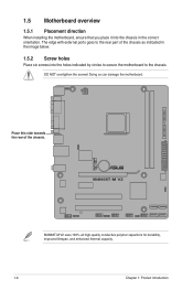
Doing so can damage the motherboard. M4N68T-M V2 M4N68T-M V2 uses 100% all high-quality conductive polymer capacitors for durability, improved lifespan, and enhanced thermal capacity. 1-6 Chapter 1: Product introduction Place this side towards the ... six screws into the chassis in the correct orientation. DO NOT overtighten the screws! 1.5 Motherboard overview 1.5.1 Placement direction When installing the motherboard, ensure that you place it into the holes indicated by circles to secure the motherboard to the chassis. The edge with external ports goes to the rear part of the...
Doing so can damage the motherboard. M4N68T-M V2 M4N68T-M V2 uses 100% all high-quality conductive polymer capacitors for durability, improved lifespan, and enhanced thermal capacity. 1-6 Chapter 1: Product introduction Place this side towards the ... six screws into the chassis in the correct orientation. DO NOT overtighten the screws! 1.5 Motherboard overview 1.5.1 Placement direction When installing the motherboard, ensure that you place it into the holes indicated by circles to secure the motherboard to the chassis. The edge with external ports goes to the rear part of the...
User Manual
Page 17
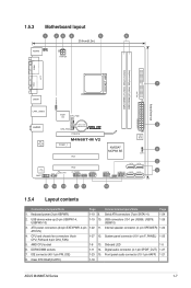
... 1-25 5. Digital audio connector (4-1 pin SPDIF_OUT) 1-27 7. Clear RTC RAM (CLRTC) 1-18 ASUS M4N68T-M Series 1-7 DDR3 DIMM sockets 1-11 14. USB device wake-up (3-pin USBPW1-4, USBPW5-10)... Serial ATA connectors (7-pin SATA1-4) 1-24 2. Internal speaker connector (4- AMD CPU socket 1-8 13. 1.5.3 Motherboard layout 1 23 4 5 6 20.8cm(8.2in) KB/MS KBPWR ATX12V COM1 DDR3 DIMM_A1 (64bit, 240...I/O CPU_FAN EATXPWR Lithium Cell 3 AUDIO CMOS Power CHA_FAN RTL 8211CL -VB PCIEX16 M4N68T-M V2 PCIEX1_1 PCI1 NVIDIA® MCP68 SE 8Mb BIOS 8 CLRTC 2 SATA2 SATA4 PCI2...
... 1-25 5. Digital audio connector (4-1 pin SPDIF_OUT) 1-27 7. Clear RTC RAM (CLRTC) 1-18 ASUS M4N68T-M Series 1-7 DDR3 DIMM sockets 1-11 14. USB device wake-up (3-pin USBPW1-4, USBPW5-10)... Serial ATA connectors (7-pin SATA1-4) 1-24 2. Internal speaker connector (4- AMD CPU socket 1-8 13. 1.5.3 Motherboard layout 1 23 4 5 6 20.8cm(8.2in) KB/MS KBPWR ATX12V COM1 DDR3 DIMM_A1 (64bit, 240...I/O CPU_FAN EATXPWR Lithium Cell 3 AUDIO CMOS Power CHA_FAN RTL 8211CL -VB PCIEX16 M4N68T-M V2 PCIEX1_1 PCI1 NVIDIA® MCP68 SE 8Mb BIOS 8 CLRTC 2 SATA2 SATA4 PCI2...
User Manual
Page 18
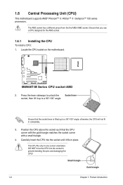
... 1-8 Chapter 1: Product introduction Locate the CPU socket on the motherboard. The AM3 socket has a different pinout from the the AM2+/AM2 socket. 1.6 Central Processing Unit (CPU) This motherboard supports AMD® Phenom™ II / Athlon™ II / Sempron™ 100 series processors. M4N68T-M V2 M4N68T-M Series CPU socket AM3 2. Ensure that the socket lever is...
... 1-8 Chapter 1: Product introduction Locate the CPU socket on the motherboard. The AM3 socket has a different pinout from the the AM2+/AM2 socket. 1.6 Central Processing Unit (CPU) This motherboard supports AMD® Phenom™ II / Athlon™ II / Sempron™ 100 series processors. M4N68T-M V2 M4N68T-M Series CPU socket AM3 2. Ensure that the socket lever is...
User Manual
Page 19
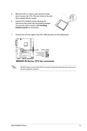
5. ASUS M4N68T-M Series 1-9 Install a CPU heatsink and fan following the instructions that it is in place, push down the socket lever to indicate that comes with the ... fail to section 1.6.2 Installing heatsink and fan for instructions. 7. The lever clicks on the motherboard. Connect the CPU fan cable to connect the CPU fan connector! M4N68T-M V2 CPU_FAN CPU FAN PWM CPU FAN IN CPU FAN PWR GND M4N68T-M Series CPU fan connector DO NOT forget to the CPU_FAN connector on the side...
5. ASUS M4N68T-M Series 1-9 Install a CPU heatsink and fan following the instructions that it is in place, push down the socket lever to indicate that comes with the ... fail to section 1.6.2 Installing heatsink and fan for instructions. 7. The lever clicks on the motherboard. Connect the CPU fan cable to connect the CPU fan connector! M4N68T-M V2 CPU_FAN CPU FAN PWM CPU FAN IN CPU FAN PWR GND M4N68T-M Series CPU fan connector DO NOT forget to the CPU_FAN connector on the side...

User Manual
Page 20
.... • If you purchased a separate CPU heatsink and fan assembly, ensure that a Thermal Interface Material is already installed on the motherboard upon purchase. • You do not match the CPU documentation, follow the latter. 2. Attach one end of the installed CPU, ensuring that the heatsink fits ...
.... • If you purchased a separate CPU heatsink and fan assembly, ensure that a Thermal Interface Material is already installed on the motherboard upon purchase. • You do not match the CPU documentation, follow the latter. 2. Attach one end of the installed CPU, ensuring that the heatsink fits ...
User Manual
Page 21
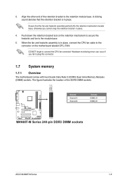
... memory 1.7.1 Overview The motherboard comes with two Double Data Rate 3 (DDR3) Dual Inline Memory Modules (DIMM) sockets. DO NOT forget to the retention module base. Align the other end of the DDR3 DIMM sockets: DIMM_A1 DIMM_B1 M4N68T-M V2 Channel Channel A Channel B Sockets DIMM_A1 DIMM_B1 M4N68T-M Series 240-pin DDR3 DIMM sockets ASUS M4N68T-M Series 1-11 When...
... memory 1.7.1 Overview The motherboard comes with two Double Data Rate 3 (DDR3) Dual Inline Memory Modules (DIMM) sockets. DO NOT forget to the retention module base. Align the other end of the DDR3 DIMM sockets: DIMM_A1 DIMM_B1 M4N68T-M V2 Channel Channel A Channel B Sockets DIMM_A1 DIMM_B1 M4N68T-M Series 240-pin DDR3 DIMM sockets ASUS M4N68T-M Series 1-11 When...

User Manual
Page 22
... you obtain memory modules from the higher-sized channel is then mapped for the OS can be about 3GB or less. M4N68T-M Series Motherboard Qualified Vendors Lists (QVL) DDR3-1800(O.C.)MHz capability Vendor Part No. AD31600X002GMU CM3X1G1600C9DHX CM3X2G1600C9DHX TR3X6G1600C8 G(XMP) TR3X6G1600C8D G(XMP) ...8226; DS N/A Heat-Sink Package 8-8-8-24 •• DS N/A Heat-Sink Package 8-8-8-24 •• continued on the motherboard. • This motherboard does not support DIMMs made up of memory, we recommend that you install 4GB or more memory on the next page 1-12...
... you obtain memory modules from the higher-sized channel is then mapped for the OS can be about 3GB or less. M4N68T-M Series Motherboard Qualified Vendors Lists (QVL) DDR3-1800(O.C.)MHz capability Vendor Part No. AD31600X002GMU CM3X1G1600C9DHX CM3X2G1600C9DHX TR3X6G1600C8 G(XMP) TR3X6G1600C8D G(XMP) ...8226; DS N/A Heat-Sink Package 8-8-8-24 •• DS N/A Heat-Sink Package 8-8-8-24 •• continued on the motherboard. • This motherboard does not support DIMMs made up of memory, we recommend that you install 4GB or more memory on the next page 1-12...

User Manual
Page 26
... socket. 1-16 Chapter 1: Product introduction Failure to do so can cause severe damage to unlock a DIMM socket. 2. Press the retaining clips outward to both the motherboard and the components. 1. Simultaneously press the retaining clips outward to avoid damaging the DIMM. 3. 1.7.3 Installing a DIMM Unplug the power supply before adding or removing DIMMs...
... socket. 1-16 Chapter 1: Product introduction Failure to do so can cause severe damage to unlock a DIMM socket. 2. Press the retaining clips outward to both the motherboard and the components. 1. Simultaneously press the retaining clips outward to avoid damaging the DIMM. 3. 1.7.3 Installing a DIMM Unplug the power supply before adding or removing DIMMs...
User Manual
Page 27
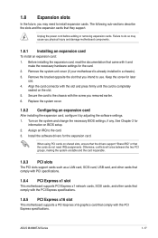
... card is already installed in a chassis). 3. Install the software drivers for the card. 2. When using PCI cards on BIOS setup. 2. ASUS M4N68T-M Series 1-17 Before installing the expansion card, read the documentation that the cards do so may need IRQ assignments. Turn on the slot.... came with it by adjusting the software settings. 1. 1.8 Expansion slots In the future, you may cause you physical injury and damage motherboard components. 1.8.1 Installing an expansion card To install an expansion card: 1. The following sub‑sections describe the slots and the expansion ...
... card is already installed in a chassis). 3. Install the software drivers for the card. 2. When using PCI cards on BIOS setup. 2. ASUS M4N68T-M Series 1-17 Before installing the expansion card, read the documentation that the cards do so may need IRQ assignments. Turn on the slot.... came with it by adjusting the software settings. 1. 1.8 Expansion slots In the future, you may cause you physical injury and damage motherboard components. 1.8.1 Installing an expansion card To install an expansion card: 1. The following sub‑sections describe the slots and the expansion ...
User Manual
Page 31
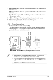
... a VGA monitor or other serial devices. 11. ASUS M4N68T-M Series 1-21 These two 4-pin Universal Serial Bus (USB) ports connect to USB 2.0 devices. 8. This port is purchased separately. COM port. Connect one end of the motherboard high-definition audio capability. • If you want... PIN 1 MIC2 MICPWR Line out_R NC Line out_L PORT1 L PORT1 R PORT2 R SENSE_SEND PORT2 L M4N68T-M V2 HD-audio-compliant Legacy AC'97 pin definition compliant definition M4N68T-M Series Analog front panel connector • We recommend that supports either High Definition Audio or AC`97...
... a VGA monitor or other serial devices. 11. ASUS M4N68T-M Series 1-21 These two 4-pin Universal Serial Bus (USB) ports connect to USB 2.0 devices. 8. This port is purchased separately. COM port. Connect one end of the motherboard high-definition audio capability. • If you want... PIN 1 MIC2 MICPWR Line out_R NC Line out_L PORT1 L PORT1 R PORT2 R SENSE_SEND PORT2 L M4N68T-M V2 HD-audio-compliant Legacy AC'97 pin definition compliant definition M4N68T-M Series Analog front panel connector • We recommend that supports either High Definition Audio or AC`97...

User Manual
Page 33
M4N68T-M Series IDE connector ASUS M4N68T-M Series 1-23 Connect the blue connector to the motherboard's IDE connector, then select one of device(s) - Master Slave Master Slave Cable connector Black Black Gray Black or gray • Pin 20 on the IDE .... This prevents incorrect insertion when you connect the IDE cable. • Use the 80-conductor IDE cable for Ultra DMA 133/100 signal cable. PRI_IDE M4N68T-M V2 PIN1 NOTE:Orient the red markings on the Ultra DMA cable connector. IDE connector (40-1 pin PRI_IDE) The onboard IDE connector is set as "Cable...
M4N68T-M Series IDE connector ASUS M4N68T-M Series 1-23 Connect the blue connector to the motherboard's IDE connector, then select one of device(s) - Master Slave Master Slave Cable connector Black Black Gray Black or gray • Pin 20 on the IDE .... This prevents incorrect insertion when you connect the IDE cable. • Use the 80-conductor IDE cable for Ultra DMA 133/100 signal cable. PRI_IDE M4N68T-M V2 PIN1 NOTE:Orient the red markings on the Ultra DMA cable connector. IDE connector (40-1 pin PRI_IDE) The onboard IDE connector is set as "Cable...
User Manual
Page 34
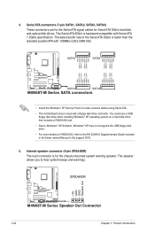
...RSATA_TXN3 RSATA_TXP3 GND GND RSATA_RXN1 RSATA_RXP1 GND RSATA_TXN1 RSATA_TXP1 GND M4N68T-M V2 SATA1 SATA3 M4N68T-M Series SATA connectors • Install the Windows® XP Service Pack 2 or later versions before using Serial ATA. • The motherboard does not provide a floppy disk drive connector. Internal speaker...8226; For more details on RAID/AHCI, refer to hear system beeps and warnings. +5V GND GND Speaker Out SPEAKER M4N68T-M V2 PIN 1 M4N68T-M Series Speaker Out Connector 1-24 Chapter 1: Product introduction The data transfer rate of the Serial ATA 3Gb/s is for ...
...RSATA_TXN3 RSATA_TXP3 GND GND RSATA_RXN1 RSATA_RXP1 GND RSATA_TXN1 RSATA_TXP1 GND M4N68T-M V2 SATA1 SATA3 M4N68T-M Series SATA connectors • Install the Windows® XP Service Pack 2 or later versions before using Serial ATA. • The motherboard does not provide a floppy disk drive connector. Internal speaker...8226; For more details on RAID/AHCI, refer to hear system beeps and warnings. +5V GND GND Speaker Out SPEAKER M4N68T-M V2 PIN 1 M4N68T-M Series Speaker Out Connector 1-24 Chapter 1: Product introduction The data transfer rate of the Serial ATA 3Gb/s is for ...


