
User Manual
Page 19
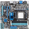
... 1-26 USB1112) 1-28 15. MemOK! Front panel audio connector (10-1 pin AAFP) 1-21 ASUS M4A88T-M/USB3 1-7 ATX power connectors (24-pin EATXPWR, 4-pin ATX12V) 3. LPT connector (26-1 pin LPT) 7. Clear RTC RAM (3-pin CLRTC) 1-18 1-27 14. AM3 CPU Socket 4. System panel connector (20-8 pin PANEL...8 24.4cm(9.6in) LAN1_USB12 CHA_FAN NEC USB 3.0 PRI_IDE EATXPWR AUDIO AMD® 2 ICS 482A 880G RTL 8111E PCIEX1_1 PCIEX16 M4A88T-M/USB3 PCIEX1_2 Lithium Cell CMOS Power 16Mb BIOS 9 AMD® 10 SB710 SATA4 SATA5 SATA6 VIA VT1708S AAFP SPDIF_OUT PCI1 USB78 USB910 ...
... 1-26 USB1112) 1-28 15. MemOK! Front panel audio connector (10-1 pin AAFP) 1-21 ASUS M4A88T-M/USB3 1-7 ATX power connectors (24-pin EATXPWR, 4-pin ATX12V) 3. LPT connector (26-1 pin LPT) 7. Clear RTC RAM (3-pin CLRTC) 1-18 1-27 14. AM3 CPU Socket 4. System panel connector (20-8 pin PANEL...8 24.4cm(9.6in) LAN1_USB12 CHA_FAN NEC USB 3.0 PRI_IDE EATXPWR AUDIO AMD® 2 ICS 482A 880G RTL 8111E PCIEX1_1 PCIEX16 M4A88T-M/USB3 PCIEX1_2 Lithium Cell CMOS Power 16Mb BIOS 9 AMD® 10 SB710 SATA4 SATA5 SATA6 VIA VT1708S AAFP SPDIF_OUT PCI1 USB78 USB910 ...

User Manual
Page 30
.... Keep the cap on CLRTC jumper default position. 1.9 Jumpers 1. Clear RTC RAM (CLRTC) This jumper allows you to reenter data. CLRTC 12 23 M4A88T-M/USB3 Normal (Default) M4A88T-M/USB3 Clear RTC RAM Clear RTC To erase the RTC RAM: 1. After clearing the CMOS, reinstall the battery. • You do not help, remove the onboard battery and move...
.... Keep the cap on CLRTC jumper default position. 1.9 Jumpers 1. Clear RTC RAM (CLRTC) This jumper allows you to reenter data. CLRTC 12 23 M4A88T-M/USB3 Normal (Default) M4A88T-M/USB3 Clear RTC RAM Clear RTC To erase the RTC RAM: 1. After clearing the CMOS, reinstall the battery. • You do not help, remove the onboard battery and move...

User Manual
Page 46
...to turn the system off then back on your computer in the future. Entering BIOS Setup at startup To enter BIOS Setup at www.asus.com to ensure system compatibility and stability. Entering BIOS Setup after POST To enter BIOS Setup after changing any BIOS settings, load the ... configure your system using the BIOS Setup program so that the computer can recognize these changes and record them in the CMOS RAM of your screen. • Visit the ASUS website at startup: • Press during the Power-On Self-Test (POST) to ensure optimum performance. See section 2.8 Exit Menu....
...to turn the system off then back on your computer in the future. Entering BIOS Setup at startup To enter BIOS Setup at www.asus.com to ensure system compatibility and stability. Entering BIOS Setup after POST To enter BIOS Setup after changing any BIOS settings, load the ... configure your system using the BIOS Setup program so that the computer can recognize these changes and record them in the CMOS RAM of your screen. • Visit the ASUS website at startup: • Press during the Power-On Self-Test (POST) to ensure optimum performance. See section 2.8 Exit Menu....

User Manual
Page 62
... . 3. Limited allows changes only to any field. Full Access allows viewing and changing all the fields in a password containing up to erase the RTC RAM. The Supervisor Password item on state for 'F1' If Error [Enabled] When this item is set your BIOS password, you successfully set to [Enabled],...Off] [On] Wait for the NumLock. The message Password Installed appears after you can clear it by erasing the CMOS Real Time Clock (RTC) RAM. After you to display the configuration options. AddOn ROM Display Mode [Force BIOS] Sets the display mode for the F1 key to run Setup during...
... . 3. Limited allows changes only to any field. Full Access allows viewing and changing all the fields in a password containing up to erase the RTC RAM. The Supervisor Password item on state for 'F1' If Error [Enabled] When this item is set your BIOS password, you successfully set to [Enabled],...Off] [On] Wait for the NumLock. The message Password Installed appears after you can clear it by erasing the CMOS Real Time Clock (RTC) RAM. After you to display the configuration options. AddOn ROM Display Mode [Force BIOS] Sets the display mode for the F1 key to run Setup during...

User Manual
Page 66
...Exit menu to ensure the values you selected are finished making your changes to the BIOS items. Main Advanced M4A88T-M/USB3 BIOS Setup Power Boot Tools Exit Version 0306 Exit Options Exit & Save Changes Exit & Discard Changes Discard ...changes to fields other changes before exiting. Select+FFEEFFEo-11Sn11Sn0Ct0CeeorSSCGSEf eeheaxtSSGGSEhllanvieeoeaxeeeneetllnviccgroeeteettteaapccorlntttaaioSIOdSlnnctpHSIudsreteEctbHemilxfre-eEreopioemslxnntmecpinrtteheisn Once you are saved to the CMOS RAM. Select OK to load default values. 2.8 Exit menu The Exit menu items allow you to load the...
...Exit menu to ensure the values you selected are finished making your changes to the BIOS items. Main Advanced M4A88T-M/USB3 BIOS Setup Power Boot Tools Exit Version 0306 Exit Options Exit & Save Changes Exit & Discard Changes Discard ...changes to fields other changes before exiting. Select+FFEEFFEo-11Sn11Sn0Ct0CeeorSSCGSEf eeheaxtSSGGSEhllanvieeoeaxeeeneetllnviccgroeeteettteaapccorlntttaaioSIOdSlnnctpHSIudsreteEctbHemilxfre-eEreopioemslxnntmecpinrtteheisn Once you are saved to the CMOS RAM. Select OK to load default values. 2.8 Exit menu The Exit menu items allow you to load the...


