User Manual
Page 9
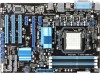
button 1 x 24-pin EATX power connector 1 x 4-pin ATX 12V power connector (continued on the motherboard. *** Refer to DDR3 1066MHz. With ASUS design, this motherboard can support up to www.asus.com for the latest Memory QVL (Qualified Vendors List). 1 x PCIe 2.0 x16 slot 2 x PCIe 2.0 ... panel audio connector 1 x System panel connector 1 x S/PDIF out connector 1 x CPU fan connector 1 x Chassis fan connector 1 x MemOK! M4A87T specifications summary CPU Chipset System Bus Memory Expansion slots Storage / RAID Internal connectors AMD® Socket AM3 for AMD® Phenom™ II / Athlon...
button 1 x 24-pin EATX power connector 1 x 4-pin ATX 12V power connector (continued on the motherboard. *** Refer to DDR3 1066MHz. With ASUS design, this motherboard can support up to www.asus.com for the latest Memory QVL (Qualified Vendors List). 1 x PCIe 2.0 x16 slot 2 x PCIe 2.0 ... panel audio connector 1 x System panel connector 1 x S/PDIF out connector 1 x CPU fan connector 1 x Chassis fan connector 1 x MemOK! M4A87T specifications summary CPU Chipset System Bus Memory Expansion slots Storage / RAID Internal connectors AMD® Socket AM3 for AMD® Phenom™ II / Athlon...

User Manual
Page 11
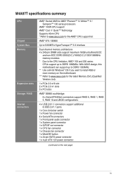
xi M4A87T specifications summary USB LAN BIOS Accessories Support DVD Form factor Supports up to 14 USB 2.0/1.1 ports (8 ports at mid-board, 6 ports at the back panel) Realtek® RTL8111E PCIe Gigabit LAN controller featuring AI NET 2 8Mb Flash ROM, AMI BIOS, PnP, DMI 2.0, WfM 2.0, ACPI 2.0a, SM BIOS 2.5 2 x Serial ATA 6Gb/s cables 1 x I/O shield 1 x User Manual Drivers ASUS Utilities AMD OverDrive Utility (AOD) ASUS Update Anti-Virus software (OEM version) ATX form factor: 12 in x 8.4 in (30.5 cm x 21.3 cm) * Specifications are subject to change without notice.
xi M4A87T specifications summary USB LAN BIOS Accessories Support DVD Form factor Supports up to 14 USB 2.0/1.1 ports (8 ports at mid-board, 6 ports at the back panel) Realtek® RTL8111E PCIe Gigabit LAN controller featuring AI NET 2 8Mb Flash ROM, AMI BIOS, PnP, DMI 2.0, WfM 2.0, ACPI 2.0a, SM BIOS 2.5 2 x Serial ATA 6Gb/s cables 1 x I/O shield 1 x User Manual Drivers ASUS Utilities AMD OverDrive Utility (AOD) ASUS Update Anti-Virus software (OEM version) ATX form factor: 12 in x 8.4 in (30.5 cm x 21.3 cm) * Specifications are subject to change without notice.

User Manual
Page 17
... as the power supply case, to avoid damaging them due to static electricity. • Hold components by the edges to the motherboard, peripherals, or components. ASUS M4A87T 1-5 Failure to do so may cause severe damage to avoid touching the ICs on them. • Whenever you uninstall any component, place it on a grounded... you install motherboard components or change any motherboard settings. • Unplug the power cord from the wall socket before touching any component, switch off the ATX power supply and detach its power cord.
... as the power supply case, to avoid damaging them due to static electricity. • Hold components by the edges to the motherboard, peripherals, or components. ASUS M4A87T 1-5 Failure to do so may cause severe damage to avoid touching the ICs on them. • Whenever you uninstall any component, place it on a grounded... you install motherboard components or change any motherboard settings. • Unplug the power cord from the wall socket before touching any component, switch off the ATX power supply and detach its power cord.

User Manual
Page 19
... SATA6G_6 8 ALC887 SPDIF_OUT PCI3 SB_PWR USB78 USB910 USB1112 USB1314 CLRTC PANEL 14 13 12 11 10 9 1.5.4 Layout contents Connectors/Jumpers/Slots/LED 1. MemOK! ATX power connectors (24-pin EATXPWR, 4-pin ATX12V) 3. DRAM LED (DRAM_LED) Page Connectors/Jumpers/Slots/LED 1-21 8. System panel connector (20-8 pin PANEL...CHA_FAN) 2. Core Unlocker switch (CORE_UNLOCKER) 4. Clear RTC RAM (3-pin CLRTC) 1-19 1-29 11. Front panel audio connector (10-1 pin AAFP) 1-25 ASUS M4A87T 1-7 Core Unlocker LED (02LED1) 5. DDR3 DIMM slots 6. Standby power LED (SB_PWR) 1-29 1-28 13.
... SATA6G_6 8 ALC887 SPDIF_OUT PCI3 SB_PWR USB78 USB910 USB1112 USB1314 CLRTC PANEL 14 13 12 11 10 9 1.5.4 Layout contents Connectors/Jumpers/Slots/LED 1. MemOK! ATX power connectors (24-pin EATXPWR, 4-pin ATX12V) 3. DRAM LED (DRAM_LED) Page Connectors/Jumpers/Slots/LED 1-21 8. System panel connector (20-8 pin PANEL...CHA_FAN) 2. Core Unlocker switch (CORE_UNLOCKER) 4. Clear RTC RAM (3-pin CLRTC) 1-19 1-29 11. Front panel audio connector (10-1 pin AAFP) 1-25 ASUS M4A87T 1-7 Core Unlocker LED (02LED1) 5. DDR3 DIMM slots 6. Standby power LED (SB_PWR) 1-29 1-28 13.

User Manual
Page 34
... the proper orientation and push down firmly until the connectors completely fit. com/PowerSupplyCalculator/PSCalculator.aspx?SLanguage=en-us for an ATX power supply. ATX12V EATXPWR +12V DC +12V DC M4A87T GND GND +3 Volts +12 Volts +12 Volts +5V Standby Power OK PIN 1 GND +5 Volts GND +5 Volts ...and that you use a PSU with 20-pin and 4-pin power plugs, ensure that the 20-pin power plug can provide at http://support.asus. ATX power connectors (24-pin EATXPWR, 4-pin ATX12V) These connectors are designed to use a PSU with higher power output when configuring a system with...
... the proper orientation and push down firmly until the connectors completely fit. com/PowerSupplyCalculator/PSCalculator.aspx?SLanguage=en-us for an ATX power supply. ATX12V EATXPWR +12V DC +12V DC M4A87T GND GND +3 Volts +12 Volts +12 Volts +5V Standby Power OK PIN 1 GND +5 Volts GND +5 Volts ...and that you use a PSU with 20-pin and 4-pin power plugs, ensure that the 20-pin power plug can provide at http://support.asus. ATX power connectors (24-pin EATXPWR, 4-pin ATX12V) These connectors are designed to use a PSU with higher power output when configuring a system with...

User Manual
Page 36
...turning off the system power. 1-24 Chapter 1: Product introduction Connect the chassis power LED cable to hear system beeps and warnings. • ATX power button/soft-off button (2-pin PWRSW) This connector is for the system power button. • Reset button (2-pin RESET) This 2-pin... connector is for the chassis-mounted system warning speaker. PWR Ground Reset Ground PANEL PIN 1 M4A87T IDE_LED PWRSW RESET * Requires an ATX power supply M4A87T System panel connector • System power LED (2-pin PLED) This 2-pin connector is for the HDD Activity LED. System...
...turning off the system power. 1-24 Chapter 1: Product introduction Connect the chassis power LED cable to hear system beeps and warnings. • ATX power button/soft-off button (2-pin PWRSW) This connector is for the system power button. • Reset button (2-pin RESET) This 2-pin... connector is for the chassis-mounted system warning speaker. PWR Ground Reset Ground PANEL PIN 1 M4A87T IDE_LED PWRSW RESET * Requires an ATX power supply M4A87T System panel connector • System power LED (2-pin PLED) This 2-pin connector is for the HDD Activity LED. System...

