
User Manual
Page 4
Contents 1.11 Software support 1-30 1.11.1 Installing an operating system 1-30 1.11.2 Support DVD information 1-30 Chapter 2: BIOS information 2.1 Managing and updating your BIOS 2-1 2.1.1 ASUS Update utility 2-1 2.1.2 ASUS EZ Flash 2 utility 2-2 2.1.3 ASUS CrashFree BIOS utility 2-3 2.2 BIOS setup program 2-4 2.2.1 BIOS menu screen 2-5 2.2.2 Menu bar 2-5 2.2.3 Navigation keys 2-5 2.2.4 Menu items 2-6 2.2.5 Submenu items 2-6 2.2.6 Configuration fields 2-6 2.2.7 Pop-up window 2-6 2.2.8 Scroll bar 2-6 2.2.9 General help 2-6 2.3 Main...
Contents 1.11 Software support 1-30 1.11.1 Installing an operating system 1-30 1.11.2 Support DVD information 1-30 Chapter 2: BIOS information 2.1 Managing and updating your BIOS 2-1 2.1.1 ASUS Update utility 2-1 2.1.2 ASUS EZ Flash 2 utility 2-2 2.1.3 ASUS CrashFree BIOS utility 2-3 2.2 BIOS setup program 2-4 2.2.1 BIOS menu screen 2-5 2.2.2 Menu bar 2-5 2.2.3 Navigation keys 2-5 2.2.4 Menu items 2-6 2.2.5 Submenu items 2-6 2.2.6 Configuration fields 2-6 2.2.7 Pop-up window 2-6 2.2.8 Scroll bar 2-6 2.2.9 General help 2-6 2.3 Main...
User Manual
Page 8
...This user guide contains the information you detect any area where it supports. • Chapter 2: BIOS information This chapter tells how to change system settings through the BIOS Setup menus. If you need when installing and configuring the motherboard. About this guide is organized ...This guide contains the following parts: • Chapter 1: Product introduction This chapter describes the features of the BIOS parameters are not damaged. Operation safety • Before installing the motherboard and adding devices on a stable surface. • If you ...
...This user guide contains the information you detect any area where it supports. • Chapter 2: BIOS information This chapter tells how to change system settings through the BIOS Setup menus. If you need when installing and configuring the motherboard. About this guide is organized ...This guide contains the following parts: • Chapter 1: Product introduction This chapter describes the features of the BIOS parameters are not damaged. Operation safety • Before installing the motherboard and adding devices on a stable surface. • If you ...

User Manual
Page 11
M4A78L-M LE specifications summary Storage / RAID LAN Audio USB Back panel I/O ports Internal I/O connectors BIOS ASUS special features 1 x Ultra DMA 133/100 connector 6 x Serial ATA 3Gb/s connectors support RAID 0, RAID 1, RAID 0+1, and JBOD configurations Atheros&#... 1 x 24-pin EATX power connector 1 x 4-pin ATX 12V power connector 8Mb Flash ROM, AMI BIOS, PnP, DMI2.0, WfM2.0, ACPI2.0a, SM BIOS 2.5 ASUS Q-Fan ASUS CrashFree BIOS3 ASUS EZ Flash2 ASUS MyLogo2 ASUS Express Gate ASUS AI NET2 ASUS EPU-4 Engine (continued on the next page) xi Supports up to support 8-channel audio output.
M4A78L-M LE specifications summary Storage / RAID LAN Audio USB Back panel I/O ports Internal I/O connectors BIOS ASUS special features 1 x Ultra DMA 133/100 connector 6 x Serial ATA 3Gb/s connectors support RAID 0, RAID 1, RAID 0+1, and JBOD configurations Atheros&#... 1 x 24-pin EATX power connector 1 x 4-pin ATX 12V power connector 8Mb Flash ROM, AMI BIOS, PnP, DMI2.0, WfM2.0, ACPI2.0a, SM BIOS 2.5 ASUS Q-Fan ASUS CrashFree BIOS3 ASUS EZ Flash2 ASUS MyLogo2 ASUS Express Gate ASUS AI NET2 ASUS EPU-4 Engine (continued on the next page) xi Supports up to support 8-channel audio output.
User Manual
Page 16
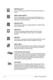
... default settings when the system hangs due to ensure a quiet, cool, and efficient operation. C.P.R. (CPU Parameter Recall) The BIOS C.P.R. C.P.R. ASUS AI NET2 ASUS AI NET2 remotely detects the cable connection immediately after you turn on the environment. 1-4 Chapter 1: Product introduction Simply shut down ...; Turn your favorite photos into 256-color boot logos to their default settings. ASUS CrashFree BIOS 3 ASUS CrashFree BIOS 3 is an auto-recovery tool that allows you to restore a corrupted BIOS file using the bundled support DVD or a USB flash disk that detects the ...
... default settings when the system hangs due to ensure a quiet, cool, and efficient operation. C.P.R. (CPU Parameter Recall) The BIOS C.P.R. C.P.R. ASUS AI NET2 ASUS AI NET2 remotely detects the cable connection immediately after you turn on the environment. 1-4 Chapter 1: Product introduction Simply shut down ...; Turn your favorite photos into 256-color boot logos to their default settings. ASUS CrashFree BIOS 3 ASUS CrashFree BIOS 3 is an auto-recovery tool that allows you to restore a corrupted BIOS file using the bundled support DVD or a USB flash disk that detects the ...

User Manual
Page 19
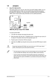
...SB_PWR) Page Connectors/Jumpers/Slots/LED 1-20 9. PCIe x16 / PCIe x1 / PCI slots Page 1-28 1-19 1-25 1-27 1-26 1-28 1-22 1-18 ASUS M4A78L-M LE 1-7 CPU and chassis fan connectors (4-pin CPU_FAN and 3-pin CHA_FAN) 5. Clear RTC RAM (3-pin CLRTC) 1-23 11. System panel connector (10-1 pin F_PANEL... AUDIO AMD® 780L ICS9LPRS485 PCIe Gb LAN VT1708S AAFP PCIEX1_1 SPDIF_OUT PRI_IDE PCIEX16 M4A78L-M LE PCI1 PCI2 AMD® SB710 Lithium Cell CMOS Power SB_PWR SPEAKER SATA1 SATA4 SATA2 SATA5 SATA3 SATA6 8Mb BIOS CLRTC F_PANEL USBPW5-10 USB78 USB910 USB56 15 14 13 2 12 7 8 9...
...SB_PWR) Page Connectors/Jumpers/Slots/LED 1-20 9. PCIe x16 / PCIe x1 / PCI slots Page 1-28 1-19 1-25 1-27 1-26 1-28 1-22 1-18 ASUS M4A78L-M LE 1-7 CPU and chassis fan connectors (4-pin CPU_FAN and 3-pin CHA_FAN) 5. Clear RTC RAM (3-pin CLRTC) 1-23 11. System panel connector (10-1 pin F_PANEL... AUDIO AMD® 780L ICS9LPRS485 PCIe Gb LAN VT1708S AAFP PCIEX1_1 SPDIF_OUT PRI_IDE PCIEX16 M4A78L-M LE PCI1 PCI2 AMD® SB710 Lithium Cell CMOS Power SB_PWR SPEAKER SATA1 SATA4 SATA2 SATA5 SATA3 SATA6 8Mb BIOS CLRTC F_PANEL USBPW5-10 USB78 USB910 USB56 15 14 13 2 12 7 8 9...

User Manual
Page 30
... expansion card To install an expansion card: 1. Remove the system unit cover (if your motherboard is completely seated on the system and change the necessary BIOS settings, if any. Replace the system cover. 1.8.2 Configuring an expansion card After installing the expansion card, configure it and make the necessary hardware settings for...
... expansion card To install an expansion card: 1. Remove the system unit cover (if your motherboard is completely seated on the system and change the necessary BIOS settings, if any. Replace the system cover. 1.8.2 Configuring an expansion card After installing the expansion card, configure it and make the necessary hardware settings for...
User Manual
Page 31
...as system passwords. Shut down the key during the boot process and enter BIOS setup to default values. Keep the cap on CLRTC jumper default position. CLRTC 12 23 M4A78L-M LE Normal (Default) Clear RTC M4A78L-M LE Clear RTC RAM To erase the RTC RAM: 1. Clear RTC RAM ..., use the CPU Parameter Recall (C.P.R) feature. Hold down and reboot the system so the BIOS can clear the CMOS memory of date, time, and system setup parameters by erasing the CMOS RTC RAM data. You can automatically reset parameter settings to reenter data. ASUS M4A78L-M LE 1-19 1.9 Jumpers 1.
...as system passwords. Shut down the key during the boot process and enter BIOS setup to default values. Keep the cap on CLRTC jumper default position. CLRTC 12 23 M4A78L-M LE Normal (Default) Clear RTC M4A78L-M LE Clear RTC RAM To erase the RTC RAM: 1. Clear RTC RAM ..., use the CPU Parameter Recall (C.P.R) feature. Hold down and reboot the system so the BIOS can clear the CMOS memory of date, time, and system setup parameters by erasing the CMOS RTC RAM data. You can automatically reset parameter settings to reenter data. ASUS M4A78L-M LE 1-19 1.9 Jumpers 1.

User Manual
Page 32
...jumper allows you to wake up the compurer from S1 sleep mode (CPU stopped, DRAM refreshed, system running in the BIOS. KBPWR 12 23 +5V +5VSB (Default) M4A78L-M LE M4A78L-M LE Keyboard Power Setting 1-20 Chapter 1: Product introduction USB device wake-up (3-pin USBPW1-4, USBPW5-10) Set these jumpers ... lead, and a corresponding setting in low power mode) using the connected USB devices. USBPW1-4 12 23 +5V +5VSB (Default) M4A78L-M LE USBPW5-10 12 23 +5V +5VSB (Default) M4A78L-M LE USB Device Wake Up 3. This feature requires an ATX power supply that can wake up feature.
...jumper allows you to wake up the compurer from S1 sleep mode (CPU stopped, DRAM refreshed, system running in the BIOS. KBPWR 12 23 +5V +5VSB (Default) M4A78L-M LE M4A78L-M LE Keyboard Power Setting 1-20 Chapter 1: Product introduction USB device wake-up (3-pin USBPW1-4, USBPW5-10) Set these jumpers ... lead, and a corresponding setting in low power mode) using the connected USB devices. USBPW1-4 12 23 +5V +5VSB (Default) M4A78L-M LE USBPW5-10 12 23 +5V +5VSB (Default) M4A78L-M LE USB Device Wake Up 3. This feature requires an ATX power supply that can wake up feature.
User Manual
Page 34
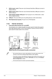
... PIN 1 PIN 1 MIC2 MICPWR Line out_R NC Line out_L PORT1 L PORT1 R PORT2 R SENSE_SEND PORT2 L M4A78L-M LE HD-audio-compliant Legacy AC'97 pin definition compliant definition M4A78L-M LE front panel audio connector • We recommend that supports either High Definition Audio or AC`97 audio standard. USB...connect to [HD Audio]. These two 4-pin Universal Serial Bus (USB) ports connect to this connector, set the Front Panel Select item in the BIOS to USB 2.0 devices. 8. Front panel audio connector (10-1 pin AAFP) This connector is for a PS/2 keyboard. 1.10.2 Internal connectors 1....
... PIN 1 PIN 1 MIC2 MICPWR Line out_R NC Line out_L PORT1 L PORT1 R PORT2 R SENSE_SEND PORT2 L M4A78L-M LE HD-audio-compliant Legacy AC'97 pin definition compliant definition M4A78L-M LE front panel audio connector • We recommend that supports either High Definition Audio or AC`97 audio standard. USB...connect to [HD Audio]. These two 4-pin Universal Serial Bus (USB) ports connect to this connector, set the Front Panel Select item in the BIOS to USB 2.0 devices. 8. Front panel audio connector (10-1 pin AAFP) This connector is for a PS/2 keyboard. 1.10.2 Internal connectors 1....

User Manual
Page 37
...BIOS. GND RSATA_RXN4 RSATA_RXP4 GND RSATA_TXN4 RSATA_TXP4 GND GND RSATA_RXN1 RSATA_RXP1 GND RSATA_TXN1 RSATA_TXP1 GND SATA1 SATA4 GND RSATA_RXN5 RSATA_RXP5 GND RSATA_TXN5 RSATA_TXP5 GND GND RSATA_RXN2 RSATA_RXP2 GND RSATA_TXN2 RSATA_TXP2 GND SATA2 SATA5 GND RSATA_RXN6 RSATA_RXP6 GND RSATA_TXN6 RSATA_TXP6 GND GND RSATA_RXN3 RSATA_RXP3 GND RSATA_TXN3 RSATA_TXP3 GND M4A78L-M LE SATA3 M4A78L-M LE...the type of the Serial ATA 3Gb/s is backward compatible with 133MB/s (Ultra DMA133). ASUS M4A78L-M LE 1-25 4. See 2.3.4 SATA Configuration for Serial ATA 3Gb/s hard disk and optical disk ...
...BIOS. GND RSATA_RXN4 RSATA_RXP4 GND RSATA_TXN4 RSATA_TXP4 GND GND RSATA_RXN1 RSATA_RXP1 GND RSATA_TXN1 RSATA_TXP1 GND SATA1 SATA4 GND RSATA_RXN5 RSATA_RXP5 GND RSATA_TXN5 RSATA_TXP5 GND GND RSATA_RXN2 RSATA_RXP2 GND RSATA_TXN2 RSATA_TXP2 GND SATA2 SATA5 GND RSATA_RXN6 RSATA_RXP6 GND RSATA_TXN6 RSATA_TXP6 GND GND RSATA_RXN3 RSATA_RXP3 GND RSATA_TXN3 RSATA_TXP3 GND M4A78L-M LE SATA3 M4A78L-M LE...the type of the Serial ATA 3Gb/s is backward compatible with 133MB/s (Ultra DMA133). ASUS M4A78L-M LE 1-25 4. See 2.3.4 SATA Configuration for Serial ATA 3Gb/s hard disk and optical disk ...

User Manual
Page 38
... Activity LED. System panel connector (10-1 pin F_PANEL) This connector supports several chassis-mounted functions. PWR LED PWR BTN F_PANEL PIN 1 M4A78L-M LE HD_LED RESET M4A78L-M LE System panel connector • System power LED (2-pin PWRLED) This 2-pin connector is read from or written to this connector. The HDD...mode. • Hard disk drive activity LED (2-pin HDLED) This 2-pin connector is in SLEEP or SOFT-OFF mode depending on the BIOS settings. Connect the chassis power LED cable to this connector. The system power LED lights up or flashes when data is for system ...
... Activity LED. System panel connector (10-1 pin F_PANEL) This connector supports several chassis-mounted functions. PWR LED PWR BTN F_PANEL PIN 1 M4A78L-M LE HD_LED RESET M4A78L-M LE System panel connector • System power LED (2-pin PWRLED) This 2-pin connector is read from or written to this connector. The HDD...mode. • Hard disk drive activity LED (2-pin HDLED) This 2-pin connector is in SLEEP or SOFT-OFF mode depending on the BIOS settings. Connect the chassis power LED cable to this connector. The system power LED lights up or flashes when data is for system ...
User Manual
Page 43
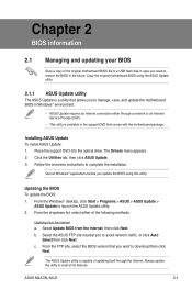
... allows you need to manage, save, and update the motherboard BIOS in the future. ASUS M4A78L-M LE 2-1 Quit all its features. Select Update BIOS from the Internet a. Updating the BIOS To update the BIOS: 1. The ASUS Update utility is a utility that you to download then click Next. Installing ASUS Update To install ASUS Update: 1. The Drivers menu appears. 2. Select the...
... allows you need to manage, save, and update the motherboard BIOS in the future. ASUS M4A78L-M LE 2-1 Quit all its features. Select Update BIOS from the Internet a. Updating the BIOS To update the BIOS: 1. The ASUS Update utility is a utility that you to download then click Next. Installing ASUS Update To install ASUS Update: 1. The Drivers menu appears. 2. Select the...

User Manual
Page 44
...contains the latest BIOS file to prevent system boot failure! 2-2 Chapter 2: BIOS information Updating from the Open window, then click Open. 3. Locate the BIOS file from a BIOS file a. ASUSTek EZ Flash 2 BIOS ROM Utility V3.36 FLASH TYPE: WINBOND W25X80 Current ROM BOARD: M4A78L-M-LE VER: 0302 (H:... to switch between drives until the correct BIOS file is found, then press . Before you to complete the updating process. 2.1.2 ASUS EZ Flash 2 utility The ASUS EZ Flash 2 feature allows you start using this utility, download the latest BIOS file from a file, then click Next...
...contains the latest BIOS file to prevent system boot failure! 2-2 Chapter 2: BIOS information Updating from the Open window, then click Open. 3. Locate the BIOS file from a BIOS file a. ASUSTek EZ Flash 2 BIOS ROM Utility V3.36 FLASH TYPE: WINBOND W25X80 Current ROM BOARD: M4A78L-M-LE VER: 0302 (H:... to switch between drives until the correct BIOS file is found, then press . Before you to complete the updating process. 2.1.2 ASUS EZ Flash 2 utility The ASUS EZ Flash 2 feature allows you start using this utility, download the latest BIOS file from a file, then click Next...

User Manual
Page 45
... so can restore a corrupted BIOS file using the motherboard support DVD or a removable device that ASUS CrashFree BIOS supports vary with motherboard models. Ensure to load the BIOS default settings to the floppy disk drive, if supported. 3. You can cause system boot failure! Turn on again. The utility automatically checks the devices for details. ASUS M4A78L-M LE 2-3
... so can restore a corrupted BIOS file using the motherboard support DVD or a removable device that ASUS CrashFree BIOS supports vary with motherboard models. Ensure to load the BIOS default settings to the floppy disk drive, if supported. 3. You can cause system boot failure! Turn on again. The utility automatically checks the devices for details. ASUS M4A78L-M LE 2-3

User Manual
Page 46
...brief online help to turn the system off then back on. We recommend that you in this chapter are for this motherboard. 2-4 Chapter 2: BIOS information If the system becomes unstable after POST: • Press ++ simultaneously. • Press the reset button on your data or system. They... • Press during the Power-On Self-Test (POST). Entering BIOS Setup at startup To enter BIOS Setup at www.asus.com to enter BIOS Setup using the BIOS Setup program. If you failed to download the latest BIOS file for this motherboard apply to most conditions to ensure system compatibility ...
...brief online help to turn the system off then back on. We recommend that you in this chapter are for this motherboard. 2-4 Chapter 2: BIOS information If the system becomes unstable after POST: • Press ++ simultaneously. • Press the reset button on your data or system. They... • Press during the Power-On Self-Test (POST). Entering BIOS Setup at startup To enter BIOS Setup at www.asus.com to enter BIOS Setup using the BIOS Setup program. If you failed to download the latest BIOS file for this motherboard apply to most conditions to ensure system compatibility ...
User Manual
Page 47
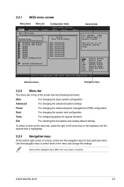
...menu bar, press the right or left arrow key on top of the navigation keys differ from one screen to configure system Time. ASUS M4A78L-M LE 2-5 Submenu items Navigation keys 2.2.2 Menu bar The menu bar on the keyboard until the desired item is highlighted. 2.2.3 Navigation keys...system boot configuration Tools For configuring options for that particular menu. Use [+] or [-] to another. 2.2.1 BIOS menu screen Menu items Menu bar Configuration fields Main Advanced Power BIOS SETUP UTILITY Boot Tools Exit Main Settings System Time [19:34:30] System Date [Fri 07/31/...
...menu bar, press the right or left arrow key on top of the navigation keys differ from one screen to configure system Time. ASUS M4A78L-M LE 2-5 Submenu items Navigation keys 2.2.2 Menu bar The menu bar on the keyboard until the desired item is highlighted. 2.2.3 Navigation keys...system boot configuration Tools For configuring options for that particular menu. Use [+] or [-] to another. 2.2.1 BIOS menu screen Menu items Menu bar Configuration fields Main Advanced Power BIOS SETUP UTILITY Boot Tools Exit Main Settings System Time [19:34:30] System Date [Fri 07/31/...

User Manual
Page 48
... on the screen. configurable, you can change the value of a field, select it for testing purpose. To change the value of options. BIOS SETUP UTILITY Advanced CPU Configuration Module Version: 13.58 AGESA Version: 3.5.3.1 AMD Phenom(tm) II X4 945 Processor Revision: C2 Cache L1: 512KB...window with the configuration options for that item. 2.2.8 Scroll bar A scroll bar appears on the right side of the selected item. 2-6 Chapter 2: BIOS information To display the submenu, select the item and press . 2.2.6 Configuration fields These fields show the values for the menu items. If an item...
... on the screen. configurable, you can change the value of a field, select it for testing purpose. To change the value of options. BIOS SETUP UTILITY Advanced CPU Configuration Module Version: 13.58 AGESA Version: 3.5.3.1 AMD Phenom(tm) II X4 945 Processor Revision: C2 Cache L1: 512KB...window with the configuration options for that item. 2.2.8 Scroll bar A scroll bar appears on the right side of the selected item. 2-6 Chapter 2: BIOS information To display the submenu, select the item and press . 2.2.6 Configuration fields These fields show the values for the menu items. If an item...

User Manual
Page 49
... Select a device item then press to configure system Time. Select [CDROM] if you are not user-configurable. ASUS M4A78L-M LE 2-7 Refer to section 2.2.1 BIOS menu screen for each IDE/SATA device. The BIOS automatically detects the values opposite the dimmed items (Device, Vendor, Size, LBA Mode, Block Mode, PIO Mode,...Not Detected if no IDE/SATA device is installed in the Primary IDE Master/Slave and SATA 5/6 menus. Main Advanced Main Settings Power BIOS SETUP UTILITY Boot Tools Exit System Time [19:34:30] System Date [Fri 07/31/2009] Primary IDE Master Primary IDE Slave...
... Select a device item then press to configure system Time. Select [CDROM] if you are not user-configurable. ASUS M4A78L-M LE 2-7 Refer to section 2.2.1 BIOS menu screen for each IDE/SATA device. The BIOS automatically detects the values opposite the dimmed items (Device, Vendor, Size, LBA Mode, Block Mode, PIO Mode,...Not Detected if no IDE/SATA device is installed in the Primary IDE Master/Slave and SATA 5/6 menus. Main Advanced Main Settings Power BIOS SETUP UTILITY Boot Tools Exit System Time [19:34:30] System Date [Fri 07/31/2009] Primary IDE Master Primary IDE Slave...

User Manual
Page 50
.... • When SATA 1/2/3/4 are configured as [AHCI] and SATA 5/6 are configured as [AHCI], only SATA 1/2/3/4 can access the devices on SATA 5/6 before entering OS. 2-8 Chapter 2: BIOS information OnChip SATA Channel [Enabled] Enables or disables the onboard channel SATA port. Configuration options: [Disabled] [Enabled] SATA Port1 - Setting this item is set to...
.... • When SATA 1/2/3/4 are configured as [AHCI] and SATA 5/6 are configured as [AHCI], only SATA 1/2/3/4 can access the devices on SATA 5/6 before entering OS. 2-8 Chapter 2: BIOS information OnChip SATA Channel [Enabled] Enables or disables the onboard channel SATA port. Configuration options: [Disabled] [Enabled] SATA Port1 - Setting this item is set to...

User Manual
Page 51
...the auto-detected CPU specification. Main Advanced Advanced Settings Power BIOS SETUP UTILITY Boot Tools Exit JumperFree Configuration CPU Configuration Chipset Onboard Devices Configuration PCIPnP USB Configuration Adjust System Frequency/Voltage etc. Configuration options: [Auto] [Manual] [Overclock Profile] [Test Mode] ASUS M4A78L-M LE 2-9 System Memory Displays the auto-detected system memory. ...this menu may vary depending on the AMD CPU type. CPU OverClocking [Auto] Selects the CPU overclocking options to malfunction. The BIOS automatically detects the items in this menu...
...the auto-detected CPU specification. Main Advanced Advanced Settings Power BIOS SETUP UTILITY Boot Tools Exit JumperFree Configuration CPU Configuration Chipset Onboard Devices Configuration PCIPnP USB Configuration Adjust System Frequency/Voltage etc. Configuration options: [Auto] [Manual] [Overclock Profile] [Test Mode] ASUS M4A78L-M LE 2-9 System Memory Displays the auto-detected system memory. ...this menu may vary depending on the AMD CPU type. CPU OverClocking [Auto] Selects the CPU overclocking options to malfunction. The BIOS automatically detects the items in this menu...


