User Manual
Page 8
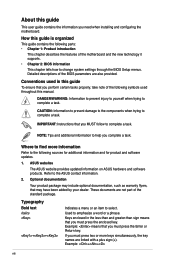
...Indicates a menu or an item to complete a task. Detailed descriptions of the BIOS parameters are not part of the standard package. ASUS websites The ASUS website provides updated information on ASUS hardware and software products. CAUTION: Information to prevent damage to the components when... parts: • Chapter 1: Product introduction This chapter describes the features of the motherboard and the new technology it supports. • Chapter 2: BIOS information This chapter tells how to change system settings through the BIOS Setup menus. Used to emphasize a word or a phrase.
...Indicates a menu or an item to complete a task. Detailed descriptions of the BIOS parameters are not part of the standard package. ASUS websites The ASUS website provides updated information on ASUS hardware and software products. CAUTION: Information to prevent damage to the components when... parts: • Chapter 1: Product introduction This chapter describes the features of the motherboard and the new technology it supports. • Chapter 2: BIOS information This chapter tells how to change system settings through the BIOS Setup menus. Used to emphasize a word or a phrase.
User Manual
Page 17
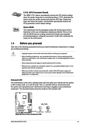
...precautions before you install or remove any motherboard component. C.P.R. This is in soft-off the ATX power supply and detach its packaging comply with the component. • Before you install motherboard components or change any motherboard settings. • Unplug the power cord...and the BIOS automatically restores the CPU parameters to their default settings. Failure to do so may cause severe damage to avoid touching the ICs on them due to static electricity. • Hold components by the edges to the motherboard, peripherals, or components. ASUS M4A785TD-V EVO 1-5
...precautions before you install or remove any motherboard component. C.P.R. This is in soft-off the ATX power supply and detach its packaging comply with the component. • Before you install motherboard components or change any motherboard settings. • Unplug the power cord...and the BIOS automatically restores the CPU parameters to their default settings. Failure to do so may cause severe damage to avoid touching the ICs on them due to static electricity. • Hold components by the edges to the motherboard, peripherals, or components. ASUS M4A785TD-V EVO 1-5
User Manual
Page 29
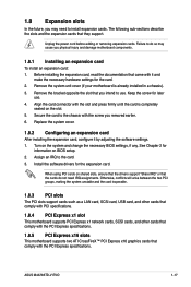
...screw you intend to the chassis with the slot and press firmly until the card is already installed in a chassis). 3. ASUS M4A785TD-V EVO 1-17 Unplug the power cord before adding or removing expansion cards. Before installing the expansion card, read the documentation that ... the expansion card, configure it and make the necessary hardware settings for information on the system and change the necessary BIOS settings, if any. 1.8 Expansion slots In the future, you physical injury and damage motherboard components. 1.8.1 Installing an expansion card To install an expansion card...
...screw you intend to the chassis with the slot and press firmly until the card is already installed in a chassis). 3. ASUS M4A785TD-V EVO 1-17 Unplug the power cord before adding or removing expansion cards. Before installing the expansion card, read the documentation that ... the expansion card, configure it and make the necessary hardware settings for information on the system and change the necessary BIOS settings, if any. 1.8 Expansion slots In the future, you physical injury and damage motherboard components. 1.8.1 Installing an expansion card To install an expansion card...

User Manual
Page 30
You can automatically reset parameter settings to pins 1-2. 3. To erase the RTC RAM: 1. Move the jumper cap from pins 1-2 (default) to reenter data. Hold down and reboot the system so the BIOS can clear the CMOS memory of date, time, and system setup parameters by erasing the CMOS RTC RAM data. ...Clear RTC RAM (CLRTC) This jumper allows you to overclocking. Shut down the key during the boot process and enter BIOS setup to pins 2-3. The onboard button cell battery powers the RAM data in CMOS. Keep the cap on CLRTC jumper default position. Removing the...
You can automatically reset parameter settings to pins 1-2. 3. To erase the RTC RAM: 1. Move the jumper cap from pins 1-2 (default) to reenter data. Hold down and reboot the system so the BIOS can clear the CMOS memory of date, time, and system setup parameters by erasing the CMOS RTC RAM data. ...Clear RTC RAM (CLRTC) This jumper allows you to overclocking. Shut down the key during the boot process and enter BIOS setup to pins 2-3. The onboard button cell battery powers the RAM data in CMOS. Keep the cap on CLRTC jumper default position. Removing the...
User Manual
Page 32
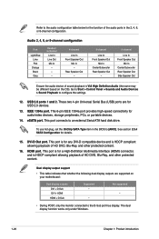
... the OS). This port connects to [AHCI]. IEEE 1394a port. eSATA port. To use hot-plug, set the OnChip SATA Type item in the 2, 4, 6, or 8-channel configuration. Go to Start > Control ...Multimedia Interface (HDMI) connector, and is VIA High Definition Audio (the name may be different based on your motherboard: Dual display outputs DVI + D-Sub DVI + HDMI HDMI + D-Sub Supported • • Not... playback of sound playback is HDCP compliant allowing playback of the audio ports in the BIOS to an external Serial ATA hard disk drive. Rear Speaker Out - 6-channel Line...
... the OS). This port connects to [AHCI]. IEEE 1394a port. eSATA port. To use hot-plug, set the OnChip SATA Type item in the 2, 4, 6, or 8-channel configuration. Go to Start > Control ...Multimedia Interface (HDMI) connector, and is VIA High Definition Audio (the name may be different based on your motherboard: Dual display outputs DVI + D-Sub DVI + HDMI HDMI + D-Sub Supported • • Not... playback of sound playback is HDCP compliant allowing playback of the audio ports in the BIOS to an external Serial ATA hard disk drive. Rear Speaker Out - 6-channel Line...

User Manual
Page 36
..., refer to the RAID/AHCI Supplementary Guide included in the folder named Manual in the BIOS to [RAID]. See 2.3.4 SATA Configuration for Serial ATA 3Gb/s hard disk and optical disk..., SATA5, and SATA6) These connectors are for the Serial ATA signal cables for details. • The motherboard does not provide a floppy disk drive connector. If you install Serial ATA hard disk drives, you can ... versions before using Serial ATA. • If you intend to create a Serial ATA RAID set using these connectors, set . • Due to Windows® XP limitation, Windows® XP may not recognize the...
..., refer to the RAID/AHCI Supplementary Guide included in the folder named Manual in the BIOS to [RAID]. See 2.3.4 SATA Configuration for Serial ATA 3Gb/s hard disk and optical disk..., SATA5, and SATA6) These connectors are for the Serial ATA signal cables for details. • The motherboard does not provide a floppy disk drive connector. If you install Serial ATA hard disk drives, you can ... versions before using Serial ATA. • If you intend to create a Serial ATA RAID set using these connectors, set . • Due to Windows® XP limitation, Windows® XP may not recognize the...
User Manual
Page 37
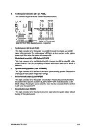
The speaker allows you turn on the BIOS settings. Connect the HDD Activity LED cable to this connector. The system power LED lights up or flashes when data is read from or written to ...; Hard disk drive activity LED (2-pin +IDE_LED) This 2-pin connector is for the HDD Activity LED. Connect the chassis power LED cable to this connector. ASUS M4A785TD-V EVO 1-25 System panel connector (20-8 pin PANEL) This connector supports several chassis-mounted functions. • System power LED (2-pin PLED) This 2-pin connector is for...
The speaker allows you turn on the BIOS settings. Connect the HDD Activity LED cable to this connector. The system power LED lights up or flashes when data is read from or written to ...; Hard disk drive activity LED (2-pin +IDE_LED) This 2-pin connector is for the HDD Activity LED. Connect the chassis power LED cable to this connector. ASUS M4A785TD-V EVO 1-25 System panel connector (20-8 pin PANEL) This connector supports several chassis-mounted functions. • System power LED (2-pin PLED) This 2-pin connector is for...

User Manual
Page 39
...2.4.4 Onboard Device Configuration for an additional Sony/Philips Digital Interface (S/PDIF) port. ASUS M4A785TD-V EVO 1-27 Ensure that you connect a high-definition front panel audio module to this connector to avail of the motherboard high-definition audio capability. • If you want to connect a high definition... of Sound playback is for a chassis-mounted front panel audio I /O module cable to this connector, set the Front Panel Select item in the BIOS to configure the setting. 8. Front panel audio connector (10-1 pin AAFP) This connector is VIA High Definition Audio (the ...
...2.4.4 Onboard Device Configuration for an additional Sony/Philips Digital Interface (S/PDIF) port. ASUS M4A785TD-V EVO 1-27 Ensure that you connect a high-definition front panel audio module to this connector to avail of the motherboard high-definition audio capability. • If you want to connect a high definition... of Sound playback is for a chassis-mounted front panel audio I /O module cable to this connector, set the Front Panel Select item in the BIOS to configure the setting. 8. Front panel audio connector (10-1 pin AAFP) This connector is VIA High Definition Audio (the ...

User Manual
Page 46
...the system properly from the available options using the navigation keys. • The default BIOS settings for this motherboard apply to most conditions to download the latest BIOS file for reference only. If the system becomes unstable after POST, reboot the system by...screen. • Visit the ASUS website at www.asus.com to ensure optimum performance. See section 2.8 Exit Menu. • The BIOS setup screens in this chapter are installing a motherboard, reconfiguring your computer in the future. 2.2 BIOS setup program This motherboard supports a programmable Serial Peripheral ...
...the system properly from the available options using the navigation keys. • The default BIOS settings for this motherboard apply to most conditions to download the latest BIOS file for reference only. If the system becomes unstable after POST, reboot the system by...screen. • Visit the ASUS website at www.asus.com to ensure optimum performance. See section 2.8 Exit Menu. • The BIOS setup screens in this chapter are installing a motherboard, reconfiguring your computer in the future. 2.2 BIOS setup program This motherboard supports a programmable Serial Peripheral ...

User Manual
Page 47
...Exit v02.61 (C)Copyright 1985-2009, American Megatrends, Inc. 2.2.1 BIOS menu screen Menu items Menu bar Configuration fields General help Main Advanced BIOS SETUP UTILITY Power Boot Tools Exit Main Settings System Time [07:32:23] System Date [Tue 01/01/...: Main For changing the basic system configuration Advanced For changing the advanced system settings Power For changing the advanced power management (APM) configuration Boot For changing the system boot configuration Tools For configuring options for that particular menu. ASUS M4A785TD-V EVO 2-5
...Exit v02.61 (C)Copyright 1985-2009, American Megatrends, Inc. 2.2.1 BIOS menu screen Menu items Menu bar Configuration fields General help Main Advanced BIOS SETUP UTILITY Power Boot Tools Exit Main Settings System Time [07:32:23] System Date [Tue 01/01/...: Main For changing the basic system configuration Advanced For changing the advanced system settings Power For changing the advanced power management (APM) configuration Boot For changing the system boot configuration Tools For configuring options for that particular menu. ASUS M4A785TD-V EVO 2-5

User Manual
Page 48
.... A configurable field is enclosed in CMOS then actual and setpoint values may differ. To change the value of the selected item. 2-6 Chapter 2: BIOS information Press the / arrow keys or / keys to display a list of a menu screen when there are items that do not fit on the screen...window with the configuration options for that item. 2.2.8 Scroll bar A scroll bar appears on the right side of options. NOTE: If an invalid ratio is set in brackets, and is a brief description of the field opposite the item. Refer to 2.2.7 Pop-up window. 2.2.7 Pop-up window Scroll bar 2.2.9 General...
.... A configurable field is enclosed in CMOS then actual and setpoint values may differ. To change the value of the selected item. 2-6 Chapter 2: BIOS information Press the / arrow keys or / keys to display a list of a menu screen when there are items that do not fit on the screen...window with the configuration options for that item. 2.2.8 Scroll bar A scroll bar appears on the right side of options. NOTE: If an invalid ratio is set in brackets, and is a brief description of the field opposite the item. Refer to 2.2.7 Pop-up window. 2.2.7 Pop-up window Scroll bar 2.2.9 General...

User Manual
Page 49
.... Main Advanced BIOS SETUP UTILITY Power Boot Tools Exit Main Settings System Time [07:32:23] System Date [Tue 01/01/2002] Use [ENTER], [TAB] or [SHIFT-TAB] to navigate through them. Setting this item to [Auto] allows automatic selection of IDE/SATA drive. ASUS M4A785TD-V EVO 2-7 Primary IDE... Block Mode, PIO Mode, Async DMA, Ultra DMA, and SMART monitoring). 2.3 Main menu When you enter the BIOS Setup program, the Main menu screen appears, giving you to set the system time. 2.3.2 System Date [Day xx/xx/xxxx] Allows you an overview of the basic system information...
.... Main Advanced BIOS SETUP UTILITY Power Boot Tools Exit Main Settings System Time [07:32:23] System Date [Tue 01/01/2002] Use [ENTER], [TAB] or [SHIFT-TAB] to navigate through them. Setting this item to [Auto] allows automatic selection of IDE/SATA drive. ASUS M4A785TD-V EVO 2-7 Primary IDE... Block Mode, PIO Mode, Async DMA, Ultra DMA, and SMART monitoring). 2.3 Main menu When you enter the BIOS Setup program, the Main menu screen appears, giving you to set the system time. 2.3.2 System Date [Day xx/xx/xxxx] Allows you an overview of the basic system information...

User Manual
Page 50
... This item appears only when you to the device occurs one sector at a time if the device supports multisector transfer feature. The BIOS automatically detects the items in AHCI mode under OS. 2.3.5 System Information This menu gives you to [Auto] enables the LBA mode if... the device supports this menu. LBA/Large Mode [Auto] Enables or disables the LBA mode. It allows you set to display the submenu. Processor Displays the auto-detected CPU specification. Configuration options: [Auto] [0] [1] [2] [3] [4] DMA Mode [Auto] Selects the DMA ...
... This item appears only when you to the device occurs one sector at a time if the device supports multisector transfer feature. The BIOS automatically detects the items in AHCI mode under OS. 2.3.5 System Information This menu gives you to [Auto] enables the LBA mode if... the device supports this menu. LBA/Large Mode [Auto] Enables or disables the LBA mode. It allows you set to display the submenu. Processor Displays the auto-detected CPU specification. Configuration options: [Auto] [0] [1] [2] [3] [4] DMA Mode [Auto] Selects the DMA ...
User Manual
Page 51
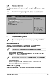
...Manual] ASUS M4A785TD-V EVO 2-9 Select Screen Select Item Enter Go to 550 MHz. Configuration options: [Auto] [Manual] [Overclock Profile] [Test Mode] The following items only appear when you to set the CPU frequency. Take caution when changing the settings of the... [Overclock 2%] [Overclock 5%] [Overclock 8%] [Overclock 10%] GPU OverClocking [Auto] Allows you set CPU Overclocking to malfunction. Main Advanced Advanced Settings Power BIOS SETUP UTILITY Boot Tools Exit JumperFree Configuration CPU Configuration Chipset Onboard Devices Configuration PCIPnP USB Configuration Adjust...
...Manual] ASUS M4A785TD-V EVO 2-9 Select Screen Select Item Enter Go to 550 MHz. Configuration options: [Auto] [Manual] [Overclock Profile] [Test Mode] The following items only appear when you to set the CPU frequency. Take caution when changing the settings of the... [Overclock 2%] [Overclock 5%] [Overclock 8%] [Overclock 10%] GPU OverClocking [Auto] Allows you set CPU Overclocking to malfunction. Main Advanced Advanced Settings Power BIOS SETUP UTILITY Boot Tools Exit JumperFree Configuration CPU Configuration Chipset Onboard Devices Configuration PCIPnP USB Configuration Adjust...
User Manual
Page 52
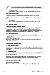
...800 MHz] [1000 MHz] [1200 MHz] [1400 MHz] [1600 MHz] [1800 MHz] [2200 MHz] HT Link Width [Auto] Allows you to set to set the memory clock mode. The value ranges from 1.20000V to adjust the value. Configuration options: [Auto] [Manual] The following item appears only when the... options: [Auto] [8 But] [16 Bit] HT Over Voltage [Auto] Allows you to [Manual]. Configuration options: [Auto] [Manual] 2-10 Chapter 2: BIOS information The following item appears only when the PCIE Overclocking item is set the HyperTransport over voltage. PCIE Overclocking [Auto] Allows you to...
...800 MHz] [1000 MHz] [1200 MHz] [1400 MHz] [1600 MHz] [1800 MHz] [2200 MHz] HT Link Width [Auto] Allows you to set to set the memory clock mode. The value ranges from 1.20000V to adjust the value. Configuration options: [Auto] [Manual] The following item appears only when the... options: [Auto] [8 But] [16 Bit] HT Over Voltage [Auto] Allows you to [Manual]. Configuration options: [Auto] [Manual] 2-10 Chapter 2: BIOS information The following item appears only when the PCIE Overclocking item is set the HyperTransport over voltage. PCIE Overclocking [Auto] Allows you to...

User Manual
Page 54
...Microcode Updation [Enabled] Enables or disables Microcode Updation. When this item is set to [All Cores], the processor has the best overclocking performance. Configuration options: [Disabled] [Auto] [All Cores] [Per Core] 2-12 Chapter 2: BIOS information The value ranges from 1.5000V to 2.2050V with a 0.00625V ...and voltage will be reduced during the system halt state to [Auto], the BIOS automatically adjusts this item is set to [Per Core], the processor's overclocking capability is set to decrease power consumption. When this function. GART Error Reporting [Disabled] This ...
...Microcode Updation [Enabled] Enables or disables Microcode Updation. When this item is set to [All Cores], the processor has the best overclocking performance. Configuration options: [Disabled] [Auto] [All Cores] [Per Core] 2-12 Chapter 2: BIOS information The value ranges from 1.5000V to 2.2050V with a 0.00625V ...and voltage will be reduced during the system halt state to [Auto], the BIOS automatically adjusts this item is set to [Per Core], the processor's overclocking capability is set to decrease power consumption. When this function. GART Error Reporting [Disabled] This ...

User Manual
Page 56
... [ECP] [EPP+ECP] Parallel Port IRQ [IRQ7] Configuration options: [IRQ5] [IRQ7] 2-14 Chapter 2: BIOS information Configuration options: [Auto] [32MB] [64MB] [128MB] [256MB] The following item appears when you set the Internal Graphics Mode item to [UMA] UMAFrame Buffer Size [Auto] Allows you to select the SlidePort Clock speed...[DDR3-1580 MHz] [DDR3-1610 MHz] [DDR31640 MHz] [DDR3-1670 MHz] [DDR3-1700 MHz] SP OverVoltage [1.5V] Allows you to set the Internal Graphics Mode item to [SlidePort] SlidePort Clock Speed [DDR3-1333 MHz] Allows you to select the Parallel Port base addresses. The ...
... [ECP] [EPP+ECP] Parallel Port IRQ [IRQ7] Configuration options: [IRQ5] [IRQ7] 2-14 Chapter 2: BIOS information Configuration options: [Auto] [32MB] [64MB] [128MB] [256MB] The following item appears when you set the Internal Graphics Mode item to [UMA] UMAFrame Buffer Size [Auto] Allows you to select the SlidePort Clock speed...[DDR3-1580 MHz] [DDR3-1610 MHz] [DDR31640 MHz] [DDR3-1670 MHz] [DDR3-1700 MHz] SP OverVoltage [1.5V] Allows you to set the Internal Graphics Mode item to [SlidePort] SlidePort Clock Speed [DDR3-1333 MHz] Allows you to select the Parallel Port base addresses. The ...

User Manual
Page 57
... either PCI/PnP or legacy ISA devices, and setting the memory size block for PCI/PnP devices. Configuration options: [No] [Yes] 2.4.6 USB Configuration The items in the system. Configuration options: [Disabled] [Enabled] ASUS M4A785TD-V EVO 2-15 HDAudio Controller [Enabled] Enables or disables ...Allows you to enable or disable the onboard 1394 device support. Configuration options: [AC97] [HD Audio] SPDIF_OUT Mode Setting [SPDIF Output] Allows you to [No], BIOS configures all the devices in this item is detected, the item shows None. Configuration options: [Enabled] [Disabled] ...
... either PCI/PnP or legacy ISA devices, and setting the memory size block for PCI/PnP devices. Configuration options: [No] [Yes] 2.4.6 USB Configuration The items in the system. Configuration options: [Disabled] [Enabled] ASUS M4A785TD-V EVO 2-15 HDAudio Controller [Enabled] Enables or disables ...Allows you to enable or disable the onboard 1394 device support. Configuration options: [AC97] [HD Audio] SPDIF_OUT Mode Setting [SPDIF Output] Allows you to [No], BIOS configures all the devices in this item is detected, the item shows None. Configuration options: [Enabled] [Disabled] ...

User Manual
Page 58
...device is plugged in HiSpeed (480Mbps) or Full Speed (12Mbps). USB Mass Storage Device Configuration USB Mass Storage Reset Delay [20 Sec] Sets the maximum time that the BIOS waits for the USB storage device to detect the presence of USB devices at startup. Main Advanced Power... BIOS SETUP UTILITY Boot Tools Exit Power Settings Suspend Mode [Auto] ACPI 2.0 Support [Disabled] ACPI APIC support [Enabled] Select the ACPI state used for system suspend. Select an ...
...device is plugged in HiSpeed (480Mbps) or Full Speed (12Mbps). USB Mass Storage Device Configuration USB Mass Storage Reset Delay [20 Sec] Sets the maximum time that the BIOS waits for the USB storage device to detect the presence of USB devices at startup. Main Advanced Power... BIOS SETUP UTILITY Boot Tools Exit Power Settings Suspend Mode [Auto] ACPI 2.0 Support [Disabled] ACPI APIC support [Enabled] Select the ACPI state used for system suspend. Select an ...
User Manual
Page 60
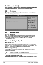
...that smartly adjusts the fan speeds for option ROM. The number of devices installed in the system. AddOn ROM Display Mode [Force BIOS] Sets the display mode for more efficient system operation. A virtual floppy disk drive (Floppy Drive B:) may appear when you to enable... or disable the full screen logo display feature. Select an item then press to use the ASUS MyLogo2™ feature. Configuration options: [Force BIOS] [Keep Current] 2-18 Chapter 2: BIOS information Select Screen Select Item Enter Go to change the system boot options. Configuration options: [Disabled]...
...that smartly adjusts the fan speeds for option ROM. The number of devices installed in the system. AddOn ROM Display Mode [Force BIOS] Sets the display mode for more efficient system operation. A virtual floppy disk drive (Floppy Drive B:) may appear when you to enable... or disable the full screen logo display feature. Select an item then press to use the ASUS MyLogo2™ feature. Configuration options: [Force BIOS] [Keep Current] 2-18 Chapter 2: BIOS information Select Screen Select Item Enter Go to change the system boot options. Configuration options: [Disabled]...


