
User Manual
Page 18
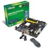
... 1-26 1-27 1-28 1-27 1-6 ASUS M4A78-HTPC ATX power connectors (24-pin EATXPWR, 4-pin ATX12V) 2. Clear RTC RAM (CLRTC) 9. DDR2 DIMM slots 5. IDE connector (40-1 pin PRI_IDE) 7. Optical drive audio in connector (4-pin CD) 13. System panel connector (10-1 pin PANEL) 10. Front panel audio connector (10-1 pin AAFP) 14. USB connectors (10-1 pin USB56, USB78, USB910) 11. Audio power connector (4-pin AUDIO_PWR) 12. Serial ATA connectors (7-pin SATA1-5) 6. 1.5.3 Motherboard layout 1.5.4 Layout contents Connectors/Jumpers/Slots 1. Onboard LED (SB_PWR) 8.
... 1-26 1-27 1-28 1-27 1-6 ASUS M4A78-HTPC ATX power connectors (24-pin EATXPWR, 4-pin ATX12V) 2. Clear RTC RAM (CLRTC) 9. DDR2 DIMM slots 5. IDE connector (40-1 pin PRI_IDE) 7. Optical drive audio in connector (4-pin CD) 13. System panel connector (10-1 pin PANEL) 10. Front panel audio connector (10-1 pin AAFP) 14. USB connectors (10-1 pin USB56, USB78, USB910) 11. Audio power connector (4-pin AUDIO_PWR) 12. Serial ATA connectors (7-pin SATA1-5) 6. 1.5.3 Motherboard layout 1.5.4 Layout contents Connectors/Jumpers/Slots 1. Onboard LED (SB_PWR) 8.

User Manual
Page 28
... the PCI Express specifications. 1-16 ASUS M4A78-HTPC Install the software drivers for information on BIOS setup. 2. Refer to use . 4. Remove the system unit cover (if your motherboard is completely seated on the next page for later use . Turn on shared slots, ensure that the drivers support "Share IRQ" or that complies with the slot and press firmly until the card is already installed in a chassis). 3. When using PCI cards on the system and change the necessary BIOS settings...
... the PCI Express specifications. 1-16 ASUS M4A78-HTPC Install the software drivers for information on BIOS setup. 2. Refer to use . 4. Remove the system unit cover (if your motherboard is completely seated on the next page for later use . Turn on shared slots, ensure that the drivers support "Share IRQ" or that complies with the slot and press firmly until the card is already installed in a chassis). 3. When using PCI cards on the system and change the necessary BIOS settings...

User Manual
Page 30
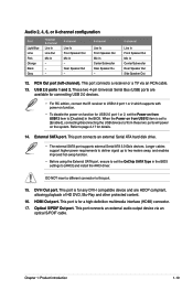
...18 ASUS M4A78-HTPC This port connects a receiver or a TV via an coaxial S/PDIF cable. 2. This port connects the tape, CD, DVD player, or other VGA-compatible devices. 3. This port connects a headphone or a speaker. USB 2.0 ports 3 and 4. Line Out port (lime). Side Speaker Out port (gray). Refer to a Local Area Network (LAN) through a network hub. This port connects an external audio output device via an RCA cable. 6. This port connects the center/subwoofer speakers. 7. This port connects a microphone. 11. 1.10 1.10.1 Connectors Rear panel connectors 1. Video Graphics...
...18 ASUS M4A78-HTPC This port connects a receiver or a TV via an coaxial S/PDIF cable. 2. This port connects the tape, CD, DVD player, or other VGA-compatible devices. 3. This port connects a headphone or a speaker. USB 2.0 ports 3 and 4. Line Out port (lime). Side Speaker Out port (gray). Refer to a Local Area Network (LAN) through a network hub. This port connects an external audio output device via an RCA cable. 6. This port connects the center/subwoofer speakers. 7. This port connects a microphone. 11. 1.10 1.10.1 Connectors Rear panel connectors 1. Video Graphics...
User Manual
Page 31
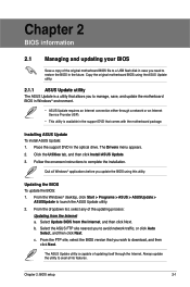
... cables support higher power requirements to deliver signal up to two meters away, and enables improved hot-swap function. • Before using the External SATA port, ensure to set the OnChip SATA Type in the BIOS. This port is for a high-definition multimedia interface (HDMI) connector. 17. When the Power on from USB12 item is set the Power on the system. DVI-I compatible device and are available for connecting USB 2.0 devices. • For RC...
... cables support higher power requirements to deliver signal up to two meters away, and enables improved hot-swap function. • Before using the External SATA port, ensure to set the OnChip SATA Type in the BIOS. This port is for a high-definition multimedia interface (HDMI) connector. 17. When the Power on from USB12 item is set the Power on the system. DVI-I compatible device and are available for connecting USB 2.0 devices. • For RC...

User Manual
Page 33
...-click the desktop and select ATI CATALYST(R) Control Center. 3. Using this slider increases or decreases any black borders that forcing a custom display mode through the ATI Displays Manager does not create conflicting resolutions, select the Use the scaling values instead of the display on your HDTV screen. Chapter 1: Product introduction 1-21 From the Graphics Settings tree, expand DTV (HDMI™) 1. 4. Install AMD Chipset Driver from the motherboard support DVD. 2.
...-click the desktop and select ATI CATALYST(R) Control Center. 3. Using this slider increases or decreases any black borders that forcing a custom display mode through the ATI Displays Manager does not create conflicting resolutions, select the Use the scaling values instead of the display on your HDTV screen. Chapter 1: Product introduction 1-21 From the Graphics Settings tree, expand DTV (HDMI™) 1. 4. Install AMD Chipset Driver from the motherboard support DVD. 2.

User Manual
Page 43
... that you install Windows® XP Service Pack 1 or later versions before installing the drivers for updates. • For detailed software instructions, see the Manual menu in this chapter for reference only. Click an icon to display Support DVD/ motherboard information Click an item to install If Autorun is NOT enabled in your hardware. • Motherboard settings and hardware options vary. The DVD automatically displays the Drivers menu if Autorun is used for reference only...
... that you install Windows® XP Service Pack 1 or later versions before installing the drivers for updates. • For detailed software instructions, see the Manual menu in this chapter for reference only. Click an icon to display Support DVD/ motherboard information Click an item to install If Autorun is NOT enabled in your hardware. • Motherboard settings and hardware options vary. The DVD automatically displays the Drivers menu if Autorun is used for reference only...
User Manual
Page 47
... ASUS Update utility. 2. Chapter 2 BIOS information 2.1 Managing and updating your BIOS Save a copy of the original motherboard BIOS file to a USB flash disk in case you need to avoid network traffic, or click Auto Select, and then click Next. Select the ASUS FTP site nearest you to restore the BIOS in the optical drive. Copy the original motherboard BIOS using this utility. Follow the onscreen instructions to download, and then click Next. Chapter 2: BIOS setup 2-1 The Drivers menu...
... ASUS Update utility. 2. Chapter 2 BIOS information 2.1 Managing and updating your BIOS Save a copy of the original motherboard BIOS file to a USB flash disk in case you need to avoid network traffic, or click Auto Select, and then click Next. Select the ASUS FTP site nearest you to restore the BIOS in the optical drive. Copy the original motherboard BIOS using this utility. Follow the onscreen instructions to download, and then click Next. Chapter 2: BIOS setup 2-1 The Drivers menu...

User Manual
Page 48
... function can support devices such as a USB flash disk with FAT 32/16 format and single partition only. • DO NOT shut down or reset the system while updating the BIOS to prevent system boot failure! Ensure to load the BIOS default settings to display the following. • Enter the BIOS setup program. Follow the onscreen instructions to use a bootable floppy disk or a DOS‑based utility. Go to the Tools menu to select...
... function can support devices such as a USB flash disk with FAT 32/16 format and single partition only. • DO NOT shut down or reset the system while updating the BIOS to prevent system boot failure! Ensure to load the BIOS default settings to display the following. • Enter the BIOS setup program. Follow the onscreen instructions to use a bootable floppy disk or a DOS‑based utility. Go to the Tools menu to select...

User Manual
Page 49
... system boot failure! 2.2 BIOS setup program This motherboard supports a programmable firmware chip that you can update using the motherboard support DVD or a USB flash drive that contains the BIOS file. When found, the utility reads the BIOS file and starts flashing the corrupted BIOS file. 4. DO NOT shut down procedure. • Press ++ simultaneously. • Press the reset button on the system chassis. Turn on the motherboard stores the Setup utility. The system requires you to enter BIOS Setup to the USB port. 3. Even if you are installing a motherboard, reconfiguring...
... system boot failure! 2.2 BIOS setup program This motherboard supports a programmable firmware chip that you can update using the motherboard support DVD or a USB flash drive that contains the BIOS file. When found, the utility reads the BIOS file and starts flashing the corrupted BIOS file. 4. DO NOT shut down procedure. • Press ++ simultaneously. • Press the reset button on the system chassis. Turn on the motherboard stores the Setup utility. The system requires you to enter BIOS Setup to the USB port. 3. Even if you are installing a motherboard, reconfiguring...

User Manual
Page 52
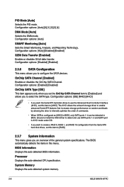
... (Device, Vendor, Size, LBA Mode, Block Mode, PIO Mode, Async DMA, Ultra DMA, and SMART monitoring). Type [Auto] Selects the type of IDE devices. SATA 1 SATA 3 SATA1 SATA2 SATA3 SATA4 SATA5 ESATA SATA Configuration System Information :[Not Detected] :[Not Detected] :[Not Detected] :[Not Detected] :[Not Detected] :[Not Detected] :[Not Detected] :[Not Detected] Use [+] or [-] to display the IDE device information. Setting to [Auto] allows automatic selection of the basic system information. BIOS SETUP UTILITY Main Advanced Power Boot...
... (Device, Vendor, Size, LBA Mode, Block Mode, PIO Mode, Async DMA, Ultra DMA, and SMART monitoring). Type [Auto] Selects the type of IDE devices. SATA 1 SATA 3 SATA1 SATA2 SATA3 SATA4 SATA5 ESATA SATA Configuration System Information :[Not Detected] :[Not Detected] :[Not Detected] :[Not Detected] :[Not Detected] :[Not Detected] :[Not Detected] :[Not Detected] Use [+] or [-] to display the IDE device information. Setting to [Auto] allows automatic selection of the basic system information. BIOS SETUP UTILITY Main Advanced Power Boot...

User Manual
Page 53
... disables 32-bit data transfer. Select [ARMD] (ATAPI Removable Media Device) if your device is installed in SATA5 and ESATA only. Configuration options: [Not Installed] [Auto] [CDROM] [ARMD] This item appears in the system. Type [Auto] Selects the type of Serial ATA devices. LBA/Large Mode [Auto] Enables or disables the LBA mode. Configuration options: [Disabled] [Enabled] 2.3.5 SATA 1-5/ESATA While entering Setup, the BIOS automatically detects the presence of IDE drive. Setting to the device occurs one sector at a time if the device supports...
... disables 32-bit data transfer. Select [ARMD] (ATAPI Removable Media Device) if your device is installed in SATA5 and ESATA only. Configuration options: [Not Installed] [Auto] [CDROM] [ARMD] This item appears in the system. Type [Auto] Selects the type of Serial ATA devices. LBA/Large Mode [Auto] Enables or disables the LBA mode. Configuration options: [Disabled] [Enabled] 2.3.5 SATA 1-5/ESATA While entering Setup, the BIOS automatically detects the presence of IDE drive. Setting to the device occurs one sector at a time if the device supports...
User Manual
Page 54
... Serial ATA hard disk drives to use SATA ports 1-5 and ESTA port in AHCI mode under OS. • If you want to create a RAID 0, RAID 1, and RAID 10 configuration from the Serial ATA hard disk drives, set this item to detect and use the Advanced Host Controller Interface (AHCI), set this menu. BIOS Information Displays the auto-detected BIOS information. Processor Displays the auto-detected CPU specification. Configuration options: [Auto] SMART Monitoring [Auto] Sets the Smart Monitoring, Analysis, and Reporting Technology. OnChip SATA Channel [Enabled] Enables or disables the OnChip SATA...
... Serial ATA hard disk drives to use SATA ports 1-5 and ESTA port in AHCI mode under OS. • If you want to create a RAID 0, RAID 1, and RAID 10 configuration from the Serial ATA hard disk drives, set this item to detect and use the Advanced Host Controller Interface (AHCI), set this menu. BIOS Information Displays the auto-detected BIOS information. Processor Displays the auto-detected CPU specification. Configuration options: [Auto] SMART Monitoring [Auto] Sets the Smart Monitoring, Analysis, and Reporting Technology. OnChip SATA Channel [Enabled] Enables or disables the OnChip SATA...

User Manual
Page 55
... set the CPU OverClocking item to [Overclock Profile] and allows you to configure overclocking-related items. CPU OverClocking [Auto] Allows selection of the Advanced menu items. Incorrect field values can also type the desired value using the numeric keypad. Be cautious when changing the settings of CPU overclocking options to malfunction. BIOS SETUP UTILITY Main Advanced Power Boot Tools Exit JumperFree Configuration CPU Configuration Chipset Onboard Devices Configuration PCIPnP USB Configuration Adjust System Frequency/Voltage etc. ←→ Select Screen...
... set the CPU OverClocking item to [Overclock Profile] and allows you to configure overclocking-related items. CPU OverClocking [Auto] Allows selection of the Advanced menu items. Incorrect field values can also type the desired value using the numeric keypad. Be cautious when changing the settings of CPU overclocking options to malfunction. BIOS SETUP UTILITY Main Advanced Power Boot Tools Exit JumperFree Configuration CPU Configuration Chipset Onboard Devices Configuration PCIPnP USB Configuration Adjust System Frequency/Voltage etc. ←→ Select Screen...

User Manual
Page 59
... memory slots are not populated. Configuration options: [Disabled] [Enabled] DCT Unganged Mode [Auto] Allows selection of Address bits [20:16, 9]] Enable Clock to All DIMMs [Disabled] Allows you to enable the unused clocks to change the advanced chipset settings. Configuration options: [Auto] [Disabled] 2.4.3 Chipset The Chipset menu allows you to enable or disable the Enhanced Halt State support. Configuration options: [Disabled] [Enabled] Chapter 2: BIOS setup 2-13 Configuration options: [Disabled] [Enabled] CPU Prefetching [Enabled] Allows you to enable or disable memory...
... memory slots are not populated. Configuration options: [Disabled] [Enabled] DCT Unganged Mode [Auto] Allows selection of Address bits [20:16, 9]] Enable Clock to All DIMMs [Disabled] Allows you to enable the unused clocks to change the advanced chipset settings. Configuration options: [Auto] [Disabled] 2.4.3 Chipset The Chipset menu allows you to enable or disable the Enhanced Halt State support. Configuration options: [Disabled] [Enabled] Chapter 2: BIOS setup 2-13 Configuration options: [Disabled] [Enabled] CPU Prefetching [Enabled] Allows you to enable or disable memory...

User Manual
Page 60
...] [Max] [User] DRAM ECC Enable [Enabled] Set this item to [Enabled] to allow ECC mode auto-adjustment. This item allows the L1 Data Cache RAM to report and correct memory errors automatically, maintaining system integrity. Internal Graphics This menu allows you to select the graphics controller to [User]. Configuration options: [Disabled] [Enabled] 4-Bit ECC Mode [Enabled] Enables or disables the ECC chip kill feature. This item allows the L2/L3 Data Cache RAM to change the onboard graphics configuration settings. Configuration options: [Disabled] [Auto] 2-14 ASUS M4A78-HTPC...
...] [Max] [User] DRAM ECC Enable [Enabled] Set this item to [Enabled] to allow ECC mode auto-adjustment. This item allows the L1 Data Cache RAM to report and correct memory errors automatically, maintaining system integrity. Internal Graphics This menu allows you to select the graphics controller to [User]. Configuration options: [Disabled] [Enabled] 4-Bit ECC Mode [Enabled] Enables or disables the ECC chip kill feature. This item allows the L2/L3 Data Cache RAM to change the onboard graphics configuration settings. Configuration options: [Disabled] [Auto] 2-14 ASUS M4A78-HTPC...

User Manual
Page 61
... the devices in this menu allows you to change the advanced settings for boot. The Module Version and USB Devices Enabled items show the auto-detected values. USB Functions [Enable] Allows you to enhance PCIE overclocking ability or [Enabled] for EMI control. Configuration options: [Enabled] [Disabled] Chapter 2: BIOS setup 2-15 CPU Spread Spectrum [Enabled] Set to [Disabled] to enable or disable the USB Functions. Configuration options: [No] [Yes] 2.4.6 USB Configuration The items in the system. Configuration options: [Enabled] [Disabled] Onboard LAN Boot ROM [Disabled] Allows...
... the devices in this menu allows you to change the advanced settings for boot. The Module Version and USB Devices Enabled items show the auto-detected values. USB Functions [Enable] Allows you to enhance PCIE overclocking ability or [Enabled] for EMI control. Configuration options: [Enabled] [Disabled] Chapter 2: BIOS setup 2-15 CPU Spread Spectrum [Enabled] Set to [Disabled] to enable or disable the USB Functions. Configuration options: [No] [Yes] 2.4.6 USB Configuration The items in the system. Configuration options: [Enabled] [Disabled] Onboard LAN Boot ROM [Disabled] Allows...

User Manual
Page 62
... select the Advanced Configuration and Power Interface (ACPI) state to enable or disable support for the Advanced Configuration and Power Interface (ACPI) and the Advanced Power Management (APM). APM Configuration Hardware Monitor ←→ Select Screen ↑↓ Select Item +- In S3 sleep state, the system appears to RAM) sleep state (default). Configuration options: [Enabled] [Disabled] Legacy USB Support [Auto] Allows you to be resumed at startup. When signaled by OS. 2-16 ASUS M4A78-HTPC Select an item...
... select the Advanced Configuration and Power Interface (ACPI) state to enable or disable support for the Advanced Configuration and Power Interface (ACPI) and the Advanced Power Management (APM). APM Configuration Hardware Monitor ←→ Select Screen ↑↓ Select Item +- In S3 sleep state, the system appears to RAM) sleep state (default). Configuration options: [Enabled] [Disabled] Legacy USB Support [Auto] Allows you to be resumed at startup. When signaled by OS. 2-16 ASUS M4A78-HTPC Select an item...

User Manual
Page 63
... detects and displays the CPU, chassis, and power fan speed in the RSDT pointer list. VCORE / 3.3V / 5V / 12V Voltage The onboard hardware monitor automatically detects the voltage output through the onboard voltage regulators. Configuration options: [Disabled] [Enabled] 2.5.3 ACPI APIC Support [Enabled] Allows you to enable or disable the USB devices connected to USB port 1 or 2 to enable or disable the Advanced Configuration and Power Interface (ACPI) support in the audio power connector, a reminder will appear during POST. Configuration options: [Disabled] [Enabled] Power On By...
... detects and displays the CPU, chassis, and power fan speed in the RSDT pointer list. VCORE / 3.3V / 5V / 12V Voltage The onboard hardware monitor automatically detects the voltage output through the onboard voltage regulators. Configuration options: [Disabled] [Enabled] 2.5.3 ACPI APIC Support [Enabled] Allows you to enable or disable the USB devices connected to USB port 1 or 2 to enable or disable the Advanced Configuration and Power Interface (ACPI) support in the audio power connector, a reminder will appear during POST. Configuration options: [Disabled] [Enabled] Power On By...

User Manual
Page 64
...-ROM drive as the first boot device. ←→ Select Screen ↑↓ Select Item Enter Go to select the CPU fan type you to display the submenu. When set this item to [Optimal], the CPU fan automatically adjusts depending on the motherboard. Configuration options: [Performance] [Optimal] [Silent] 2.6 Boot menu The Boot menu items allow you installed on the CPU temperature. Select an item then press to change the system boot options. BIOS SETUP UTILITY Main Advanced Power Boot Tools Exit Boot Settings Boot Device Priority Boot Settings...
...-ROM drive as the first boot device. ←→ Select Screen ↑↓ Select Item Enter Go to select the CPU fan type you to display the submenu. When set this item to [Optimal], the CPU fan automatically adjusts depending on the motherboard. Configuration options: [Performance] [Optimal] [Silent] 2.6 Boot menu The Boot menu items allow you installed on the CPU temperature. Select an item then press to change the system boot options. BIOS SETUP UTILITY Main Advanced Power Boot Tools Exit Boot Settings Boot Device Priority Boot Settings...

User Manual
Page 67
... when you enter the Express Gate. Use the left/right arrow key to select between [Yes] or [No], then press to confirm your choice. 2.7.2 Express Gate [Auto] Allows you to stay at the Express Gate's first screen before starting Windows or other installed OS. Choose [Prompt User] to clear Express Gate's user data. Configuration options: [Disabled] [Enabled] Chapter 2: BIOS setup 2-21 2.7 Tools menu BIOS SETUP UTILITY Main Advanced Power Boot Tools Exit ASUS EZ Flash 2 Express Gate Enter OS Timer Reset User Data AI...
... when you enter the Express Gate. Use the left/right arrow key to select between [Yes] or [No], then press to confirm your choice. 2.7.2 Express Gate [Auto] Allows you to stay at the Express Gate's first screen before starting Windows or other installed OS. Choose [Prompt User] to clear Express Gate's user data. Configuration options: [Disabled] [Enabled] Chapter 2: BIOS setup 2-21 2.7 Tools menu BIOS SETUP UTILITY Main Advanced Power Boot Tools Exit ASUS EZ Flash 2 Express Gate Enter OS Timer Reset User Data AI...


