
User Manual
Page 31
Reading flash ..... exe 2 DOS afudos /o[filename filename A:\>afudos /oOLDBIOS1.rom 3. 按下 afudos /oOLDBIOS1.rom AMI Firmware Update Utility - All rights reserved. done Write to file...... ok A:\> 當 BIOS DOS 31 Version 1.19(ASUS V2.07(03.11.24BB)) Copyright (C) 2002 American Megatrends, Inc. BIOS 2.1 使用 AFUDOS BIOS AFUDOS DOS BIOS BIOS 程式。AFUDOS BIOS BIOS BIOS 程式 BIOS 程式。 1.2MB BIOS 1 AFUDOS 程式(afudos.
Reading flash ..... exe 2 DOS afudos /o[filename filename A:\>afudos /oOLDBIOS1.rom 3. 按下 afudos /oOLDBIOS1.rom AMI Firmware Update Utility - All rights reserved. done Write to file...... ok A:\> 當 BIOS DOS 31 Version 1.19(ASUS V2.07(03.11.24BB)) Copyright (C) 2002 American Megatrends, Inc. BIOS 2.1 使用 AFUDOS BIOS AFUDOS DOS BIOS BIOS 程式。AFUDOS BIOS BIOS BIOS 程式 BIOS 程式。 1.2MB BIOS 1 AFUDOS 程式(afudos.

User Manual
Page 32
...; A:\>afudos /iP5B-VM DO.ROM AMI Firmware Update Utility - 更新 BIOS 程式 AFUDOS BIOS 程式。 1 tw.asus.com BIOS 片中。 BIOS BIOS 2. 將 AFUDOS.EXE BIOS 3 DOS afudos /i[filename filename BIOS 程式。 A:\>afudos /iP5B-VM DO.ROM 4. done BIOS 5. 當 BIOS DOS A:\>afudos /iP5B-VM DO.ROM AMI Firmware Update Utility - done...
...; A:\>afudos /iP5B-VM DO.ROM AMI Firmware Update Utility - 更新 BIOS 程式 AFUDOS BIOS 程式。 1 tw.asus.com BIOS 片中。 BIOS BIOS 2. 將 AFUDOS.EXE BIOS 3 DOS afudos /i[filename filename BIOS 程式。 A:\>afudos /iP5B-VM DO.ROM 4. done BIOS 5. 當 BIOS DOS A:\>afudos /iP5B-VM DO.ROM AMI Firmware Update Utility - done...

User Manual
Page 33
... Message: Do You Want To Save Bios (Y/N) 33 2.2 使用 AwardBIOS Flash BIOS AwardBIOS Flash AwardBIOS Flash 程式(AWDFLASH.EXE BIOS AwardBIOS Flash BIOS 程式。 1 http://tw.asus.com BIOS M2N-VM HDMI.bin FAT 32/16 格式的 USB BIOS 2 CD/DVD AwardBIOS Flash BIOS 3 DOS 4. 當 A BIOS 檔案與 AwardBIOS Flash...
... Message: Do You Want To Save Bios (Y/N) 33 2.2 使用 AwardBIOS Flash BIOS AwardBIOS Flash AwardBIOS Flash 程式(AWDFLASH.EXE BIOS AwardBIOS Flash BIOS 程式。 1 http://tw.asus.com BIOS M2N-VM HDMI.bin FAT 32/16 格式的 USB BIOS 2 CD/DVD AwardBIOS Flash BIOS 3 DOS 4. 當 A BIOS 檔案與 AwardBIOS Flash...

User Manual
Page 34
... Write OK No Update Write Fail Warning: Don't Turn Off Power Or Reset System! 在更新 BIOS 9 Flash Complete BIOS F1 AwardBIOS Flash Utility for ASUS V1.14 (C) Phoenix Technologies Ltd. 7 BIOS N BIOS 8 BIOS BIOS AwardBIOS Flash Utility for ASUS V1.14 (C) Phoenix Technologies Ltd. PMC Pm49FL004T LPC/FWH File Name to Program: M2A-VM HDMI.bin...
... Write OK No Update Write Fail Warning: Don't Turn Off Power Or Reset System! 在更新 BIOS 9 Flash Complete BIOS F1 AwardBIOS Flash Utility for ASUS V1.14 (C) Phoenix Technologies Ltd. 7 BIOS N BIOS 8 BIOS BIOS AwardBIOS Flash Utility for ASUS V1.14 (C) Phoenix Technologies Ltd. PMC Pm49FL004T LPC/FWH File Name to Program: M2A-VM HDMI.bin...
User Manual
Page 4
... computer 3-2 3.2.1 Using the OS shut down function 3-2 3.2.2 Using the dual function power switch 3-2 Chapter 4: BIOS setup 4.1 Managing and updating your BIOS 4-1 4.1.1 ASUS Update utility 4-1 4.1.2 Creating a bootable floppy disk 4-4 4.1.3 ASUS EZ Flash 2 utility 4-5 4.1.4 Updating the BIOS 4-6 4.1.5 Saving the current BIOS file 4-8 4.2 BIOS setup program 4-9 4.2.1 BIOS menu screen 4-10 4.2.2 Menu bar 4-10 4.2.3 Legend bar 4-11 4.2.4 Menu items 4-11 4.2.5 Sub-menu...
... computer 3-2 3.2.1 Using the OS shut down function 3-2 3.2.2 Using the dual function power switch 3-2 Chapter 4: BIOS setup 4.1 Managing and updating your BIOS 4-1 4.1.1 ASUS Update utility 4-1 4.1.2 Creating a bootable floppy disk 4-4 4.1.3 ASUS EZ Flash 2 utility 4-5 4.1.4 Updating the BIOS 4-6 4.1.5 Saving the current BIOS file 4-8 4.2 BIOS setup program 4-9 4.2.1 BIOS menu screen 4-10 4.2.2 Menu bar 4-10 4.2.3 Legend bar 4-11 4.2.4 Menu items 4-11 4.2.5 Sub-menu...
User Manual
Page 9
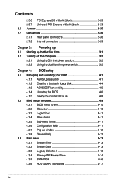
... flyers, that you need when installing and configuring the motherboard. Where to find more information Refer to change system settings through the BIOS Setup menus. ASUS websites The ASUS website provides updated information on the motherboard. • Chapter 3: Powering up This chapter describes the.... It includes description of the switches, jumpers, and connectors on ASUS hardware and software products. Detailed descriptions of the BIOS parameters are not part of shutting down the system. • Chapter 4: BIOS setup This chapter tells how to the following parts: • ...
... flyers, that you need when installing and configuring the motherboard. Where to find more information Refer to change system settings through the BIOS Setup menus. ASUS websites The ASUS website provides updated information on the motherboard. • Chapter 3: Powering up This chapter describes the.... It includes description of the switches, jumpers, and connectors on ASUS hardware and software products. Detailed descriptions of the BIOS parameters are not part of shutting down the system. • Chapter 4: BIOS setup This chapter tells how to the following parts: • ...
User Manual
Page 13
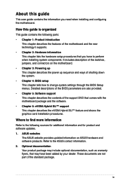
M3N72-D specifications summary Rear panel I/O ports 1 x PS/2 keyboard port (purple) 1 x S/PDIF Out (Coaxial) 1 x HDMI Out 1 x IEEE 1394a port 1 x LAN (RJ-45) 6 x USB 2.0/1.1 8-channel audio I/O Internal I/O connectors 3 ... 1 x CD audio in 1 x 24-pin ATX Power connector 1 x 4-pin ATX 12V Power connector 1 x System Panel (Q-Connector) BIOS features 8 Mb Flash ROM, Award BIOS, PnP, DMI 2.0, WfM2.0, SM BIOS 2.5, ACPI 2.0, ASUS EZ Flash 2 Support DVD contents Drivers Express Gate ASUS PC Probe II ASUS Update Anti-virus Utility (OEM version) Form factor ATX form factor: 12 in x 9.6 in (30...
M3N72-D specifications summary Rear panel I/O ports 1 x PS/2 keyboard port (purple) 1 x S/PDIF Out (Coaxial) 1 x HDMI Out 1 x IEEE 1394a port 1 x LAN (RJ-45) 6 x USB 2.0/1.1 8-channel audio I/O Internal I/O connectors 3 ... 1 x CD audio in 1 x 24-pin ATX Power connector 1 x 4-pin ATX 12V Power connector 1 x System Panel (Q-Connector) BIOS features 8 Mb Flash ROM, Award BIOS, PnP, DMI 2.0, WfM2.0, SM BIOS 2.5, ACPI 2.0, ASUS EZ Flash 2 Support DVD contents Drivers Express Gate ASUS PC Probe II ASUS Update Anti-virus Utility (OEM version) Form factor ATX form factor: 12 in x 9.6 in (30...
User Manual
Page 21
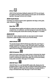
... easy to launch the utility and update the BIOS without entering the OS. Update your BIOS easily without the usual "fingers"- ASUS Q-Connector ASUS Q-Connector allows you easy ways to the motherboard. See page 2-41 for details. ASUS M3N72-D 1-5 ASUS EZ Flash 2 ASUS EZ Flash 2 is a user-friendly BIOS update utility. ASUS EZ DIY ASUS EZ DIY feature collection provides you to...
... easy to launch the utility and update the BIOS without entering the OS. Update your BIOS easily without the usual "fingers"- ASUS Q-Connector ASUS Q-Connector allows you easy ways to the motherboard. See page 2-41 for details. ASUS M3N72-D 1-5 ASUS EZ Flash 2 ASUS EZ Flash 2 is a user-friendly BIOS update utility. ASUS EZ DIY ASUS EZ DIY feature collection provides you to...

User Manual
Page 22
...parameter. 1-6 Chapter 1: Product Introduction C.P.R. (CPU Parameter Recall) The C.P.R. ASUS MyLogo 2™ This feature allows you can easily monitor the critical components of the motherboard BIOS allows automatic re-setting to the BIOS default settings in Windows environment without the hassle of booting the... BIOS. feature of the computer. When using ASUS PC Probe II, you to know which drivers...
...parameter. 1-6 Chapter 1: Product Introduction C.P.R. (CPU Parameter Recall) The C.P.R. ASUS MyLogo 2™ This feature allows you can easily monitor the critical components of the motherboard BIOS allows automatic re-setting to the BIOS default settings in Windows environment without the hassle of booting the... BIOS. feature of the computer. When using ASUS PC Probe II, you to know which drivers...
User Manual
Page 45
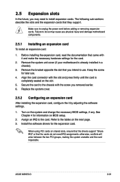
.... 2.5.2 Configuring an expansion card After installing the expansion card, configure the it and make the necessary hardware settings for information on BIOS setup. 2. otherwise, conflicts will arise between the two PCI groups, making the system unstable and the card inoperable. 2.5 Expansion ...you physical injury and damage motherboard components. 2.5.1 Installing an expansion card To install an expansion card: 1. Make sure to the card. The following sub‑sections describe the slots and the expansion cards that you removed earlier. 6. ASUS M3N72-D 2-21 Keep the screw...
.... 2.5.2 Configuring an expansion card After installing the expansion card, configure the it and make the necessary hardware settings for information on BIOS setup. 2. otherwise, conflicts will arise between the two PCI groups, making the system unstable and the card inoperable. 2.5 Expansion ...you physical injury and damage motherboard components. 2.5.1 Installing an expansion card To install an expansion card: 1. Make sure to the card. The following sub‑sections describe the slots and the expansion cards that you removed earlier. 6. ASUS M3N72-D 2-21 Keep the screw...
User Manual
Page 49
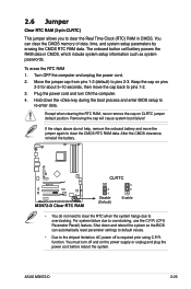
.... Turn OFF the computer and unplug the power cord. 2. Removing the cap will cause system boot failure! Hold down and reboot the system so the BIOS can clear the CMOS memory of date, time, and system setup parameters by erasing the CMOS RTC RAM data. If the steps above do not... 5~10 seconds, then move the jumper again to re-enter data. Shut down the key during the boot process and enter BIOS setup to clear the CMOS RTC RAM data. ASUS M3N72-D 2-25 Keep the cap on the power supply or unplug and plug the power cord before reboot the system. To erase...
.... Turn OFF the computer and unplug the power cord. 2. Removing the cap will cause system boot failure! Hold down and reboot the system so the BIOS can clear the CMOS memory of date, time, and system setup parameters by erasing the CMOS RTC RAM data. If the steps above do not... 5~10 seconds, then move the jumper again to re-enter data. Shut down the key during the boot process and enter BIOS setup to clear the CMOS RTC RAM data. ASUS M3N72-D 2-25 Keep the cap on the power supply or unplug and plug the power cord before reboot the system. To erase...
User Manual
Page 51
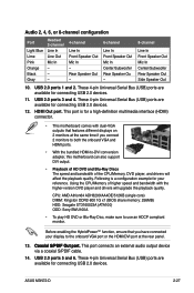
...This port is a configuration example for connecting USB 2.0 devices. 11. CPU: AMD Athlon64 ADH3200IAA4DE/512KB (single core) DIMM: Kingston DDR2-800 1G x1 (BIOS share memory: 256MB) HDD: Seagate ST3160023A (ATA100) ODD: Sony BWU100A • To play HD DVD or Blu-Ray Disc, make sure to -DVI... motherboard can also support DVI output. • Playback of HD DVD and Blu-Ray Discs The speed and bandwidth of higher speed and bandwidth with dual-VGA outputs that you have connected your reference. This port connects an external audio output device via a coaxial S/PDIF cable. 14. ASUS M3N72-D...
...This port is a configuration example for connecting USB 2.0 devices. 11. CPU: AMD Athlon64 ADH3200IAA4DE/512KB (single core) DIMM: Kingston DDR2-800 1G x1 (BIOS share memory: 256MB) HDD: Seagate ST3160023A (ATA100) ODD: Sony BWU100A • To play HD DVD or Blu-Ray Disc, make sure to -DVI... motherboard can also support DVI output. • Playback of HD DVD and Blu-Ray Discs The speed and bandwidth of higher speed and bandwidth with dual-VGA outputs that you have connected your reference. This port connects an external audio output device via a coaxial S/PDIF cable. 14. ASUS M3N72-D...
User Manual
Page 55
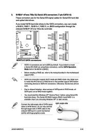
... SLI controller. • SATA1-4 connectors are set to install the AHCI driver or RAID driver in the motherboard support DVD. • SATA 5-6 connectors support AHCI mode and RAID mode only. right angle side ASUS M3N72-D 2-31 Make sure to [IDE] by default. 3. The Serial ATA RAID feature (RAID 0 and ... when set , refer to the manual bundled in the bundled support DVD before using these connectors, set the SATA Operation Mode item in the BIOS to [RAID]. • Before creating a RAID set any of SATA signal cable to SATA 5-6 connectors. If you install SATA hard disk ...
... SLI controller. • SATA1-4 connectors are set to install the AHCI driver or RAID driver in the motherboard support DVD. • SATA 5-6 connectors support AHCI mode and RAID mode only. right angle side ASUS M3N72-D 2-31 Make sure to [IDE] by default. 3. The Serial ATA RAID feature (RAID 0 and ... when set , refer to the manual bundled in the bundled support DVD before using these connectors, set the SATA Operation Mode item in the BIOS to [RAID]. • Before creating a RAID set any of SATA signal cable to SATA 5-6 connectors. If you install SATA hard disk ...
User Manual
Page 61
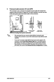
...ASUS M3N72-D 2-37 9. See section 4.4.6 Onboard Devices Configuration for a chassis-mounted front panel audio I /O module cable to [HD Audio]. Connect one end of the front panel audio I /O module that you connect a high-definition front panel audio module to this connector to avail of the motherboard's... high-definition audio capability. • If you want to connect a high-definition front panel audio module to this connector, set the Front Panel Support Type item in the BIOS setup to [AC97].
...ASUS M3N72-D 2-37 9. See section 4.4.6 Onboard Devices Configuration for a chassis-mounted front panel audio I /O module cable to [HD Audio]. Connect one end of the front panel audio I /O module that you connect a high-definition front panel audio module to this connector to avail of the motherboard's... high-definition audio capability. • If you want to connect a high-definition front panel audio module to this connector, set the Front Panel Support Type item in the BIOS setup to [AC97].
User Manual
Page 64
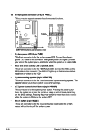
... to this connector. The system power LED lights up or flashes when data is read from or written to hear system beeps and warnings. • ATX power button/soft-off mode depending on or puts the system in sleep mode. • Hard disk drive activity LED (2-pin IDE_LED) This 2-pin connector...
... to this connector. The system power LED lights up or flashes when data is read from or written to hear system beeps and warnings. • ATX power button/soft-off mode depending on or puts the system in sleep mode. • Hard disk drive activity LED (2-pin IDE_LED) This 2-pin connector...
User Manual
Page 69
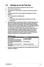
...failure 7. At power on self tests or POST. Follow the instructions in the following order: a. After making all switches are running, the BIOS beeps or additional messages appear on the chain) c. Be sure that is equipped with the last device on the screen. Connect the power ...cover. 2. If you do not see anything within 30 seconds from the time you press the ATX power button. Connect the power cord to the power connector at the back of the system chassis. 4. ASUS M3N72-D 3-1 External SCSI devices (starting with a surge protector. 5. Check the jumper settings and connections...
...failure 7. At power on self tests or POST. Follow the instructions in the following order: a. After making all switches are running, the BIOS beeps or additional messages appear on the chain) c. Be sure that is equipped with the last device on the screen. Connect the power ...cover. 2. If you do not see anything within 30 seconds from the time you press the ATX power button. Connect the power cord to the power connector at the back of the system chassis. 4. ASUS M3N72-D 3-1 External SCSI devices (starting with a surge protector. 5. Check the jumper settings and connections...
User Manual
Page 70
... While the system is ON, pressing the power switch for less than four seconds lets the system enter the soft-off mode regardless of the BIOS setting. Click the Start button then select ShutDown. 2. If you are using Windows® XP: 1. Refer to shut down the computer. 3. The power supply should... to section 4.5 Power Menu in Chapter 4 for more than four seconds puts the system to sleep mode or to soft-off mode, depending on the BIOS setting. Pressing the power switch for details. 3-2 Chapter 3: Powering up Click the Start button then select Turn Off Computer. 2.
... While the system is ON, pressing the power switch for less than four seconds lets the system enter the soft-off mode regardless of the BIOS setting. Click the Start button then select ShutDown. 2. If you are using Windows® XP: 1. Refer to shut down the computer. 3. The power supply should... to section 4.5 Power Menu in Chapter 4 for more than four seconds puts the system to sleep mode or to soft-off mode, depending on the BIOS setting. Pressing the power switch for details. 3-2 Chapter 3: Powering up Click the Start button then select Turn Off Computer. 2.
User Manual
Page 71
Detailed descriptions of the BIOS ChapBtIeOrS4:se4tup parameters are also provided. This chapter tells how to change the system settings through the BIOS Setup menus.
Detailed descriptions of the BIOS ChapBtIeOrS4:se4tup parameters are also provided. This chapter tells how to change the system settings through the BIOS Setup menus.
User Manual
Page 72
Chapter summary 4 4.1 Managing and updating your BIOS 4-1 4.2 BIOS setup program 4-9 4.3 Main menu 4-13 4.4 Advanced menu 4-18 4.5 Power menu 4-27 4.6 Boot menu 4-31 4.7 Tools menu 4-35 4.8 Exit menu 4-37 ASUS M3N72-D
Chapter summary 4 4.1 Managing and updating your BIOS 4-1 4.2 BIOS setup program 4-9 4.3 Main menu 4-13 4.4 Advanced menu 4-18 4.5 Power menu 4-27 4.6 Boot menu 4-31 4.7 Tools menu 4-35 4.8 Exit menu 4-37 ASUS M3N72-D
User Manual
Page 73
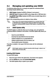
... following utilities allow you to manage, save, and update the motherboard BIOS in Windows® environment.) 2. Place the support DVD in the optical drive. The ASUS Update utility allows you to the corresponding sections for details on these utilities. ASUS M3N72-D 4-1 ASUS Update requires an Internet connection either through a network or an Internet Service Provider (ISP...
... following utilities allow you to manage, save, and update the motherboard BIOS in Windows® environment.) 2. Place the support DVD in the optical drive. The ASUS Update utility allows you to the corresponding sections for details on these utilities. ASUS M3N72-D 4-1 ASUS Update requires an Internet connection either through a network or an Internet Service Provider (ISP...


