User Manual
Page 25
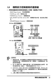
... PIN1 4 25 1.8 1 RESET(Reset Switch PLED(Power LED PWRSW(Power Switch IDE_LED(IDE Hard Disk Active LED SPEAKER(Speaker Connector 20-8 pin PLED SPEAKER 1 PANEL1 PLED+ PLED+5V Ground Ground Speaker P5B-E ® IDE_LED+ IDE_LED- PWR Ground Reset Ground 10-1 pin IDE_LED RESET PWRSW * Requires an ATX power supply. 紅色 1 表示 PIN1...
... PIN1 4 25 1.8 1 RESET(Reset Switch PLED(Power LED PWRSW(Power Switch IDE_LED(IDE Hard Disk Active LED SPEAKER(Speaker Connector 20-8 pin PLED SPEAKER 1 PANEL1 PLED+ PLED+5V Ground Ground Speaker P5B-E ® IDE_LED+ IDE_LED- PWR Ground Reset Ground 10-1 pin IDE_LED RESET PWRSW * Requires an ATX power supply. 紅色 1 表示 PIN1...

User Manual
Page 8
... area. If you are not sure about the voltage of the electrical outlet you are using, contact your local power company. • If the power supply is set to the correct voltage in your power supply is broken, do not try to fix it may become wet. • Place the product on it, carefully read... all cables are correctly connected and the power cables are not damaged. Do not place the product in municipal waste. Check local regulations for ...
... area. If you are not sure about the voltage of the electrical outlet you are using, contact your local power company. • If the power supply is set to the correct voltage in your power supply is broken, do not try to fix it may become wet. • Place the product on it, carefully read... all cables are correctly connected and the power cables are not damaged. Do not place the product in municipal waste. Check local regulations for ...

User Manual
Page 27
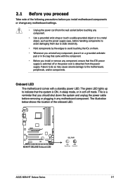
...shows the location of the following precautions before you install motherboard components or change any motherboard settings. • Unplug the power cord from the power supply. 2.1 Before you proceed Take note of the onboard LED. Onboard LED The motherboard comes with the component. •...the power cord is detached from the wall socket before touching any component. • Use a grounded wrist strap or touch a safely grounded object or to a metal object, such as the power supply case, before removing or plugging in the bag that came with a standby power LED. ASUS M3N-HT Deluxe ...
...shows the location of the following precautions before you install motherboard components or change any motherboard settings. • Unplug the power cord from the power supply. 2.1 Before you proceed Take note of the onboard LED. Onboard LED The motherboard comes with the component. •...the power cord is detached from the wall socket before touching any component. • Use a grounded wrist strap or touch a safely grounded object or to a metal object, such as the power supply case, before removing or plugging in the bag that came with a standby power LED. ASUS M3N-HT Deluxe ...
User Manual
Page 40
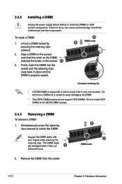
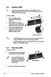
... sockets. 2.4.4 Removing a DIMM To remove a DIMM: 1. Remove the DIMM from the socket. 2 1 DIMM notch 2-14 Chapter 2: Hardware information To install a DIMM: 1. 2.4.3 Installing a DIMM Unplug the power supply before adding or removing DIMMs or other system components. Failure to do not support DDR DIMMs. DO not install DDR DIMMs to unlock the DIMM...
... sockets. 2.4.4 Removing a DIMM To remove a DIMM: 1. Remove the DIMM from the socket. 2 1 DIMM notch 2-14 Chapter 2: Hardware information To install a DIMM: 1. 2.4.3 Installing a DIMM Unplug the power supply before adding or removing DIMMs or other system components. Failure to do not support DDR DIMMs. DO not install DDR DIMMs to unlock the DIMM...
User Manual
Page 56
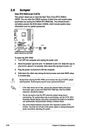
...pins 2-3 for about 5~10 seconds, then move the jumper again to clear the CMOS RTC RAM data. The onboard button cell battery powers the RAM data in CMOS. Plug the power cord and turn off is required to enable C.P.R. After the CMOS clearance, reinstall the battery. • You do not help, ... need to clear the RTC when the system hangs due to overclocking. To erase the RTC RAM: 1. Keep the cap on the power supply or unplug and plug the power cord before rebooting the system. 2-30 Chapter 2: Hardware information Shut down the key during the boot process and enter BIOS setup to...
...pins 2-3 for about 5~10 seconds, then move the jumper again to clear the CMOS RTC RAM data. The onboard button cell battery powers the RAM data in CMOS. Plug the power cord and turn off is required to enable C.P.R. After the CMOS clearance, reinstall the battery. • You do not help, ... need to clear the RTC when the system hangs due to overclocking. To erase the RTC RAM: 1. Keep the cap on the power supply or unplug and plug the power cord before rebooting the system. 2-30 Chapter 2: Hardware information Shut down the key during the boot process and enter BIOS setup to...
User Manual
Page 67
... the minimum power supply requirement for ATX power supply plugs. PSU suggested list PSU suggested list SilverStone ST1000 Seasonic SS-600HT Thermaltake W0083RE Thermaltake PUREPower-600AP Silverstone SST-ST75ZF EnerMAX EG701AX-VE (E)(24P) • If you are for your system, refer to use a power supply unit (PSU) that you use two or more power-consuming devices. 9. ASUS M3N-HT Deluxe Series...
... the minimum power supply requirement for ATX power supply plugs. PSU suggested list PSU suggested list SilverStone ST1000 Seasonic SS-600HT Thermaltake W0083RE Thermaltake PUREPower-600AP Silverstone SST-ST75ZF EnerMAX EG701AX-VE (E)(24P) • If you are for your system, refer to use a power supply unit (PSU) that you use two or more power-consuming devices. 9. ASUS M3N-HT Deluxe Series...

User Manual
Page 75
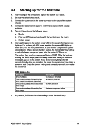
After making all switches are running, the BIOS beeps (see anything within 30 seconds from the time you press the ATX power button. ASUS M3N-HT Deluxe Series 3-1 3.1 Starting up for assistance. Be sure that is equipped with the last device on the devices in the following ...Check the jumper settings and connections or call your monitor complies with ATX power supplies, the system LED lights up when you turned on the power, the system may light up . Monitor b. System power 6. After applying power, the system power LED on , hold down the key to enter the BIOS Setup....
After making all switches are running, the BIOS beeps (see anything within 30 seconds from the time you press the ATX power button. ASUS M3N-HT Deluxe Series 3-1 3.1 Starting up for assistance. Be sure that is equipped with the last device on the devices in the following ...Check the jumper settings and connections or call your monitor complies with ATX power supplies, the system LED lights up when you turned on the power, the system may light up . Monitor b. System power 6. After applying power, the system power LED on , hold down the key to enter the BIOS Setup....
User Manual
Page 76
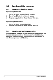
... turn off mode, depending on the BIOS setting. The power supply should turn off after Windows® shuts down. 3.2.2 Using the dual function power switch While the system is ON, pressing the power switch for more than four seconds puts the system to sleep mode or to shut down function If you... are using Windows® Vista™: 1. Click the Start button then select Shut Down. 2. Pressing the power switch for less than four seconds lets the system enter the soft-off the computer 3.2.1 Using the OS shut down the computer. 3. If you ...
... turn off mode, depending on the BIOS setting. The power supply should turn off after Windows® shuts down. 3.2.2 Using the dual function power switch While the system is ON, pressing the power switch for more than four seconds puts the system to sleep mode or to shut down function If you... are using Windows® Vista™: 1. Click the Start button then select Shut Down. 2. Pressing the power switch for less than four seconds lets the system enter the soft-off the computer 3.2.1 Using the OS shut down the computer. 3. If you ...
User Manual
Page 111
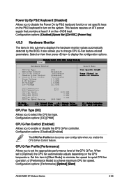
...65533;�ti�m��a��l]��[S��i�le��n�t�] ASUS M3N-HT Deluxe Series 4-33 Power Up By PS/2 Keyboard [Disabled] Allows you to disable the Power On by the BIOS. When set the appropriate performance level of the CPU Q-Fan. Configuration options: ... values automatically detected by PS/2 keyboard function or set specific keys on the +5VSB lead. This feature requires an ATX power supply that provides at least 1A on the PS/2 keyboard to enable or disable the CPU Q-Fan controller.
...65533;�ti�m��a��l]��[S��i�le��n�t�] ASUS M3N-HT Deluxe Series 4-33 Power Up By PS/2 Keyboard [Disabled] Allows you to disable the Power On by the BIOS. When set the appropriate performance level of the CPU Q-Fan. Configuration options: ... values automatically detected by PS/2 keyboard function or set specific keys on the +5VSB lead. This feature requires an ATX power supply that provides at least 1A on the PS/2 keyboard to enable or disable the CPU Q-Fan controller.
User Manual
Page 181
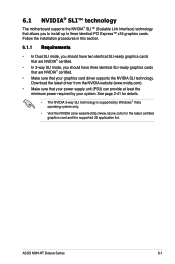
ASUS M3N-HT Deluxe Series 6-1 See page 2-41 for the latest certified graphics card and the supported 3D application list. Download the latest driver from the NVIDIA website (www.nvidia.com). • Make sure that your power supply unit (PSU) can provide at least the minimum power required by Windows® Vista operating system only. • Visit the...
ASUS M3N-HT Deluxe Series 6-1 See page 2-41 for the latest certified graphics card and the supported 3D application list. Download the latest driver from the NVIDIA website (www.nvidia.com). • Make sure that your power supply unit (PSU) can provide at least the minimum power required by Windows® Vista operating system only. • Visit the...
User Manual
Page 184
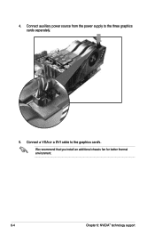
Connect a VGA or a DVI cable to the three graphics cards separately. 5. 4. Connect auxiliary power source from the power supply to the graphics card/s. We recommend that you install an additional chassis fan for better thermal environment. 6-4 Chapter 6: NVIDIA® technology support
Connect a VGA or a DVI cable to the three graphics cards separately. 5. 4. Connect auxiliary power source from the power supply to the graphics card/s. We recommend that you install an additional chassis fan for better thermal environment. 6-4 Chapter 6: NVIDIA® technology support
User Manual
Page 185
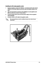
... is firmly in place. 3. ASUS M3N-HT Deluxe Series 6-5 Make sure that the cards are properly seated on each graphics card. Installing two SLI-ready graphics cards 1. Insert one graphics card into the PCIEX16_1 slot (blue) and the other into the PCIEX16_3 slot (blue). Connect auxiliary power source from the power supply to the two graphics cards...
... is firmly in place. 3. ASUS M3N-HT Deluxe Series 6-5 Make sure that the cards are properly seated on each graphics card. Installing two SLI-ready graphics cards 1. Insert one graphics card into the PCIEX16_1 slot (blue) and the other into the PCIEX16_3 slot (blue). Connect auxiliary power source from the power supply to the two graphics cards...
User Manual
Page 8
...problems with the package. • Before using the product, make sure all the manuals that the power cables for disposal of the crossed out wheeled bin indicates that your power supply is broken, do not try to the correct voltage in your area. This symbol of electronic products....system, ensure that came with the product, contact a qualified service technician or your local power company. • If the power supply is set to fix it , carefully read all cables are correctly connected and the power cables are not damaged. If you add a device. • Before connecting or ...
...problems with the package. • Before using the product, make sure all the manuals that the power cables for disposal of the crossed out wheeled bin indicates that your power supply is broken, do not try to the correct voltage in your area. This symbol of electronic products....system, ensure that came with the product, contact a qualified service technician or your local power company. • If the power supply is set to fix it , carefully read all cables are correctly connected and the power cables are not damaged. If you add a device. • Before connecting or ...
User Manual
Page 27
...a metal object, such as the power supply case, before removing or plugging in soft‑off or the power cord is ON, in sleep mode, or in any motherboard component. M3N-HT DELUXE M3N-HT DELUXE Onboard LED SB_PWR ON OFF Standy Power Powered Off ASUS M3N-HT Deluxe Series 2-1 Onboard LED The motherboard comes...you install motherboard components or change any motherboard settings. • Unplug the power cord from the power supply. Failure to do so may cause severe damage to indicate that the ATX power supply is switched off mode. The green LED lights up to the motherboard, ...
...a metal object, such as the power supply case, before removing or plugging in soft‑off or the power cord is ON, in sleep mode, or in any motherboard component. M3N-HT DELUXE M3N-HT DELUXE Onboard LED SB_PWR ON OFF Standy Power Powered Off ASUS M3N-HT Deluxe Series 2-1 Onboard LED The motherboard comes...you install motherboard components or change any motherboard settings. • Unplug the power cord from the power supply. Failure to do so may cause severe damage to indicate that the ATX power supply is switched off mode. The green LED lights up to the motherboard, ...
User Manual
Page 40
... it fits in only one direction. Support the DIMM lightly with extra force. 2. Align a DIMM on the socket. 1 3. To install a DIMM: 1. 2.4.3 Installing a DIMM Unplug the power supply before adding or removing DIMMs or other system components. Do not force a DIMM into the socket until the retaining clips snap back in place and...
... it fits in only one direction. Support the DIMM lightly with extra force. 2. Align a DIMM on the socket. 1 3. To install a DIMM: 1. 2.4.3 Installing a DIMM Unplug the power supply before adding or removing DIMMs or other system components. Do not force a DIMM into the socket until the retaining clips snap back in place and...
User Manual
Page 50
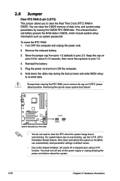
You can automatically reset parameter settings to default values. • Due to the chipset limitation, AC power off and on the power supply or unplug and plug the power cord before reboot the system. 2-24 Chapter 2: Hardware information Remove the onboard battery. 3. Move the jumper cap from pins 1-2 (... then move the cap back to pins 1-2. 4. M3N-HT DELUXE M3N-HT DELUXE Clear RTC RAM CLRTC 12 23 Disable (Default) Enable • You do not need to clear the RTC when the system hangs due to pins 2-3. function. Plug the power cord and turn off is required prior using C.P.R. Shut...
You can automatically reset parameter settings to default values. • Due to the chipset limitation, AC power off and on the power supply or unplug and plug the power cord before reboot the system. 2-24 Chapter 2: Hardware information Remove the onboard battery. 3. Move the jumper cap from pins 1-2 (... then move the cap back to pins 1-2. 4. M3N-HT DELUXE M3N-HT DELUXE Clear RTC RAM CLRTC 12 23 Disable (Default) Enable • You do not need to clear the RTC when the system hangs due to pins 2-3. function. Plug the power cord and turn off is required prior using C.P.R. Shut...
User Manual
Page 60
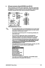
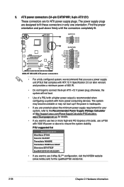
... of 600 W. • Do not forget to the Recommended Power Supply Wattage Calculator at http://support.asus.com/PowerSupplyCalculator/PSCalculator. aspx?SLanguage=en-us for your system, refer to connect the 8-pin ATX +12 V power plug; 9. The power supply plugs are designed to ensure the system stability. M3N-HT DELUXE EATX12V GND GND GND GND PIN 1 +12V DC +12V...
... of 600 W. • Do not forget to the Recommended Power Supply Wattage Calculator at http://support.asus.com/PowerSupplyCalculator/PSCalculator. aspx?SLanguage=en-us for your system, refer to connect the 8-pin ATX +12 V power plug; 9. The power supply plugs are designed to ensure the system stability. M3N-HT DELUXE EATX12V GND GND GND GND PIN 1 +12V DC +12V...
User Manual
Page 61
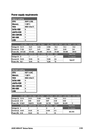
Power supply requirements Heavy Loading CPU SMF 3.2XE Memory 1 GB*4 VGA 8800 Ultra*3 SATA-HDD 6 eSATA-HDD 1 IDE-CDROM 1 IDE-HDD 1 USB 4 +12V_8Pin +12V_24pin +5V_24pin +3V_24pin +12V_VGA1 +12V_VGA2 +12V_VGA3 Voltage (V) 12.14 12.21 5.22 3.456 12.2 12.2 12.2 Current (A) 11.32 13.71 6.41 6.98 6.51 6.59 6.6 Power... Power (W) 81.824 108.913 32.500 23.736 79.544 83.204 0 SATA-HDD eSATA-HDD IDE-CDROM IDE-HDD USB Total PSU Voltage (V) 4 1 1 0 4 Po_max(w) Current (A) 10.45 10.45 10 Power (W) 41.8 10.45 10 12.68 2.5 0 10 481.970 ASUS M3N-HT Deluxe ...
Power supply requirements Heavy Loading CPU SMF 3.2XE Memory 1 GB*4 VGA 8800 Ultra*3 SATA-HDD 6 eSATA-HDD 1 IDE-CDROM 1 IDE-HDD 1 USB 4 +12V_8Pin +12V_24pin +5V_24pin +3V_24pin +12V_VGA1 +12V_VGA2 +12V_VGA3 Voltage (V) 12.14 12.21 5.22 3.456 12.2 12.2 12.2 Current (A) 11.32 13.71 6.41 6.98 6.51 6.59 6.6 Power... Power (W) 81.824 108.913 32.500 23.736 79.544 83.204 0 SATA-HDD eSATA-HDD IDE-CDROM IDE-HDD USB Total PSU Voltage (V) 4 1 1 0 4 Po_max(w) Current (A) 10.45 10.45 10 Power (W) 41.8 10.45 10 12.68 2.5 0 10 481.970 ASUS M3N-HT Deluxe ...
User Manual
Page 64
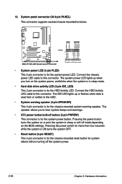
...reboot without turning off the system power. 2-38 Chapter 2: Hardware information The IDE LED lights up when you to this connector. PWR Ground Reset Ground M3N-HT DELUXE System panel connector IDE_LED PWRSW RESET * Requires an ATX power supply • System power LED (2-pin PLED) This 2-pin... connector is for the system power button. The speaker allows you turn on the BIOS ...
...reboot without turning off the system power. 2-38 Chapter 2: Hardware information The IDE LED lights up when you to this connector. PWR Ground Reset Ground M3N-HT DELUXE System panel connector IDE_LED PWRSW RESET * Requires an ATX power supply • System power LED (2-pin PLED) This 2-pin... connector is for the system power button. The speaker allows you turn on the BIOS ...
User Manual
Page 69
... for the first time 1. Check the jumper settings and connections or call your monitor complies with ATX power supplies, the system LED lights up when you press the ATX power button. ASUS M3N-HT Deluxe Series 3-1 3.1 Starting up for assistance. BIOS beep codes BIOS Beep One short beep One continuous beep...green after the system LED turns on the screen. For systems with "green" standards or if it has a "power standby" feature, the monitor LED may have failed a power-on the devices in the following order: a. After making all switches are running, the BIOS beeps (see anything ...
... for the first time 1. Check the jumper settings and connections or call your monitor complies with ATX power supplies, the system LED lights up when you press the ATX power button. ASUS M3N-HT Deluxe Series 3-1 3.1 Starting up for assistance. BIOS beep codes BIOS Beep One short beep One continuous beep...green after the system LED turns on the screen. For systems with "green" standards or if it has a "power standby" feature, the monitor LED may have failed a power-on the devices in the following order: a. After making all switches are running, the BIOS beeps (see anything ...


