User Guide
Page 3
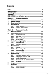
...vii Safety information viii About this guide ix Typography x KFSN4-DRE Series specifications summary xi Chapter 1: Product introduction 1.1 Welcome 1-1 1.2 Package contents 1-1 1.3 Serial number label 1-1 1.4 Special features 1-2 1.4.1 Product highlights 1-2 1.4.2 Innovative ASUS features 1-3 Chapter 2: Hardware information 2.1 Before you ...Installing a DIMM 2-15 2.4.4 Removing a DIMM 2-15 2.5 Expansion slots 2-16 2.5.1 Installing an expansion card 2-16 2.5.2 Configuring an expansion card 2-16 2.5.3 Interrupt assignments 2-17 2.5.4 PCI Express x16 slot (x8 link or x16 link 2-18...
...vii Safety information viii About this guide ix Typography x KFSN4-DRE Series specifications summary xi Chapter 1: Product introduction 1.1 Welcome 1-1 1.2 Package contents 1-1 1.3 Serial number label 1-1 1.4 Special features 1-2 1.4.1 Product highlights 1-2 1.4.2 Innovative ASUS features 1-3 Chapter 2: Hardware information 2.1 Before you ...Installing a DIMM 2-15 2.4.4 Removing a DIMM 2-15 2.5 Expansion slots 2-16 2.5.1 Installing an expansion card 2-16 2.5.2 Configuring an expansion card 2-16 2.5.3 Interrupt assignments 2-17 2.5.4 PCI Express x16 slot (x8 link or x16 link 2-18...

User Guide
Page 7
... following measures: • Reorient or relocate the receiving antenna. • Increase the separation between the equipment and receiver. • Connect the equipment to the graphics card is connected. • Consult the dealer or an experienced radio/TV technician for radio noise emissions from that interference will not occur in a residential installation...
... following measures: • Reorient or relocate the receiving antenna. • Increase the separation between the equipment and receiver. • Connect the equipment to the graphics card is connected. • Consult the dealer or an experienced radio/TV technician for radio noise emissions from that interference will not occur in a residential installation...

User Guide
Page 36
...2: Hardware information Turn on the next page. 3. Assign an IRQ to unplug the power cord before adding or removing expansion cards. Keep the screw for the expansion card. Install the software drivers for later use . 2.5 Expansion slots In the future, you may cause you physical injury and ... support "Share IRQ" or that they support. Make sure to the card. The following sub‑sections describe the slots and the expansion cards that the cards do so may need IRQ assignments. Secure the card to the tables on the system and change the necessary BIOS settings, if...
...2: Hardware information Turn on the next page. 3. Assign an IRQ to unplug the power cord before adding or removing expansion cards. Keep the screw for the expansion card. Install the software drivers for later use . 2.5 Expansion slots In the future, you may cause you physical injury and ... support "Share IRQ" or that they support. Make sure to the card. The following sub‑sections describe the slots and the expansion cards that the cards do so may need IRQ assignments. Secure the card to the tables on the system and change the necessary BIOS settings, if...
User Guide
Page 38
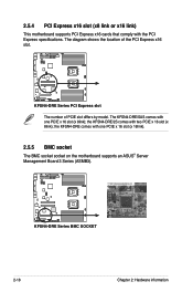
...2.5.5 BMC socket The BMC socket socket on the motherboard supports an ASUS® Server Management Board 3 Series (ASMB3). ® KFSN4-DRE Series BMC SOCKET 2-18 Chapter 2: Hardware information the KFSN4-DRE/2S comes with the PCI Express specifications. KFSN4-DRE Series PCI Express slot The number of the PCI Express x16 slot...® 2.5.4 PCI Express x16 slot (x8 link or x16 link) This motherboard supports PCI Express x16 cards that comply with two PCIE x 16 slot (x 8link); The KFSN4-DRE/SAS comes with one PCIE x 16 slot (x 8link); The diagram shows the location of PCIE slot differs ...
...2.5.5 BMC socket The BMC socket socket on the motherboard supports an ASUS® Server Management Board 3 Series (ASMB3). ® KFSN4-DRE Series BMC SOCKET 2-18 Chapter 2: Hardware information the KFSN4-DRE/2S comes with the PCI Express specifications. KFSN4-DRE Series PCI Express slot The number of the PCI Express x16 slot...® 2.5.4 PCI Express x16 slot (x8 link or x16 link) This motherboard supports PCI Express x16 cards that comply with two PCIE x 16 slot (x 8link); The KFSN4-DRE/SAS comes with one PCIE x 16 slot (x 8link); The diagram shows the location of PCIE slot differs ...

User Guide
Page 43
This RJ-45 port functions only when you install ASMB3/iKVM management card. 3. Serial (COM1) port. LAN 1 (RJ-45) port. 2.7 Connectors 2.7.1 Rear panel connectors 1 2 3 4 5 6 7 8 1. USB 2.0 ports 1 and 2....devices. 7. Refer to a Local Area Network (LAN) through a network hub. This port allows Gigabit connection to the table below for iKVM. This port is for the LAN port LED indications. 8. These two 4-pin Universal Serial Bus (USB) ports are available for a PS... 100 Mbps connection GREEN 1 Gbps connection ACT/LINK SPEED LED LED LAN port ASUS KFSN4-DRE Series 2-23
This RJ-45 port functions only when you install ASMB3/iKVM management card. 3. Serial (COM1) port. LAN 1 (RJ-45) port. 2.7 Connectors 2.7.1 Rear panel connectors 1 2 3 4 5 6 7 8 1. USB 2.0 ports 1 and 2....devices. 7. Refer to a Local Area Network (LAN) through a network hub. This port allows Gigabit connection to the table below for iKVM. This port is for the LAN port LED indications. 8. These two 4-pin Universal Serial Bus (USB) ports are available for a PS... 100 Mbps connection GREEN 1 Gbps connection ACT/LINK SPEED LED LED LAN port ASUS KFSN4-DRE Series 2-23
User Guide
Page 46
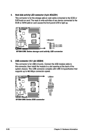
... activity LED connector (4-pin HDLED1) This connector is for the storage add-on card cable connected to the SCSI or SATA add-on card causes the front panel LED to light up to the SCSI or SATA add-on card. ADD_IN_CARD- USB connector (10-1 pin USB34) This connector is for USB 2.0 ports.... specification that supports up . ® ® HDLED1 PIN1 NC ADD_IN_CARD- USB34 Power USB PortB(-) USB PortB(+) GND NC Power USB PortA(-) USB PortA(+) GND PIN1 KFSN4-DRE Series USB connector 2-26 Chapter 2: Hardware information The read or write activities of the system chassis. NC...
... activity LED connector (4-pin HDLED1) This connector is for the storage add-on card cable connected to the SCSI or SATA add-on card causes the front panel LED to light up to the SCSI or SATA add-on card. ADD_IN_CARD- USB connector (10-1 pin USB34) This connector is for USB 2.0 ports.... specification that supports up . ® ® HDLED1 PIN1 NC ADD_IN_CARD- USB34 Power USB PortB(-) USB PortB(+) GND NC Power USB PortA(-) USB PortA(+) GND PIN1 KFSN4-DRE Series USB connector 2-26 Chapter 2: Hardware information The read or write activities of the system chassis. NC...

User Guide
Page 52
...the HDD Activity LED. POWERLED+ NC POWERLEDMLED+ MLEDNC +5V GND GND SPKROUT ® IDELED+ IDELEDNMIBTN# GND POWERBTN# GND NC RESETBTN# GND PANEL1 KFSN4-DRE Series System panel connector The system panel connector is installed, the read from or written to hear system beeps and warnings. • Power/Soft-off...If an optional SCSI or SATA add-in SLEEP or SOFT-OFF mode depending on the system power, and blinks when the system is in card causes this connector. Refer to this connector. Connect the HDD Activity LED cable to the connector description below for details. • System ...
...the HDD Activity LED. POWERLED+ NC POWERLEDMLED+ MLEDNC +5V GND GND SPKROUT ® IDELED+ IDELEDNMIBTN# GND POWERBTN# GND NC RESETBTN# GND PANEL1 KFSN4-DRE Series System panel connector The system panel connector is installed, the read from or written to hear system beeps and warnings. • Power/Soft-off...If an optional SCSI or SATA add-in SLEEP or SOFT-OFF mode depending on the system power, and blinks when the system is in card causes this connector. Refer to this connector. Connect the HDD Activity LED cable to the connector description below for details. • System ...

