
User Guide
Page 15
..., making it , check the items in the long line of the above items is damaged or missing, contact your retailer. ASUS KCMA-D8 1-3 Before you for the following items. Cables SATA data cable Standard Gift Box Pack Standard Bulk Pack 6 -- Optional items ...KVM over IP solution. Thank you start installing the motherboard, and hardware devices on it another standout in your motherboard package for buying an ASUS® KCMA-D8 motherboard! 1.1 Welcome! IO shield 1 1 Accessories Retension module 2 2 Application CD Support CD 1 1 Documentation User Guide 1 1 Packing...
..., making it , check the items in the long line of the above items is damaged or missing, contact your retailer. ASUS KCMA-D8 1-3 Before you for the following items. Cables SATA data cable Standard Gift Box Pack Standard Bulk Pack 6 -- Optional items ...KVM over IP solution. Thank you start installing the motherboard, and hardware devices on it another standout in your motherboard package for buying an ASUS® KCMA-D8 motherboard! 1.1 Welcome! IO shield 1 1 Accessories Retension module 2 2 Application CD Support CD 1 1 Documentation User Guide 1 1 Packing...

User Guide
Page 17
... requirements. Serial ATA allows thinner, more flexible cables with dual Gigabit LAN controllers and ports which makes it an ideal memory solution. ASUS KCMA-D8 1-5 USB 2.0 is monitored for your networking needs. The Serial ATA II specification provides twice the bandwidth of the current Serial ATA... increasing the connection speed from 1.8 V for DDR2 to just 1.5V for twice the current speed and bandwidth. DDR3 memory support The KCMA-D8 supports UDIMM and RDIMM DDR3 memory that features data transfer rates of 1333/1066/800 MHz to meet the higher bandwidth requirements of new ...
... requirements. Serial ATA allows thinner, more flexible cables with dual Gigabit LAN controllers and ports which makes it an ideal memory solution. ASUS KCMA-D8 1-5 USB 2.0 is monitored for your networking needs. The Serial ATA II specification provides twice the bandwidth of the current Serial ATA... increasing the connection speed from 1.8 V for DDR2 to just 1.5V for twice the current speed and bandwidth. DDR3 memory support The KCMA-D8 supports UDIMM and RDIMM DDR3 memory that features data transfer rates of 1333/1066/800 MHz to meet the higher bandwidth requirements of new ...

User Guide
Page 20
Chapter summary 2 2.1 Before you proceed 2-3 2.2 Motherboard overview 2-6 2.3 Central Processing Unit (CPU 2-10 2.4 System memory 2-18 2.5 Expansion slots 2-21 2.6 Jumpers 2-27 2.7 Connectors 2-31 ASUS KCMA-D8
Chapter summary 2 2.1 Before you proceed 2-3 2.2 Motherboard overview 2-6 2.3 Central Processing Unit (CPU 2-10 2.4 System memory 2-18 2.5 Expansion slots 2-21 2.6 Jumpers 2-27 2.7 Connectors 2-31 ASUS KCMA-D8

User Guide
Page 21
... is switched off mode. The green LED lights up to the motherboard, peripherals, and/or components. 2.1 Before you proceed Take note of the onboard LED ASUS KCMA-D8 2-3 Failure to do so may cause severe damage to indicate that you should shut down the system and unplug the power cable before removing or...
... is switched off mode. The green LED lights up to the motherboard, peripherals, and/or components. 2.1 Before you proceed Take note of the onboard LED ASUS KCMA-D8 2-3 Failure to do so may cause severe damage to indicate that you should shut down the system and unplug the power cable before removing or...

User Guide
Page 23
ASUS KCMA-D8 2-5 BMC LED (BMC_LED1) The green heartbeat LED blinks per second to indicate that the ASMB4 is working normally. The heartbeat LED functions only when you install the ASUS ASMB4. 4.
ASUS KCMA-D8 2-5 BMC LED (BMC_LED1) The green heartbeat LED blinks per second to indicate that the ASMB4 is working normally. The heartbeat LED functions only when you install the ASUS ASMB4. 4.

User Guide
Page 25
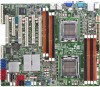
2.2.3 Motherboard layouts ASUS KCMA-D8 2-7
2.2.3 Motherboard layouts ASUS KCMA-D8 2-7

User Guide
Page 29
... 3 6. Press the load lever with your thumb (A), then move it to the socket pins, do not remove the PnP cap unless you are installing a CPU. ASUS KCMA-D8 Gold triangle mark Alignment keys 2-11
... 3 6. Press the load lever with your thumb (A), then move it to the socket pins, do not remove the PnP cap unless you are installing a CPU. ASUS KCMA-D8 Gold triangle mark Alignment keys 2-11

User Guide
Page 31
2.3.2 Installing the retension module base You may need to install the retension module base on the screw stand. 3. Repeat steps 2 to 3 to install the other retension module to the motherboard. 4. To install the retension module base: 1. Use the screw that comes with the retension module to secure the retension module to the motherboard. Place one retension module on the motherboard before installing a CPU heatsink and fan assembly. Locate the two screw stands beside the CPU socket. 2. ASUS KCMA-D8 2-13
2.3.2 Installing the retension module base You may need to install the retension module base on the screw stand. 3. Repeat steps 2 to 3 to install the other retension module to the motherboard. 4. To install the retension module base: 1. Use the screw that comes with the retension module to secure the retension module to the motherboard. Place one retension module on the motherboard before installing a CPU heatsink and fan assembly. Locate the two screw stands beside the CPU socket. 2. ASUS KCMA-D8 2-13

User Guide
Page 33
Ensure that the retention bracket is in place. 4. A clicking sound denotes that the heatsink and fan assembly perfectly fits the retention mechanism module base, otherwise you cannot snap the retention bracket in place. Push down the retention bracket lock on the retention mechanism to secure the heatsink and fan assembly to the retention module base. 3. ASUS KCMA-D8 2-15 Attach one end of the retention bracket to the retention module base. 2. Align the other end of the retention bracket to the module base.
Ensure that the retention bracket is in place. 4. A clicking sound denotes that the heatsink and fan assembly perfectly fits the retention mechanism module base, otherwise you cannot snap the retention bracket in place. Push down the retention bracket lock on the retention mechanism to secure the heatsink and fan assembly to the retention module base. 3. ASUS KCMA-D8 2-15 Attach one end of the retention bracket to the retention module base. 2. Align the other end of the retention bracket to the module base.

User Guide
Page 35
When the two screws are attached, tighten them one by one to the motherboard. To install the CPU heatsink: 1. Place the heatsink on top of the CPU heatsink and fan assembly. Twist each of the two screws with a Philips (cross) screwdriver just enough to attach the heatsink to completely secure the heatsink. 2.3.4 Installing the CPU heatsink You may want to install your optional CPU heatsink instead of the installed CPU, ensuring that the two fasteners match the screw stands on the motherboard. 3. Locate the two screw stands beside the CPU socket. 2. ASUS KCMA-D8 2-17
When the two screws are attached, tighten them one by one to the motherboard. To install the CPU heatsink: 1. Place the heatsink on top of the CPU heatsink and fan assembly. Twist each of the two screws with a Philips (cross) screwdriver just enough to attach the heatsink to completely secure the heatsink. 2.3.4 Installing the CPU heatsink You may want to install your optional CPU heatsink instead of the installed CPU, ensuring that the two fasteners match the screw stands on the motherboard. 3. Locate the two screw stands beside the CPU socket. 2. ASUS KCMA-D8 2-17

User Guide
Page 37
..., Dual Ranks) & RDIMM (Single Rank, Dual Ranks & Quad Ranks) CPU1 Configuration DIMM_A2 2 DIMMs V 4 DIMMs V DIMM_A1 V DIMM_B2 V V DIMM_B1 V CPU2 Configuration DIMM_C2 2 DIMMs V 4 DIMMs V DIMM_C1 V DIMM_D2 V V DIMM_D1 V ASUS KCMA-D8 2-19 For optimum compatibility, it is recommended that you obtain memory modules from the same vendor. • For CPU1 configuraton, install DIMMs from the orange...
..., Dual Ranks) & RDIMM (Single Rank, Dual Ranks & Quad Ranks) CPU1 Configuration DIMM_A2 2 DIMMs V 4 DIMMs V DIMM_A1 V DIMM_B2 V V DIMM_B1 V CPU2 Configuration DIMM_C2 2 DIMMs V 4 DIMMs V DIMM_C1 V DIMM_D2 V V DIMM_D1 V ASUS KCMA-D8 2-19 For optimum compatibility, it is recommended that you obtain memory modules from the same vendor. • For CPU1 configuraton, install DIMMs from the orange...

User Guide
Page 39
... install an expansion card: 1. Remove the system unit cover (if your motherboard is completely seated on the slot. 5. Secure the card to install expansion cards. ASUS KCMA-D8 2-21 Failure to the card. Keep the screw for the card. 2. Assign an IRQ to do not need to the chassis with the screw you...
... install an expansion card: 1. Remove the system unit cover (if your motherboard is completely seated on the slot. 5. Secure the card to install expansion cards. ASUS KCMA-D8 2-21 Failure to the card. Keep the screw for the card. 2. Assign an IRQ to do not need to the chassis with the screw you...

User Guide
Page 41
... x4 link) (Auto turn off if PIKE slot is occupied, MIO supported) PCI slot PIKE Interface The PIKE Interface is for ASUS PIKE RAID card only. ASUS KCMA-D8 2-23 Install an optional ASUS PIKE RAID card based on cards. 2.5.5 PCI Express x8 slot (x4 link) The onboard PCI Express x8 slot supports cards that...
... x4 link) (Auto turn off if PIKE slot is occupied, MIO supported) PCI slot PIKE Interface The PIKE Interface is for ASUS PIKE RAID card only. ASUS KCMA-D8 2-23 Install an optional ASUS PIKE RAID card based on cards. 2.5.5 PCI Express x8 slot (x4 link) The onboard PCI Express x8 slot supports cards that...

User Guide
Page 43
Orient and press the ASMB4 management card in place. ASUS KCMA-D8 2-25 You need to install I Button before using PIKE 1078 functions. 2.5.10 Installing ASMB4 management card Follow the steps below to install an optional ASMB4 management card on the motherboard. 2. Locate the i Button slot on your motherboard. 1. Snap the i Button in place. 2.5.9 Installing i Button Follow the steps below to install an optional i Button on the motherboard. 2. Locate the BMC_FW header on your motherboard. 1.
Orient and press the ASMB4 management card in place. ASUS KCMA-D8 2-25 You need to install I Button before using PIKE 1078 functions. 2.5.10 Installing ASMB4 management card Follow the steps below to install an optional ASMB4 management card on the motherboard. 2. Locate the i Button slot on your motherboard. 1. Snap the i Button in place. 2.5.9 Installing i Button Follow the steps below to install an optional i Button on the motherboard. 2. Locate the BMC_FW header on your motherboard. 1.

User Guide
Page 45
To erase the RTC RAM: 1. Keep the cap on CLRTC jumper default position. ASUS KCMA-D8 2-27 Turn OFF the computer and unplug the power cord. 2. 2.6 Jumpers 1. You can clear the CMOS memory of date, time, and system setup parameters by ...
To erase the RTC RAM: 1. Keep the cap on CLRTC jumper default position. ASUS KCMA-D8 2-27 Turn OFF the computer and unplug the power cord. 2. 2.6 Jumpers 1. You can clear the CMOS memory of date, time, and system setup parameters by ...

User Guide
Page 47
PIKE slot setting (3-pin PIKE_SW1) The slot 2 and PIKE slot share the x4 link. LVDDR3_SEL2) These jumpers allow you can place the jumper cap on pins 2-3 to assign the x4 link to let the system swtich the assignment automatically depending on pins 1-2 to the PIKE slot. Set to pins 1-2 to select 1.5V BIOS control, pins 2-3 to select 1.2V Force or 3-4 to adjust the DIMM voltage. 4. Or you to select 1.35V Force. 5. Place the jumper cap on which slot is occupied. DDR3 voltage control setting (4-pin LVDDR3_SEL1; ASUS KCMA-D8 2-29
PIKE slot setting (3-pin PIKE_SW1) The slot 2 and PIKE slot share the x4 link. LVDDR3_SEL2) These jumpers allow you can place the jumper cap on pins 2-3 to assign the x4 link to let the system swtich the assignment automatically depending on pins 1-2 to the PIKE slot. Set to pins 1-2 to select 1.5V BIOS control, pins 2-3 to select 1.2V Force or 3-4 to adjust the DIMM voltage. 4. Or you to select 1.35V Force. 5. Place the jumper cap on which slot is occupied. DDR3 voltage control setting (4-pin LVDDR3_SEL1; ASUS KCMA-D8 2-29

User Guide
Page 49
... BLINKING Data activity Speed LED Status Description OFF 10 Mbps connection ORANGE 100 Mbps connection GREEN 1 Gbps connection ACT/LINK SPEED LED LED LAN port ASUS KCMA-D8 2-31
... BLINKING Data activity Speed LED Status Description OFF 10 Mbps connection ORANGE 100 Mbps connection GREEN 1 Gbps connection ACT/LINK SPEED LED LED LAN port ASUS KCMA-D8 2-31

User Guide
Page 51
SAS connectors (7-pin SAS1, SAS2, SAS3, SAS4; Blue) This motherboard comes with eight (8) Serial Attached SCSI (SAS) connectors, the next-generation storage technology that supports both Serial Attached SCSI (SAS) and Serial ATA (SATA). Each connector supports one device. • These connectors function only when you install a PIKE RAID card. • Connect the SAS hard disk drives to SAS connectors 1-4 (red) when installing a 4-port PIKE RAID card. 2. Red) (7-pin SAS5, SAS6, SAS7, SAS8; ASUS KCMA-D8 2-33
SAS connectors (7-pin SAS1, SAS2, SAS3, SAS4; Blue) This motherboard comes with eight (8) Serial Attached SCSI (SAS) connectors, the next-generation storage technology that supports both Serial Attached SCSI (SAS) and Serial ATA (SATA). Each connector supports one device. • These connectors function only when you install a PIKE RAID card. • Connect the SAS hard disk drives to SAS connectors 1-4 (red) when installing a 4-port PIKE RAID card. 2. Red) (7-pin SAS5, SAS6, SAS7, SAS8; ASUS KCMA-D8 2-33

User Guide
Page 53
... jumper caps on the motherboard, ensuring that the black wire of each cable matches the ground pin of 3.15 A-6.66 A (53.28 W max.) at +12V. 5. ASUS KCMA-D8 2-35 CPU, front and rear fan connectors (4-pin CPU_FAN1, CPU_FAN2, FRNT_FAN1, FRNT_FAN2, FRNT_FAN3, FRNT_FAN4, FRNT_FAN5, REAR_FAN1) The fan connectors support cooling fans of 350 mA... of the connector. • DO NOT forget to connect the fan cables to the fan connectors on the fan connectors! • All fans feature the ASUS Fan Speed technology.
... jumper caps on the motherboard, ensuring that the black wire of each cable matches the ground pin of 3.15 A-6.66 A (53.28 W max.) at +12V. 5. ASUS KCMA-D8 2-35 CPU, front and rear fan connectors (4-pin CPU_FAN1, CPU_FAN2, FRNT_FAN1, FRNT_FAN2, FRNT_FAN3, FRNT_FAN4, FRNT_FAN5, REAR_FAN1) The fan connectors support cooling fans of 350 mA... of the connector. • DO NOT forget to connect the fan cables to the fan connectors on the fan connectors! • All fans feature the ASUS Fan Speed technology.

User Guide
Page 55
BMC header (BMC_FW1) The BMC connector on the motherboard supports an ASUS® Server Management Board 4 Series (ASMB4). ASUS KCMA-D8 2-37 Connect the serial port module cable to this connector, then install the module to the slot opening at the back of the system chassis. The serial port module is for the serial (COM) port. Serial port connector (10-1 pin COM2) This connector is purchased separately. 9. 8.
BMC header (BMC_FW1) The BMC connector on the motherboard supports an ASUS® Server Management Board 4 Series (ASMB4). ASUS KCMA-D8 2-37 Connect the serial port module cable to this connector, then install the module to the slot opening at the back of the system chassis. The serial port module is for the serial (COM) port. Serial port connector (10-1 pin COM2) This connector is purchased separately. 9. 8.


