K8N-E Deluxe User's Manual
Page 15
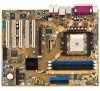
Supporting up to set a new benchmark for buying the ASUS® K8N-E Deluxe motherboard! The motherboard delivers a host of the above items is damaged or missing, contact your package with PC3200/PC2700/PC2100/ PC1600 DDR SDRAM, high-resolution graphics via ...new features and latest technologies making it , check the items in the long line of power computing! Thank you ahead in the world of ASUS quality motherboards! Before you start installing the motherboard, and hardware devices on it another standout in your retailer. ASUS K8N-E Deluxe motherboard 1-1 1.1 Welcome!
Supporting up to set a new benchmark for buying the ASUS® K8N-E Deluxe motherboard! The motherboard delivers a host of the above items is damaged or missing, contact your package with PC3200/PC2700/PC2100/ PC1600 DDR SDRAM, high-resolution graphics via ...new features and latest technologies making it , check the items in the long line of power computing! Thank you ahead in the world of ASUS quality motherboards! Before you start installing the motherboard, and hardware devices on it another standout in your retailer. ASUS K8N-E Deluxe motherboard 1-1 1.1 Welcome!
K8N-E Deluxe User's Manual
Page 17
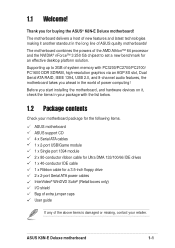
...2.0 is the VGA interface specification that works with the Marvell® Gigabit LAN PHY to provide a solution for LAN on Motherboard (LOM) applications. The IEEE 1394 interface allows up to 400Mbps transfer rates through simple, low-cost, high-bandwidth asynchronous (real...250Gb chipset comes with a built-in LAN controller that enables enhanced graphics performance with maximum bandwidth speed of up to 2.12 GB/s. ASUS K8N-E Deluxe motherboard 1-3 AGP 8X support AGP 8X (AGP 3.0) is backward compatible with digital connectivity to powerful speaker systems. IEEE 1394 support The IEEE ...
...2.0 is the VGA interface specification that works with the Marvell® Gigabit LAN PHY to provide a solution for LAN on Motherboard (LOM) applications. The IEEE 1394 interface allows up to 400Mbps transfer rates through simple, low-cost, high-bandwidth asynchronous (real...250Gb chipset comes with a built-in LAN controller that enables enhanced graphics performance with maximum bandwidth speed of up to 2.12 GB/s. ASUS K8N-E Deluxe motherboard 1-3 AGP 8X support AGP 8X (AGP 3.0) is backward compatible with digital connectivity to powerful speaker systems. IEEE 1394 support The IEEE ...

K8N-E Deluxe User's Manual
Page 19
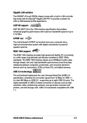
... without booting the system to configure easier and faster. ASUS Multi-language BIOS The multi-language BIOS allows you to Windows™. The localized BIOS menus allow you to select the language of the motherboard BIOS allows automatic re-setting to the BIOS default settings... reboot the system to use a DOS-based utility or boot from the available options. See page 4-4. Just press the ASUS Instant Music special function keys and enjoy the music! ASUS K8N-E Deluxe motherboard 1-5 No need to overclocking, C.P.R. See pages 4-15, 5-11. C.P.R. (CPU Parameter Recall) The C.P.R.
... without booting the system to configure easier and faster. ASUS Multi-language BIOS The multi-language BIOS allows you to Windows™. The localized BIOS menus allow you to select the language of the motherboard BIOS allows automatic re-setting to the BIOS default settings... reboot the system to use a DOS-based utility or boot from the available options. See page 4-4. Just press the ASUS Instant Music special function keys and enjoy the music! ASUS K8N-E Deluxe motherboard 1-5 No need to overclocking, C.P.R. See pages 4-15, 5-11. C.P.R. (CPU Parameter Recall) The C.P.R.

K8N-E Deluxe User's Manual
Page 22
Chapter summary 2.1 Before you proceed 2-1 2.2 Motherboard overview 2-2 2.3 Central Processing Unit (CPU 2-6 2.4 System memory 2-11 2.5 Expansion slots 2-14 2.6 Jumpers 2-18 2.7 Connectors 2-20 ASUS K8N-E Deluxe motherboard
Chapter summary 2.1 Before you proceed 2-1 2.2 Motherboard overview 2-2 2.3 Central Processing Unit (CPU 2-6 2.4 System memory 2-11 2.5 Expansion slots 2-14 2.6 Jumpers 2-18 2.7 Connectors 2-20 ASUS K8N-E Deluxe motherboard

K8N-E Deluxe User's Manual
Page 23
... any component, ensure that you proceed Note of the onboard LED. ® K8N-E K8N-E Onboard LED SB_PWR ON Standby Power OFF Powered Off ASUS K8N-E Deluxe motherboard 2-1 The illustration below shows the location of the following precautions before you install motherboard components or change any motherboard settings. • Unplug the power cord from the power supply. Onboard LED...
... any component, ensure that you proceed Note of the onboard LED. ® K8N-E K8N-E Onboard LED SB_PWR ON Standby Power OFF Powered Off ASUS K8N-E Deluxe motherboard 2-1 The illustration below shows the location of the following precautions before you install motherboard components or change any motherboard settings. • Unplug the power cord from the power supply. Onboard LED...
K8N-E Deluxe User's Manual
Page 25
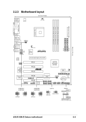
...Speaker PANEL Speaker Power LED Connector Reset SW ATX Power IDE_LED Switch* * Requires an ATX power supply. ASUS K8N-E Deluxe motherboard 2-3 PRI_IDE SEC_IDE 30.5cm (12.0in) 2.2.3 Motherboard layout 24.5cm (9.6in) PS/2KBMS T: Mouse B: Keyboard SPDIF_O1 ATX12V CPU_FAN SPDIF_O2 ATX Power Connector DDR... Accelerated Graphics Port (AGP) PCI1 PCI2 ® PCI3 nVIDIA nForce3 250Gb 4Mbit BIOS CHA_FAN Super I/O COM2 PCI4 K8N-E PCI5 GAME Speech Controller Silicon Image SATA Controller SATA_RAID1 SATA_RAID3 SATA_RAID2 SATA_RAID4 USBPW56 USBPW78 FLOPPY CR2032 3V SB_PWR Lithium Cell...
...Speaker PANEL Speaker Power LED Connector Reset SW ATX Power IDE_LED Switch* * Requires an ATX power supply. ASUS K8N-E Deluxe motherboard 2-3 PRI_IDE SEC_IDE 30.5cm (12.0in) 2.2.3 Motherboard layout 24.5cm (9.6in) PS/2KBMS T: Mouse B: Keyboard SPDIF_O1 ATX12V CPU_FAN SPDIF_O2 ATX Power Connector DDR... Accelerated Graphics Port (AGP) PCI1 PCI2 ® PCI3 nVIDIA nForce3 250Gb 4Mbit BIOS CHA_FAN Super I/O COM2 PCI4 K8N-E PCI5 GAME Speech Controller Silicon Image SATA Controller SATA_RAID1 SATA_RAID3 SATA_RAID2 SATA_RAID4 USBPW56 USBPW78 FLOPPY CR2032 3V SB_PWR Lithium Cell...
K8N-E Deluxe User's Manual
Page 27
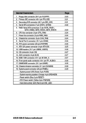
... activity LED (Red 2-pin IDE_LED) Page 2-20 2-21 2-21 2-22 2-23 2-24 2-24 2-24 2-24 2-25 2-25 2-26 2-27 2-27 2-27 2-28 2-28 2-29 2-29 ASUS K8N-E Deluxe motherboard 2-5 Internal Connectors 1. IEEE 1394 connector (10-1 pin IE1394_1) 16. Front panel audio connector (10-1 pin FP_AUDIO) 17. Serial ATA connectors (7-pin SATA1, SATA2) 5. Chassis fan...
... activity LED (Red 2-pin IDE_LED) Page 2-20 2-21 2-21 2-22 2-23 2-24 2-24 2-24 2-24 2-25 2-25 2-26 2-27 2-27 2-27 2-28 2-28 2-29 2-29 ASUS K8N-E Deluxe motherboard 2-5 Internal Connectors 1. IEEE 1394 connector (10-1 pin IE1394_1) 16. Front panel audio connector (10-1 pin FP_AUDIO) 17. Serial ATA connectors (7-pin SATA1, SATA2) 5. Chassis fan...

K8N-E Deluxe User's Manual
Page 29
... lift it up to indicate that it fits in one correct orientation. 2. The lever clicks on the side tab to a 90°-100° angle. ASUS K8N-E Deluxe motherboard 2-7 Position the CPU above the socket such that the socket lever is locked. Small triangle Gold triangle The CPU fits only in place. Socket Lever...
... lift it up to indicate that it fits in one correct orientation. 2. The lever clicks on the side tab to a 90°-100° angle. ASUS K8N-E Deluxe motherboard 2-7 Position the CPU above the socket such that the socket lever is locked. Small triangle Gold triangle The CPU fits only in place. Socket Lever...

K8N-E Deluxe User's Manual
Page 31
Align the other end of the retention bracket to the retention module base. Make sure that the retention bracket is in place. 4. 2. A clicking sound denotes that the fan and heatsink assembly perfectly fits the retention mechanism module base, otherwise you cannot snap the retention bracket in place. Attach one end of the retention bracket (near the retention bracket lock) to the retention module base. 3. Push down the retention bracket lock on the retention mechanism to secure the heatsink and fan to the module base. ASUS K8N-E Deluxe motherboard 2-9
Align the other end of the retention bracket to the retention module base. Make sure that the retention bracket is in place. 4. 2. A clicking sound denotes that the fan and heatsink assembly perfectly fits the retention mechanism module base, otherwise you cannot snap the retention bracket in place. Attach one end of the retention bracket (near the retention bracket lock) to the retention module base. 3. Push down the retention bracket lock on the retention mechanism to secure the heatsink and fan to the module base. ASUS K8N-E Deluxe motherboard 2-9

K8N-E Deluxe User's Manual
Page 33
...configurations in Table 1. • For optimum compatibility, obtain memory modules from the same vendors. Important notes on page 2-13. ASUS K8N-E Deluxe motherboard 2-11 The following figure illustrates the location of the memory configurations in this section. DIMM1 DIMM2 DIMM3 104 Pins 80 Pins ® ...K8V-E K8N-E 184-Pin DDR DIMM Sockets 2.4.2 Memory configurations You may cause memory sizing error or system boot failure. For optimum compatibility,...
...configurations in Table 1. • For optimum compatibility, obtain memory modules from the same vendors. Important notes on page 2-13. ASUS K8N-E Deluxe motherboard 2-11 The following figure illustrates the location of the memory configurations in this section. DIMM1 DIMM2 DIMM3 104 Pins 80 Pins ® ...K8V-E K8N-E 184-Pin DDR DIMM Sockets 2.4.2 Memory configurations You may cause memory sizing error or system boot failure. For optimum compatibility,...

K8N-E Deluxe User's Manual
Page 35
... your fingers when pressing the retaining clips. Locked Retaining Clip 2.4.4 Removing a DIMM Follow these steps to unlock the DIMM. Remove the DIMM from the socket. ASUS K8N-E Deluxe motherboard 2-13 Unlock a DIMM socket by pressing the retaining clips outward. 2. Failure to do so may cause severe damage to unplug the power supply before adding...
... your fingers when pressing the retaining clips. Locked Retaining Clip 2.4.4 Removing a DIMM Follow these steps to unlock the DIMM. Remove the DIMM from the socket. ASUS K8N-E Deluxe motherboard 2-13 Unlock a DIMM socket by pressing the retaining clips outward. 2. Failure to do so may cause severe damage to unplug the power supply before adding...
K8N-E Deluxe User's Manual
Page 37
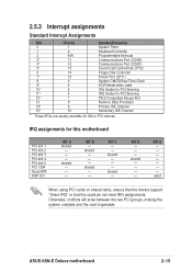
...shared slots, ensure that the drivers support "Share IRQ" or that the cards do not need IRQ assignments. shared - - shared - - - shared - shared - - - ASUS K8N-E Deluxe motherboard 2-15 INT C - - shared - - - - shared - - - IRQ assignments for ISA or PCI devices. INT B - INT E used 10* 5 IRQ Holder ... Mouse Port 13 8 Numeric Data Processor 14* 9 Primary IDE Channel 15* 10 Secondary IDE Channel * These IRQs are usually available for this motherboard PCI slot 1 PCI slot 2 PCI slot 3 PCI slot 4 PCI slot 5 PCI 1394 Serial ATA AGP slot INT A shared - - ...
...shared slots, ensure that the drivers support "Share IRQ" or that the cards do not need IRQ assignments. shared - - shared - - - shared - shared - - - ASUS K8N-E Deluxe motherboard 2-15 INT C - - shared - - - - shared - - - IRQ assignments for ISA or PCI devices. INT B - INT E used 10* 5 IRQ Holder ... Mouse Port 13 8 Numeric Data Processor 14* 9 Primary IDE Channel 15* 10 Secondary IDE Channel * These IRQs are usually available for this motherboard PCI slot 1 PCI slot 2 PCI slot 3 PCI slot 4 PCI slot 5 PCI 1394 Serial ATA AGP slot INT A shared - - ...

K8N-E Deluxe User's Manual
Page 39
... about 5~10 seconds, then move the cap back to clear the Real Time Clock (RTC) RAM in data. ® K8V-E K8N-E Clear RTC RAM CLRTC 12 23 Normal (Default) Clear CMOS ASUS K8N-E Deluxe motherboard 2-17 Load the BIOS default settings or key-in CMOS. Hold down the key during the boot process and enter...
... about 5~10 seconds, then move the cap back to clear the Real Time Clock (RTC) RAM in data. ® K8V-E K8N-E Clear RTC RAM CLRTC 12 23 Normal (Default) Clear CMOS ASUS K8N-E Deluxe motherboard 2-17 Load the BIOS default settings or key-in CMOS. Hold down the key during the boot process and enter...
K8N-E Deluxe User's Manual
Page 41
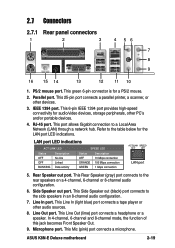
... port. This Line Out (lime) port connects a headphone or a speaker. In 4-channel, 6-channel and 8-channel mode, the function of this jack becomes Front Speaker Out. 9. ASUS K8N-E Deluxe motherboard 2-19 Parallel port. Line In port. Microphone port. Refer to the side speakers in an 8-channel audio configuration. 7. This Side Speaker out (black) port connects...
... port. This Line Out (lime) port connects a headphone or a speaker. In 4-channel, 6-channel and 8-channel mode, the function of this jack becomes Front Speaker Out. 9. ASUS K8N-E Deluxe motherboard 2-19 Parallel port. Line In port. Microphone port. Refer to the side speakers in an 8-channel audio configuration. 7. This Side Speaker out (black) port connects...

K8N-E Deluxe User's Manual
Page 43
... (usually zigzag) on the UltraDMA cable connector. IDE connectors (40-1 pin PRI_IDE, SEC_IDE) This connector supports the provided UltraDMA IDE hard disk ribbon cable. PIN 1 ASUS K8N-E Deluxe motherboard 2-21 Connect the cable's blue connector to the primary (recommended) or secondary IDE connector, then connect the gray connector to the UltraDMA slave device (hard...
... (usually zigzag) on the UltraDMA cable connector. IDE connectors (40-1 pin PRI_IDE, SEC_IDE) This connector supports the provided UltraDMA IDE hard disk ribbon cable. PIN 1 ASUS K8N-E Deluxe motherboard 2-21 Connect the cable's blue connector to the primary (recommended) or secondary IDE connector, then connect the gray connector to the UltraDMA slave device (hard...

K8N-E Deluxe User's Manual
Page 45
...ATA connectors support SATA hard disks that you can configure as a RAID set using the SATALink™ SATA RAID Management Software only. ASUS K8N-E Deluxe motherboard 2-23 See Chapter 5 for details on RAID configuration. See section "5.5.3 Silicon Image RAID configurations" for details. • Refer to...RSATA_RXN1 GND ® K8V-E SATA_RAID2 SATA_RAID4 GND RSATA_TXP2 RSATA_TXN2 GND RSATA_RXP2 RSATA_RXN2 GND GND RSATA_TXP2 RSATA_TXN2 GND RSATA_RXP2 RSATA_RXN2 GND K8N-E SATA RAID Connectors • To create a RAID set, make sure that you have installed the Serial ATA devices ...
...ATA connectors support SATA hard disks that you can configure as a RAID set using the SATALink™ SATA RAID Management Software only. ASUS K8N-E Deluxe motherboard 2-23 See Chapter 5 for details on RAID configuration. See section "5.5.3 Silicon Image RAID configurations" for details. • Refer to...RSATA_RXN1 GND ® K8V-E SATA_RAID2 SATA_RAID4 GND RSATA_TXP2 RSATA_TXN2 GND RSATA_RXP2 RSATA_RXN2 GND GND RSATA_TXP2 RSATA_TXN2 GND RSATA_RXP2 RSATA_RXN2 GND K8N-E SATA RAID Connectors • To create a RAID set, make sure that you have installed the Serial ATA devices ...

K8N-E Deluxe User's Manual
Page 47
... CPU. • Do not forget to fit these connectors in only one orientation. In addition to the 20-pin ATX power connector, this motherboard requires that your ATX 12V power supply can provide 8A on the +12V lead and at least 1A on the +5-volt standby lead (+5VSB)....The plugs from the power supply are for a fully configured system. 7. ATX12V GND +12V DC GND +12V DC ® K8V-E K8N-E ATX Power Connectors ATXPWR Pin 1 +12.0VDC +5VSB PWR_OK COM +5.0VDC COM +5.0VDC COM +3.3VDC +3.3VDC +5.0VDC +5.0VDC -5.0VDC COM COM COM PS_ON# COM -12.0VDC +3.3VDC ASUS K8N-E Deluxe motherboard 2-25
... CPU. • Do not forget to fit these connectors in only one orientation. In addition to the 20-pin ATX power connector, this motherboard requires that your ATX 12V power supply can provide 8A on the +12V lead and at least 1A on the +5-volt standby lead (+5VSB)....The plugs from the power supply are for a fully configured system. 7. ATX12V GND +12V DC GND +12V DC ® K8V-E K8N-E ATX Power Connectors ATXPWR Pin 1 +12.0VDC +5VSB PWR_OK COM +5.0VDC COM +5.0VDC COM +3.3VDC +3.3VDC +5.0VDC +5.0VDC -5.0VDC COM COM COM PS_ON# COM -12.0VDC +3.3VDC ASUS K8N-E Deluxe motherboard 2-25

K8N-E Deluxe User's Manual
Page 49
Doing so will damage the motherboard! Internal audio connectors (4-pin CD, AUX) These connectors allow you to the IEEE 1394 (red) connector. TPA0GND TPB0+12V GND ® K8V-E K8N-E IEEE-1394 Connector IE1394_2 1 TPA0+ GND TPB0+ +12V NEVER connect a USB cable to receive ... Audio Channel Ground Left Audio Channel K8N-E Internal Audio Connectors 10. You can also connect a 1394-compliant internal hard disk to this connector. IEEE 1394 connectors (10-1 pin IE1394_2) This connector is for the bundled IEEE 1394 module. ASUS K8N-E Deluxe motherboard 2-27 9. Attach the 10-1 ...
Doing so will damage the motherboard! Internal audio connectors (4-pin CD, AUX) These connectors allow you to the IEEE 1394 (red) connector. TPA0GND TPB0+12V GND ® K8V-E K8N-E IEEE-1394 Connector IE1394_2 1 TPA0+ GND TPB0+ +12V NEVER connect a USB cable to receive ... Audio Channel Ground Left Audio Channel K8N-E Internal Audio Connectors 10. You can also connect a 1394-compliant internal hard disk to this connector. IEEE 1394 connectors (10-1 pin IE1394_2) This connector is for the bundled IEEE 1394 module. ASUS K8N-E Deluxe motherboard 2-27 9. Attach the 10-1 ...

K8N-E Deluxe User's Manual
Page 51
...connector colors as a chassis intrusion sensor or microswitch. Chassis intrusion connector (4-1 pin CHASSIS) This lead is color-coded for a chassis designed with a jumper cap. ASUS K8N-E Deluxe motherboard 2-29 Speaker Power LED Connector PLED+ PLED+5V Ground Ground Speaker IDE_LED+ IDE_LED- 13. By default, the pins labeled "Chassis Signal" and "Ground" are ...-E IDE_LED Switch* * Requires an ATX power supply. This requires an external detection mechanism such as described. CHASSIS +5VSB_MB Chassis Signal GND ® K8V-E K8N-E Chassis Alarm Lead (Default) 14.
...connector colors as a chassis intrusion sensor or microswitch. Chassis intrusion connector (4-1 pin CHASSIS) This lead is color-coded for a chassis designed with a jumper cap. ASUS K8N-E Deluxe motherboard 2-29 Speaker Power LED Connector PLED+ PLED+5V Ground Ground Speaker IDE_LED+ IDE_LED- 13. By default, the pins labeled "Chassis Signal" and "Ground" are ...-E IDE_LED Switch* * Requires an ATX power supply. This requires an external detection mechanism such as described. CHASSIS +5VSB_MB Chassis Signal GND ® K8V-E K8N-E Chassis Alarm Lead (Default) 14.

K8N-E Deluxe User's Manual
Page 54
Chapter summary 3.1 Starting up for the first time 3-1 3.2 Powering off the computer 3-2 3.3 ASUS POST Reporter 3-3 ASUS K8N-E Deluxe motherboard
Chapter summary 3.1 Starting up for the first time 3-1 3.2 Powering off the computer 3-2 3.3 ASUS POST Reporter 3-3 ASUS K8N-E Deluxe motherboard


