User Guide
Page 6
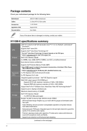
... panel jack-retasking. (continued on the CPU types. ** Refer to guard the quality of individual CPUs. H110M-K specifications summary CPU Chipset Memory Expansion slots Graphics Storage Audio LGA1151 socket for Intel® 6th Generation Core™...H110 Express Chipset: - 4 x SATA 6.0 Gb/s ports (gray) Realtek® ALC887 8-channel High Definition Audio CODEC - Intel® HD Graphics support Multi-VGA output support: DVI-D/RGB port - Package contents Check your motherboard package for the following items. Motherboard Cables Accessories Application DVD Documentation ASUS H110M...
... panel jack-retasking. (continued on the CPU types. ** Refer to guard the quality of individual CPUs. H110M-K specifications summary CPU Chipset Memory Expansion slots Graphics Storage Audio LGA1151 socket for Intel® 6th Generation Core™...H110 Express Chipset: - 4 x SATA 6.0 Gb/s ports (gray) Realtek® ALC887 8-channel High Definition Audio CODEC - Intel® HD Graphics support Multi-VGA output support: DVI-D/RGB port - Package contents Check your motherboard package for the following items. Motherboard Cables Accessories Application DVD Documentation ASUS H110M...
User Guide
Page 7
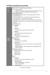
... real time UEFI BIOS EZ Mode - Audio that roars on the next page) vii ASUS Ai Charger - Featuring friendly graphics user interface - H110M-K specifications summary LAN USB ASUS special features Realtek® RTL8111H Gigabit LAN supports LANGuard Intel® H110 Express Chipset: - 4 x USB 3.0/2.0 ports (2 ports at mid-board; 2 ports at back panel, blue, Type...
... real time UEFI BIOS EZ Mode - Audio that roars on the next page) vii ASUS Ai Charger - Featuring friendly graphics user interface - H110M-K specifications summary LAN USB ASUS special features Realtek® RTL8111H Gigabit LAN supports LANGuard Intel® H110 Express Chipset: - 4 x USB 3.0/2.0 ports (2 ports at mid-board; 2 ports at back panel, blue, Type...
User Guide
Page 9
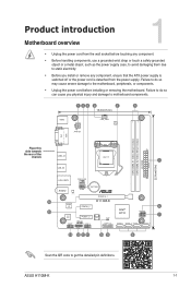
Failure to do so may cause severe damage to get the detailed pin definitions. ASUS H110M-K 1-1 Product introduction Motherboard overview 1 • Unplug the power cord from the power supply. Failure to do so can cause you install ...Place this side towards the rear of the chassis USB3_34 LGA1151 1 USB_56 LAN_USB78 CHA_FAN AUDIO RTL 8111H COM BATTERY PCIEX16_1 16 H110M-K Super I/O PCIEX1_1 6 15 Intel® SPEAKER H110 7 ALC 887 PCIEX1_2 128Mb BIOS CLRTC F_PANEL AAFP SPDIF_OUT USB910 USB3_12 SATA6G_1 SATA6G_2 SATA6G_3 SATA6G_4 TPM 14 13 12 11 10 ...
Failure to do so may cause severe damage to get the detailed pin definitions. ASUS H110M-K 1-1 Product introduction Motherboard overview 1 • Unplug the power cord from the power supply. Failure to do so can cause you install ...Place this side towards the rear of the chassis USB3_34 LGA1151 1 USB_56 LAN_USB78 CHA_FAN AUDIO RTL 8111H COM BATTERY PCIEX16_1 16 H110M-K Super I/O PCIEX1_1 6 15 Intel® SPEAKER H110 7 ALC 887 PCIEX1_2 128Mb BIOS CLRTC F_PANEL AAFP SPDIF_OUT USB910 USB3_12 SATA6G_1 SATA6G_2 SATA6G_3 SATA6G_4 TPM 14 13 12 11 10 ...
User Guide
Page 11
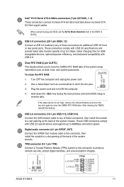
...platform integrity. +5V SPDIFOUT GND PIN 1 SPDIF_OUT TPM +3VSB S_PCIRST#_TBD GND C_PCICLK_TPM +3V +3V F_CLKRUN F_SERIRQ F_FRAME# F_LAD3 F_LAD2 F_LAD1 F_LAD0 PIN 1 ASUS H110M-K 1-3 These connectors comply with USB 2.0 specifications and supports up to short the two pins. Use a metal object such as date, time, and system... module cable to this connector to re-enter data. Turn OFF the computer and unplug the power cord. 2. Intel® H110 Serial ATA 6.0Gb/s connectors (7-pin SATA6G_1~4) These connectors connect to a slot opening at the back of the system chassis.
...platform integrity. +5V SPDIFOUT GND PIN 1 SPDIF_OUT TPM +3VSB S_PCIRST#_TBD GND C_PCICLK_TPM +3V +3V F_CLKRUN F_SERIRQ F_FRAME# F_LAD3 F_LAD2 F_LAD1 F_LAD0 PIN 1 ASUS H110M-K 1-3 These connectors comply with USB 2.0 specifications and supports up to short the two pins. Use a metal object such as date, time, and system... module cable to this connector to re-enter data. Turn OFF the computer and unplug the power cord. 2. Intel® H110 Serial ATA 6.0Gb/s connectors (7-pin SATA6G_1~4) These connectors connect to a slot opening at the back of the system chassis.