User Manual
Page 7
... (electrical and electronic equipment) should not be placed in municipal waste. How this guide Audience This guide provides general information and installation instructions about the ASUS G1-P5G43 barebone system. Entsorgung gebrauchter Batterien nach Angaben des Herstellers. DO NOT throw the mercury-containing button cell battery in municipal waste. Chapter 1: System introduction ... type recommended by the manufacturer. Ersatz nur durch denselben oder einem vom Hersteller empfohlenem ähnljchen Typ. Replace only with hardware knowledge of the ASUS G1-P5G43.
... (electrical and electronic equipment) should not be placed in municipal waste. How this guide Audience This guide provides general information and installation instructions about the ASUS G1-P5G43 barebone system. Entsorgung gebrauchter Batterien nach Angaben des Herstellers. DO NOT throw the mercury-containing button cell battery in municipal waste. Chapter 1: System introduction ... type recommended by the manufacturer. Ersatz nur durch denselben oder einem vom Hersteller empfohlenem ähnljchen Typ. Replace only with hardware knowledge of the ASUS G1-P5G43.
User Manual
Page 9
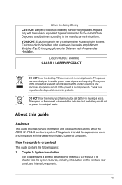
Support DVD 4. Installation guide ix Cable • AC power cable 3. Item description 1. ASUS G1-P5G43 barebone system with • ASUS motherboard • Power supply unit • ASUS chassis 2. System package contents Check your G1-P5G43 system package for the following items. If any of the items is damaged or missing, contact your retailer immediately.
Support DVD 4. Installation guide ix Cable • AC power cable 3. Item description 1. ASUS G1-P5G43 barebone system with • ASUS motherboard • Power supply unit • ASUS chassis 2. System package contents Check your G1-P5G43 system package for the following items. If any of the items is damaged or missing, contact your retailer immediately.
User Manual
Page 11
System introduction Chapter 1 This chapter gives a general description of the ASUS G1-P5G43. The chapter lists the system features including introduction on the front and rear panel, and internal components.
System introduction Chapter 1 This chapter gives a general description of the ASUS G1-P5G43. The chapter lists the system features including introduction on the front and rear panel, and internal components.
User Manual
Page 12
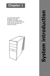
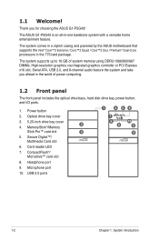
Power button 1 4 56 2. 1.1 Welcome! The ASUS G1-P5G43 is an all-in the 775-land package. The system comes in a stylish casing and powered by the ASUS motherboard that supports the Intel® Core™2 Extreme / Core™2 Quad / Core™2 Duo / Pentium® Dual-Core processors in -one barebone system with a ... graphics via integrated graphics controller or PCI Express x16 slot, Serial ATA, USB 2.0, and 8-channel audio feature the system and take you for choosing the ASUS G1-P5G43! USB 2.0 ports 1-2 Chapter 1: System introduction Card reader LED 7.
Power button 1 4 56 2. 1.1 Welcome! The ASUS G1-P5G43 is an all-in the 775-land package. The system comes in a stylish casing and powered by the ASUS motherboard that supports the Intel® Core™2 Extreme / Core™2 Quad / Core™2 Duo / Pentium® Dual-Core processors in -one barebone system with a ... graphics via integrated graphics controller or PCI Express x16 slot, Serial ATA, USB 2.0, and 8-channel audio feature the system and take you for choosing the ASUS G1-P5G43! USB 2.0 ports 1-2 Chapter 1: System introduction Card reader LED 7.
User Manual
Page 13
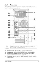
... the rear vent , and the ambience temperature is for the power cable and plug. 2. Power supply unit (PSU) fan vent. Chassis fan vent. Power connector. ASUS G1-P5G43 1-3 This connector is for the fan that provides ventilation inside the power supply unit. 4. This switch is limited up to 35oC to prevent the system...
... the rear vent , and the ambience temperature is for the power cable and plug. 2. Power supply unit (PSU) fan vent. Chassis fan vent. Power connector. ASUS G1-P5G43 1-3 This connector is for the fan that provides ventilation inside the power supply unit. 4. This switch is limited up to 35oC to prevent the system...
User Manual
Page 15
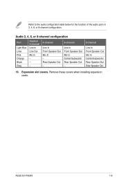
Remove these covers when installing expansion cards. Refer to the audio configuration table below for the function of the audio ports in 2, 4, 6, or 8-channel configuration. ASUS G1-P5G43 1-5 Expansion slot covers. Audio 2, 4, 6, or 8-channel configuration Port Light Blue Lime Pink Orange Black Gray Headset. 2-channel Line In Line Out Mic In - - - 4-channel Line ...
Remove these covers when installing expansion cards. Refer to the audio configuration table below for the function of the audio ports in 2, 4, 6, or 8-channel configuration. ASUS G1-P5G43 1-5 Expansion slot covers. Audio 2, 4, 6, or 8-channel configuration Port Light Blue Lime Pink Orange Black Gray Headset. 2-channel Line In Line Out Mic In - - - 4-channel Line ...
User Manual
Page 19
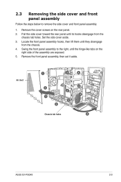
... tab holes. Locate the front panel assembly hooks, then lift them until the hinge-like tabs on the rear panel. 2. Air duct 1 3 4 2 3 1 3 2 Chassis tab holes 4 4 4 ASUS G1-P5G43 2-3
... tab holes. Locate the front panel assembly hooks, then lift them until the hinge-like tabs on the rear panel. 2. Air duct 1 3 4 2 3 1 3 2 Chassis tab holes 4 4 4 ASUS G1-P5G43 2-3
User Manual
Page 21
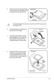
... remove the PnP cap unless you are installing a CPU. 3. Retention tab A B Load lever To prevent damage to a 135º angle. 4. CPU notch Gold triangle mark ASUS G1-P5G43 Alignment key 2-5 Lift the load lever in the direction of the socket then fit the socket alignment key into the CPU notch. Position the CPU...
... remove the PnP cap unless you are installing a CPU. 3. Retention tab A B Load lever To prevent damage to a 135º angle. 4. CPU notch Gold triangle mark ASUS G1-P5G43 Alignment key 2-5 Lift the load lever in the direction of the socket then fit the socket alignment key into the CPU notch. Position the CPU...
User Manual
Page 23
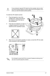
... or CPU before you install the heatsink and fan assembly. When the fan and heatsink assembly is properly applied to the connector on the motherboard. ASUS G1-P5G43 2-7 Do not forget to plug this connector. Hardware monitoring errors can occur if you fail to connect the CPU fan connector! To install the CPU...
... or CPU before you install the heatsink and fan assembly. When the fan and heatsink assembly is properly applied to the connector on the motherboard. ASUS G1-P5G43 2-7 Do not forget to plug this connector. Hardware monitoring errors can occur if you fail to connect the CPU fan connector! To install the CPU...
User Manual
Page 25
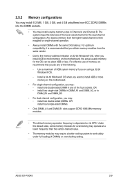
... install 4GB or more memory on its SPD. OR - Under the default state, some memory modules for the OS can be about 3GB or less. ASUS G1-P5G43 2-9 For effective use of memory, we recommend that you obtain memory modules from the higher-sized channel is recommended that you do any of 3GB...
... install 4GB or more memory on its SPD. OR - Under the default state, some memory modules for the OS can be about 3GB or less. ASUS G1-P5G43 2-9 For effective use of memory, we recommend that you obtain memory modules from the higher-sized channel is recommended that you do any of 3GB...
User Manual
Page 29
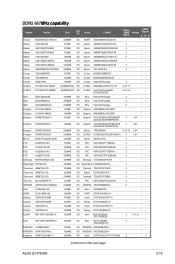
...; KINGBOX DDRII1G667MHz 1024MB DS KINGBOX EPD264082200-4 • •• Leadmax LRMP512U64A8-Y5 1024MB DS Hynix HY5PS12821CFP-Y5C702AA 5 • •• (continued on the next page) ASUS G1-P5G43 2-13 Size SS/ DS Brand ChipNO. DDR2 667�M�H��z�c�a�p��a�b�i�li�ty� Vendor...
...; KINGBOX DDRII1G667MHz 1024MB DS KINGBOX EPD264082200-4 • •• Leadmax LRMP512U64A8-Y5 1024MB DS Hynix HY5PS12821CFP-Y5C702AA 5 • •• (continued on the next page) ASUS G1-P5G43 2-13 Size SS/ DS Brand ChipNO. DDR2 667�M�H��z�c�a�p��a�b�i�li�ty� Vendor...
User Manual
Page 31
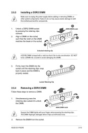
DO NOT force a DIMM into the 3 socket until the retaining clips snap back in only one direction. ASUS G1-P5G43 2-15 Unlock a DDR2 DIMM socket by pressing the retaining clips outward. 2. Simultaneously press the 1 retaining clips outward to remove a DIMM. 2 1. Align a DIMM on the socket ...
DO NOT force a DIMM into the 3 socket until the retaining clips snap back in only one direction. ASUS G1-P5G43 2-15 Unlock a DDR2 DIMM socket by pressing the retaining clips outward. 2. Simultaneously press the 1 retaining clips outward to remove a DIMM. 2 1. Align a DIMM on the socket ...
User Manual
Page 33
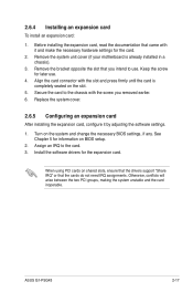
Before installing the expansion card, read the documentation that came with the slot and press firmly until the card is already installed in a chassis). 3. ASUS G1-P5G43 2-17 See Chapter 5 for later use . Install the software drivers for the card. 2. Remove the system unit cover (if your motherboard is completely seated on ...
Before installing the expansion card, read the documentation that came with the slot and press firmly until the card is already installed in a chassis). 3. ASUS G1-P5G43 2-17 See Chapter 5 for later use . Install the software drivers for the card. 2. Remove the system unit cover (if your motherboard is completely seated on ...
User Manual
Page 35
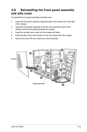
... To reinstall the front panel assembly and side cover: 1. Insert the six side cover hooks into the chassis tab holes . 4. Air duct 5 2 4 2 5 2 3 Chassis tab holes 1 1 1 2 ASUS G1-P5G43 2-19
... To reinstall the front panel assembly and side cover: 1. Insert the six side cover hooks into the chassis tab holes . 4. Air duct 5 2 4 2 5 2 3 Chassis tab holes 1 1 1 2 ASUS G1-P5G43 2-19
User Manual
Page 39
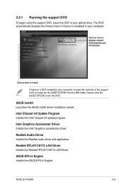
Double-click the ASSETUP.EXE to run the DVD. ASUS InstAll Launches the ASUS InstAll driver installation wizard. Realtek RTL8111/8112 LAN Driver Installs the Realtek® RTL8111/8112 LAN Driver. Click an icon to display support DVD/motherboard ... of the support DVD to locate the file ASSETUP.EXE from the BIN folder. Intel Graphics Accelerator Driver Installs the Intel® Graphics accerlerator driver. ASUS EPU-4 Engine Installs the ASUS EPU-4 Engine. ASUS G1-P5G43 3-3
Double-click the ASSETUP.EXE to run the DVD. ASUS InstAll Launches the ASUS InstAll driver installation wizard. Realtek RTL8111/8112 LAN Driver Installs the Realtek® RTL8111/8112 LAN Driver. Click an icon to display support DVD/motherboard ... of the support DVD to locate the file ASSETUP.EXE from the BIN folder. Intel Graphics Accelerator Driver Installs the Intel® Graphics accerlerator driver. ASUS EPU-4 Engine Installs the ASUS EPU-4 Engine. ASUS G1-P5G43 3-3
User Manual
Page 41
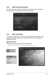
Motherboard Info Displays the general specifications of the support DVD. 3.3.3 ASUS Contact information Click the Contact tab to display the specified information. ASUSTeK Computer INC. Click an icon to display the ASUS contact information. G1-P5G43 Rev X.0x American Megatrends Inc. 0205 08/13/2009 1024 KBytes ASUS G1-P5G43 3-5 You can also find this information on the inside front cover of this user guide. 3.3.4 Other information The icons on the top right corner of the screen give additional information on the motherboard and the contents of the motherboard.
Motherboard Info Displays the general specifications of the support DVD. 3.3.3 ASUS Contact information Click the Contact tab to display the specified information. ASUSTeK Computer INC. Click an icon to display the ASUS contact information. G1-P5G43 Rev X.0x American Megatrends Inc. 0205 08/13/2009 1024 KBytes ASUS G1-P5G43 3-5 You can also find this information on the inside front cover of this user guide. 3.3.4 Other information The icons on the top right corner of the screen give additional information on the motherboard and the contents of the motherboard.
User Manual
Page 45
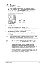
You must turn ON the computer. 4. ASUS G1-P5G43 4-3 4.3 Jumpers 1. Move the jumper cap from pins 1-2 (default) to overclocking, use the C.P.R. Keep the cap on CLRTC jumper default position. Except when clearing the RTC ...
You must turn ON the computer. 4. ASUS G1-P5G43 4-3 4.3 Jumpers 1. Move the jumper cap from pins 1-2 (default) to overclocking, use the C.P.R. Keep the cap on CLRTC jumper default position. Except when clearing the RTC ...
User Manual
Page 47
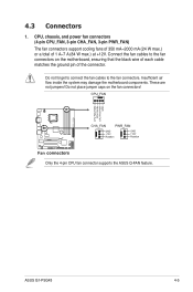
... cooling fans of 350 mA~2000 mA (24 W max.) or a total of the connector. Insufficient air flow inside the system may damage the motherboard components. ASUS G1-P5G43 4-5 4.3 Connectors 1. Only the 4-pin CPU fan connector supports the...
... cooling fans of 350 mA~2000 mA (24 W max.) or a total of the connector. Insufficient air flow inside the system may damage the motherboard components. ASUS G1-P5G43 4-5 4.3 Connectors 1. Only the 4-pin CPU fan connector supports the...
User Manual
Page 49
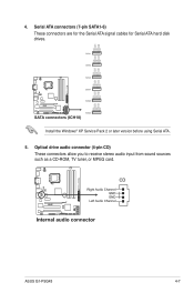
Install the Windows® XP Service Pack 2 or later version before using Serial ATA. 5. Optical drive audio connector (4-pin CD) These connectors allow you to receive stereo audio input from sound sources such as a CD-ROM, TV tuner, or MPEG card. 4. Serial ATA connectors (7-pin SATA1-6) These connectors are for the Serial ATA signal cables for Serial ATA hard disk drives. ASUS G1-P5G43 4-7
Install the Windows® XP Service Pack 2 or later version before using Serial ATA. 5. Optical drive audio connector (4-pin CD) These connectors allow you to receive stereo audio input from sound sources such as a CD-ROM, TV tuner, or MPEG card. 4. Serial ATA connectors (7-pin SATA1-6) These connectors are for the Serial ATA signal cables for Serial ATA hard disk drives. ASUS G1-P5G43 4-7

User Manual
Page 51
... blinks when the system is in sleep mode. • Hard disk drive activity LED (2-pin IDE_LED) This 2-pin connector is for the HDD Activity LED. 7. ASUS G1-P5G43 4-9
... blinks when the system is in sleep mode. • Hard disk drive activity LED (2-pin IDE_LED) This 2-pin connector is for the HDD Activity LED. 7. ASUS G1-P5G43 4-9


